HONDA CIVIC 1998 6.G Workshop Manual
Manufacturer: HONDA, Model Year: 1998, Model line: CIVIC, Model: HONDA CIVIC 1998 6.GPages: 2189, PDF Size: 69.39 MB
Page 411 of 2189
PGM-FI System
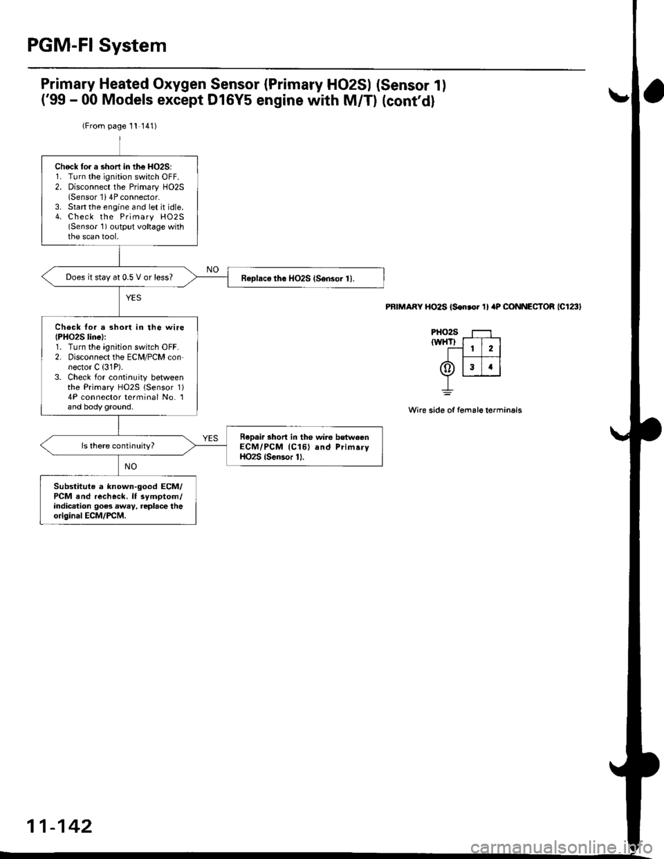
Primary Heated Oxygen Sensor (Primary HO2SI (Sensor 1)
('99 - 00 Models except Dl6Y5 engine with M/T) (cont'd)
PRIMARY HO2S {S€oror 1} 4P CONNECTOR lc123l
PHO2S f----l,wHl_l:-f;-l
0ffi
_L
Wire side of female terminals
(From page 11 141)
Chock fo. a shori in the HO2S:1. Turn the ignition switch OFF.2. Disconnect the Primary HO2S(Sensor 1i 4P connector.3. Stan the engine and let it idle.4. Check the Primary HO2S(Sensor 1) output voltage withthe scan tool.
Does it stay at 0.5 V or less?Roplaco the HO2S (Sensor 1).
Check tor a short in the wire{PHO2S linel:1. Turn the ignition switch OFF.2. Disconnect the EcltI/PcM con-nector C {31P).3. Check for continuity betweenthe Primary HO2S lsensor 1)4P connector terminal No. 1and body ground.
ReDair shorl in the wi.e betweenECM/PCM (Cl61 and PrimaryHO2S (Sercor 11.
Substitute a known-good ECM/PCM and recheck. lf symptom/indication goes away, replace theoriginal ECM/PCM.
11-142
Page 412 of 2189
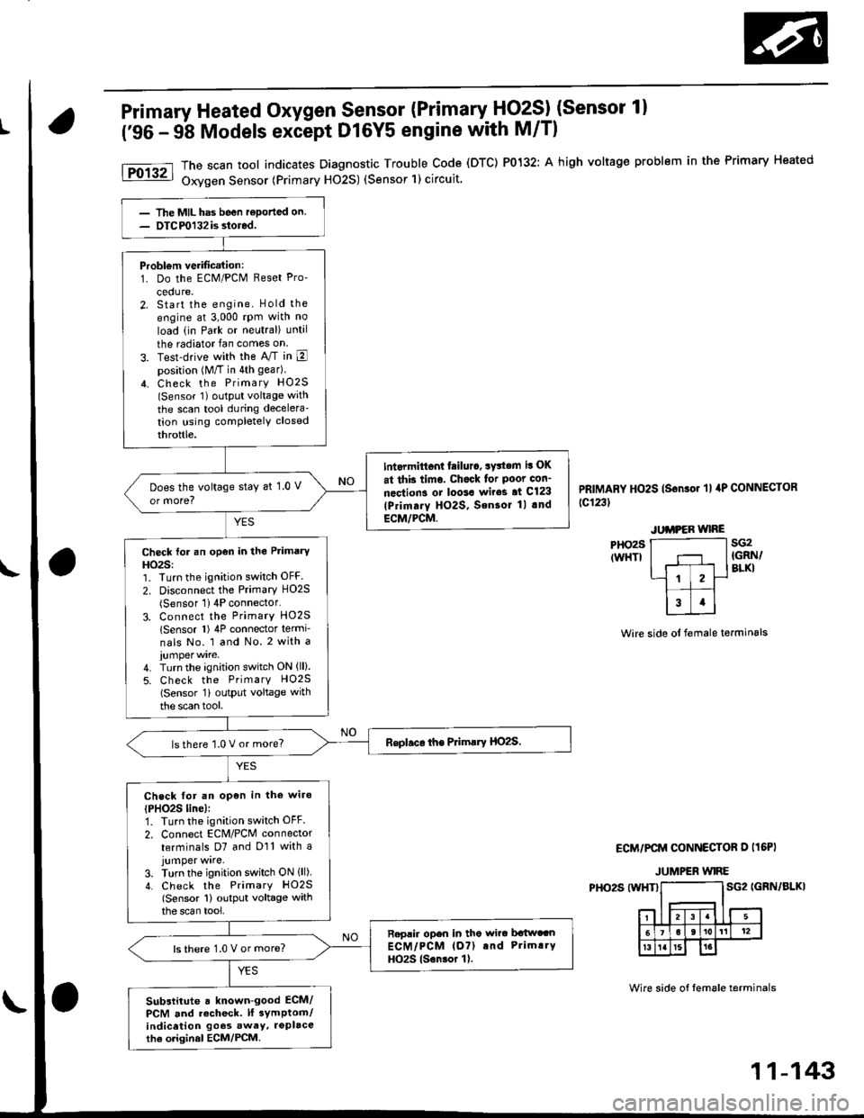
Primary Heated Oxygen Sensor (Primary HO2SI (Sensor 1)
('96 - 9b Models except Dl6Y5 engine with M/Tl
PHO29IWHT}
The scan tool indicates Diagnostic Trouble Code (DTC) P0132: A high voltage problem in the Primary Heated
Oxygen Sensor (Primary H02S) (Sensor'l) circuit.
PRIMARY HO2S (Sonso. 'll 4P CONNECToR
tc123t
sG2IGRN/BLKI
Wire side ot female terminals
ECM/PCM CONNECTOR D I16PI
JUMPER WIRE
PHO2S (WHT}SG2 IGRN/BLKI
Wire side of tem6le terminals
Probl€m verification:1. Do the ECM/PCM Reset Pro-
cedure.2. Start the engine. Hold the
engine at 3,000 rpm with no
load (in Park or neutral) until
the radiator fan comes on
3. Test-drive with the A/T in Eposition (M/T in 4th gear)
4. Check the PrimarY HO2S(Sensor 1) oLltPut voltage with
the scan tool during decelera'tion using completely closed
throttle.
Int.rmittont fiilur., system it OK
at thb timo. Chock for Poot con-
nections or loo3a wir63 at Cl23
lPrimarY HO2S, SensoJ 1l .nd
ECM/PCM.
Does the voltage stay at 1.0 V
or more?
Check for an open in the Primary
HO2S:1. Turn the ignition switch OFF.
2. Disconnect the Primary HO2S(Sensor 1) 4P connector'
3. Connect the PrimarY HO25
lSensor l) 4P connector termi-
nals No. 1 and No. 2 with a
4. Turn the ignition switch ON (ll).
5. Check the PrimarY H02S(Sensor 1i outPut voltage with
the scan tool.
lsthere 1.0 V or more?
Check for an open in the wiro
{PHO2S line):1. Turn the ignition switch OFF.
2. Connect EcM/PcM connector
terminals D7 and D11 with ajumper wrre,3. Turn the ignition switch ON lll)4. Check the PrimarY HO2S(Sensor 1) output voltage withthe scan tool,
Replir open in tho wirc b€twccnECM/PCM lo?) and Prim!.Y
HO2S lsonsor 1).ls there 1.0 V or more?
Substitute a known-good ECM/PCM and recheck. lf 3ymptom/indicetion goos awey, roplacethe oliginal ECM/PCM.
11-143
Page 413 of 2189
PGM-FI System
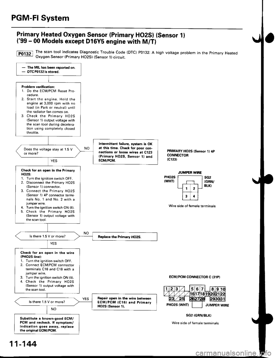
Primary Heated Oxygen Sensor (Primary HO2SI (Sensor 1)
('99 - 00 Models except D16Y5 engine with M/T)
The scan tool indicates Diagnostic Trouble Code (DTC) P0132: A high voltage problem in the primary HeatedOxygen Sensor (Primary HO2S) {Sensor I ) circuit.
PRIMARY HO2S ls€n3or 1' 4PCONNECTOR(c123t
PHO2SIWHTI
Wire side of temale terminals
ECM/PCM CONNECTOR C 131PI
sG2(GRN/
BLK)
SG2 IGRN/8LK}
Ware side of female terminals
The MIL has been reported on.OTCP0132 is stored.
Problem vorificalion:1. Do the ECM/PCM Reset Procedure,Start the engine. Hold theengane at 3,000 rpm with noload (in Park or neutral) untilthe radiator fan comes on.Check the Primary HO25{Sensor lioutput voltage withthe scan tool during decelera-taon using completely closedthrottle.
Intermittent tailure, systom k OKat this time. Chock tor poor con-nections or looso wir* at Cl23(Primaly HO2S, Sonsor 1) andECM/PCM.
Check lor an open in the PrimaryH02S:1. Turn the ignition switch OFF.2. Disconnect the Primary HO2SlSensor 1)connector.3. Connect the Primary H02S(Sensor 1)4P connector terminals No. 1 and No. 2 with a
4. Turn the ignition switch ON (ll).5. Check the Primary H02S{Sensor l) output voltage withthe scan tool.
ls there 1.5 V or more?
Check lor an open in th€ wire(PHO25 lin€l:1. Turn the ignition switch OFF.2. Connect ECM/PCM connectorterminals C16 and C18 with ajumper wire.3. Turn the ignition switch ON {lli.4. Check the Primary HO2S(Sensor 1i output voltage withthe scan tool,
Roptir op.n in tho wire betweonECM/PCM lCl6l and Prim.ryHO2S lsensor 11.
ls there 1.5 V or more?
Subsiitute a known-good ECM/PCM and r.check. lf symptom/indication goos away, replecethe original ECM/PCM.
11-144
Page 414 of 2189
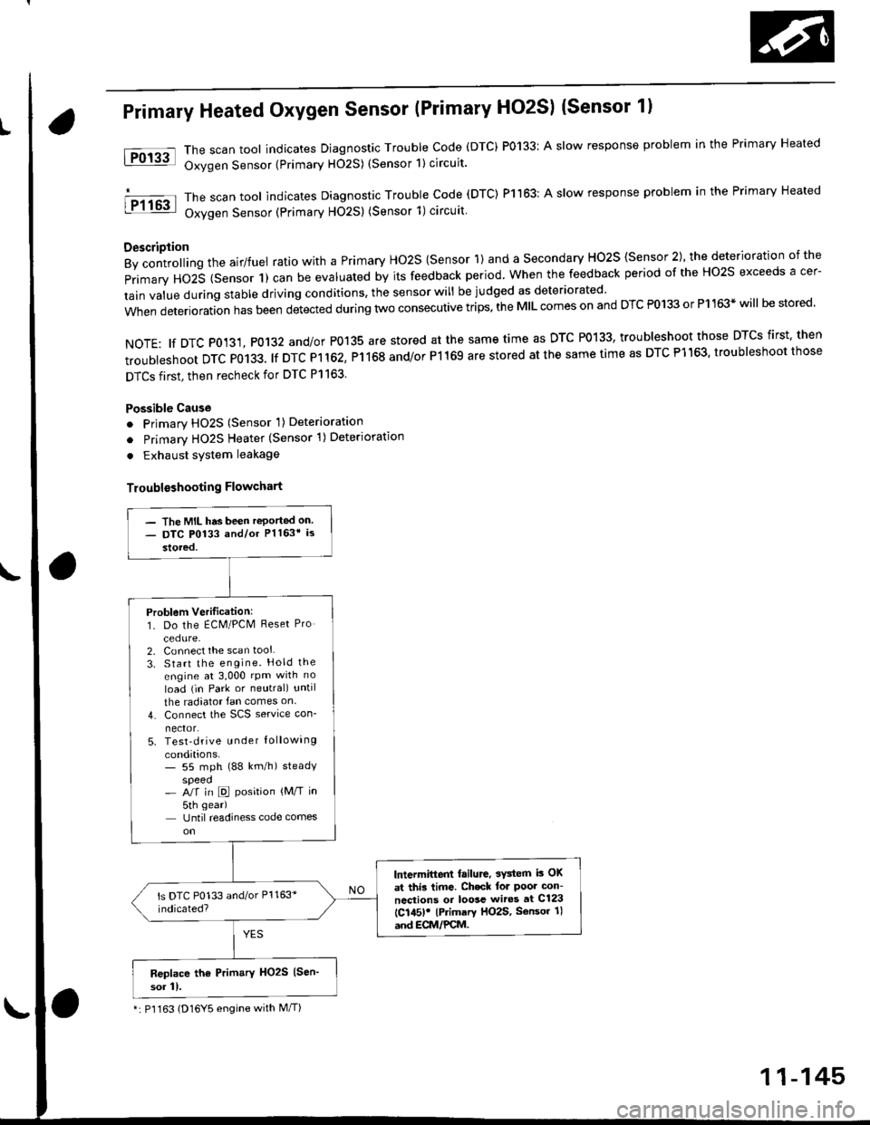
Primary Heated Oxygen Sensor (Primary HO2S) (Sensor 1l
The scan tool indicates Diagnostic Trouble Code (DTC) P0133: A slow response problem in the Primary Heated
Oxygen Sensor {Primary H02S) (Sensor 1) circuit.
The scan tool indicates Diagnostic Trouble code (DTC) Pl163: A slow response problem in the Primary Heated
Oxygen Sensor (Primary HO2S) (Sensor 1)circuit
Description
By controlling the airlfuel ratio with a Primary Ho2S {Sensor 1) and a secondary HO2S {Sensor 2), the deterioration of the
primary HO2S (Sensor 1) can be evaluated by its feedback period. when the feedback period of the Ho2s exceeds a cer-
tain value during stable driving conditions, the sensor will be judged as deteriorated
when deterioration has been detected during two consecutive trips. the MIL comes on and DTC P0133 or P1163* will be stored'
NOTE: tf DTC P0131, P0132 and/or P0135 are stored at the same time as DTC P0133, troubleshoot those DTCS first' then
troubleshoot DTC P0133. lf DTC Pl 162, P1168 and/or P1169 are stored at the same time as DTC P1163, troubleshoot those
DTCS first, then recheck for DTC Pl163.
Possible Cause
o Primary HO2S (Sensor 'l) Deterioration
o Primary HO2S Heater (Sensor 1)Deterioration
. Exhaust system leakage
Troublsshooting Flowchart
tFol3al
I P1163
- The MIL has been reported on- DTC P0133 and/or Pl163* is
stored,
Problem Verilication:1. Do the ECM/PCM Reset Pro
cedure-2. Connect the scan tool
3. Start the engine. Hold the
engine at 3,000 rpm with no
load (in Park or neutral) until
the radiator fan comes on
4. Connect the SCS service con-
nector.5. Test-drive u nder Iollowing
conditions.- 55 mph (88 km/h) steadyspeed- A/f in D position {M/T in
5th gear)
Until readiness code comes
lntermittent failure, 3Y3tem i3 OK
at thi3 time. Ch.ck lol Poor con-
ncctions or loosc wiros at C123
{C145)! lPrimary HO2S, Sensor 1l
and ECM/PCM.
Replace th6 Prim.ry HO2S (Sen'
sor 11.
*: P'l163 (D16Y5 engine with M/T)
11-145
Page 415 of 2189
PGM-FI System
Itil-"w Heated Oxygen Sensor (primary HO2S) (sensor 1l(Dl6Y5 engine with M/Tl
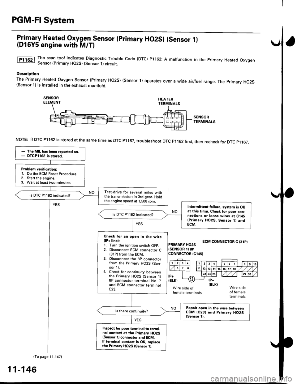
The scan tool indicates Diagnostic Trouble Code (DTC) p1162: A malfunction in the primary Heated OxygenSensor (Primary HO2S) (Sensor 1) circutt.
Doscription
The Primary Heated orygen sensor (Primary Ho2s) {sensor 1) operates over a wide airlfuel range. The primary Ho2S(Sensor 1) is installed in the exhaust manifold.
SEI{SORELEMENT
SENSORTERMINALS
ECM CONNECTOR C (31PIPRIMARY HO2S(SENSOR 1)8PCONNECTOR {Clir5)
female terminalsof femaleterminals
NOTE: lf DTC Pl162 is stored at the same time as DTC Pl167, troubteshoot DTC p1162 first, then recheck for DTC p1167.
(To page 11-147)
- lh6 MIL hes b6on reDorted on.- DTCPl162 ir 3tored.
Problom v6rificationi1. Do the ECM Reset Procedure.2. Start the engine.3. Wait at least tlvo minutes.
Test drive tor several miles withthe transmission in 3rd gear. Holdthe engine speed at 1,500 rpm.
ls DTC P1162 indicatod?
Intermittent tailuro, systom is OKat this timo. Check tor poor con-nections or loose wires at C145(Plimr.y HO2S, Senso. t) andECM,
ls DTC P1162 indicated?
Chock for an open in the wire(lP+ lins):1. Turn the ignition switch OFF.2. Disconnect ECM connector C{31P) from the ECM.3. Disconnect the 8P connectorfrom the Primary HO2S {Sen-sor 1).4. Check for continuity betweenthe Primary HO2S (Sensor 1)8P connector terminal No. 7and ECM connector terminalc23.
Repair open in the wire betwaonECM (C231 end Prim.ry HO2Slsen3or l).
Inspect lor poor terminal to termi-nal contact at the Primary HO2Slsensor 'l I connoctor and ECM.It terminal contect is OK, roplacelh6 Primrry HO2S {Sensor 1}.
11-146
Page 416 of 2189
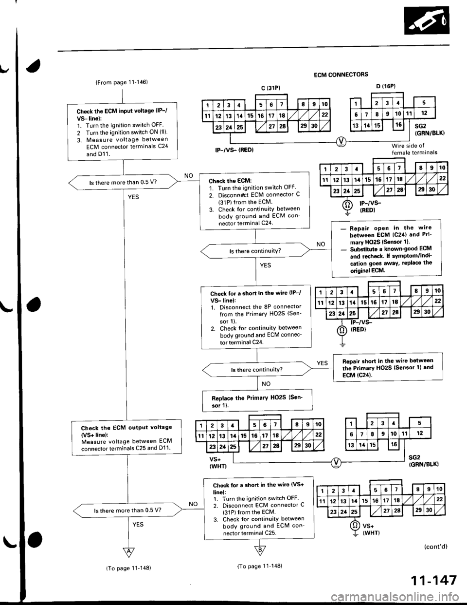
Check the ECM input vottage {lP-/
VS- lino):1. Turn the ignition switch OFF.
2 Turn the ignition switch ON (ll)
3. Measure voltage between
ECM connector terminals C24
Ch.ck the ECM:
1. Turn the ignition switch OFF
2. Disconndct ECM connector C
{31P){rom the ECM.
3. Check lor continuity between
body ground and ECM con
nector terminal C24
ls there more than 0.5 V?
- Repair open in the wire
betw€en ECM {C2{l and Pri-
ma.y HO2S {S€nsor 1 l.- Substitute a known-good ECM
and recheck. It symptom/indi
cation goes away. replace the
odginal ECM.
Check to. r short in the wi.e {lP-/
VS- lin6l:1. Disconnect the 8P connector
from the Primary HO2S lsen-
sor 1).2. Check tor continuity between
body ground and ECM connec-
tor terminal C24
Ropair short in the wire bstween
the Primary HO2S lsensor 1) and
ECM (C24).
Check the ECM output voltage
{VS+ linel:N4easure voltage between ECM
connectorterminals C25 and D11.
Check for a short in the wire (VS+
line):1. Turn the ignition switch OFF.
2. Disconnect ECM connector C
{31P) Irom the ECM.
3. Check {or continuity between
body ground and ECM con
nector terminal C25.
ls there mote than 0.5 V?
ECM CONNECTORS
lFrom page'11-146)c (31PlD {15P)
tP-/vs- tREolfemale termrnals
sG2(GRN/BLKI
(cont'd)
11-147
I23a68910
111213la15t6'171622
232a25272a2930
O rP-/vs-:Z taeot
,l23a55I910
1112131a151617t822
232125212AE30
0) {REDr
23a518910
l11213ta'15't6171822
2321E272A2930
[]) vs*I rwsrt
(To page 11- 148)(To page 11 148)
Page 417 of 2189
PGM-FI System
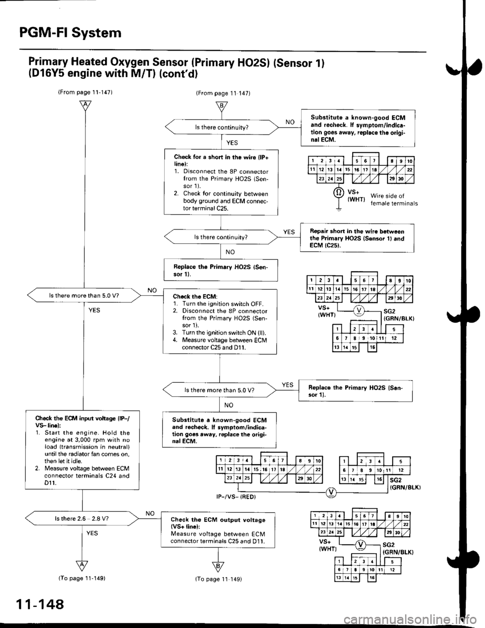
Primary Heated Oxygen Sensor (Primary HO2SI (sensor l)
(Dl6Y5 engine with M/T) (cont'd)
(From page 1l-147)(From page 11 147)
(To page 11 149)
{GRN/BLK}
(GRN/8I-K}
(To page 11-149)
11-148
Substitute a known-good ECMand rechock. tf symptom/indicr-tion goes away, replace the origi-nalECM.
Check for a short in the wire llP+lin6):1. Disconnect the 8P connectorIrom the Primary HO2S (Sen-
sor 1).2. Check tor continuity betweenbody ground and ECM connec-tor terminal C25.
Repair short in the wiro botweenthe Primarv HO2S {Sensor 1} andECM {C25}.
Replace th€ Primary HOzS {Sen-sor 11.
| 2 3ra1a9to
tl 12t516111a
p ffi;r, w''.""i0"or.I lemate lerml
ls there more than 5.0 V?check the EcM:1. Turn the ignition switch OFF.2. Disconnect the 8P connectorfrom the Primary HO2S (Sen-
sor 1).3. Turn the ignition switch ON (ll).4. Measure voltage between ECN4connector C25 and D11.
ls there more than 5.0 V?
Check the ECM input voltage llP-/vS-linel:1. Start the engine. Hold theengine at 3,000 rpm with noload (transmission in neutral)untilthe radiator fan comes on,then let it idle.2. Measure voltage between ECMconnector terminals C24 andDt1.
Subslitute a known-good ECMand rgcheck. It symptom/indica-tion goes away, repl.ce the origi-nal ECM.
ls there 2.6 2.8 V?Check th6 ECM output voltage(VS+ linel:Measure voltage between ECMconnector terminals C25 and D11.
7a9t0It 12t3t6'11ta
VS+{WHT}sG2
235
,9 ,101l12
l3'tat515
1 2i35a9t0't2'ttt5ttrl22
VS+{WHT)sG2
23
6lt9ll1315
Page 418 of 2189
(From page 11 148)(From page 11'148)
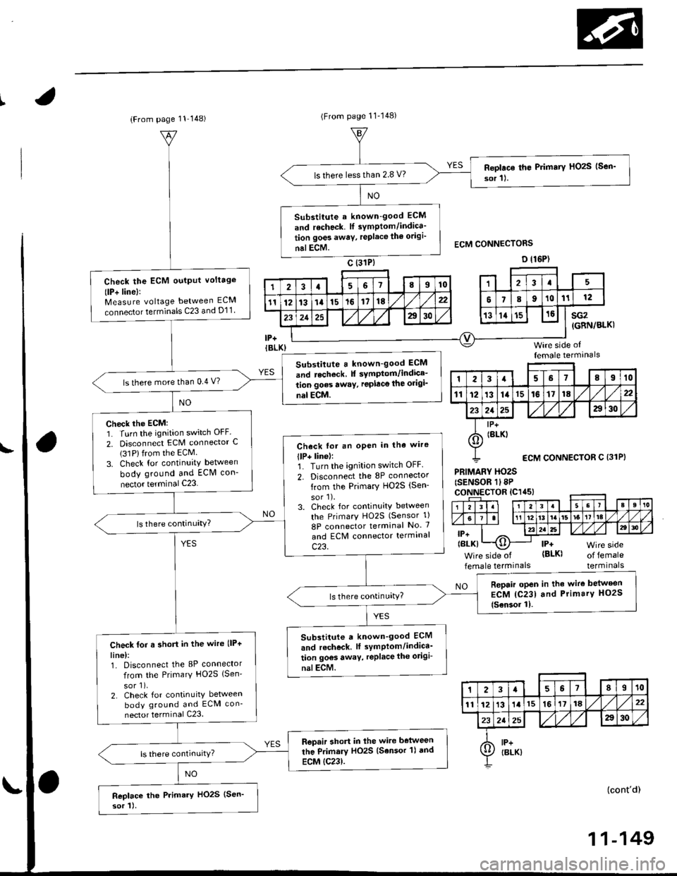
Roplac€ th€ Primary HOzS (Sen'
sor 11.ls there lessthan 2.8 V?
Substitute a known-good ECM
and recheck. lf symptom/indica'
tion goes awav, replace th€ odgi'
nalECM.
Check the ECM oulput voltage
(lP+ linel:Measure voltage between ECM
connector terminals C23 and D11
Substitute a known-good ECM
and recheck f symptom/indica-
tion goes awaY, replace the origi_
nal ECM.
ls there more than 0.4 V?
Check the ECM:1. Turn the ignition switch OFF.
2. Disconnect ECM connector C(31Plfrom the ECM.
3. Check for continuity between
body ground and ECM con-
nector terminal C23
Check fot an oPen in tha wire
llP+ linel:1. Turn the ignition switch OFF.
2. Disconnect the 8P connoctor
from the Primary HO2S (Sen-
sor'l).3. Check for continuity between
the PrimarY HO2S (Sensor 1)
8P connector terminal No. 7
and ECM connector termrnal
c23.
Repair open in the wire belween
ECM {C231 and Primary HO2S
{Sensor 11.
Substitute a known_good ECM
and r6check. lf symPlom/indica'
tion goos away, replace the odgi-
nalECM.
Check for a short in the wire llP+
line):1. Disconnect the 8P connector
from the Primary HO2S {Sen'
sor 1),2. Check for continuity between
body ground and ECM con-
nector terminal C23.
Repair short in lhe wire belween
the Primary HO2S (Sensor 'l) dnd
ECM {C23).
Replace the Primary HO2S (Sen'
sor 1).
sG2(GRN/BLKI
Wire side offemale termanals
PRIMARY HO2S(SENSOR 1l8PcoNNECTOR lC1a5l
lP+(BLK)
Wire side of
female termrnalsof femaleterminals
NO
(cont'd)
123a68910
111213141516171822
2125a30
I lP+
6) tBrK)
ECM CONNECTOR C {31P}
23a67II10
1112131l15161118,422
232a25A30
A lP+Ij/ IBLK)
11-149
Page 419 of 2189
PGM-FI System
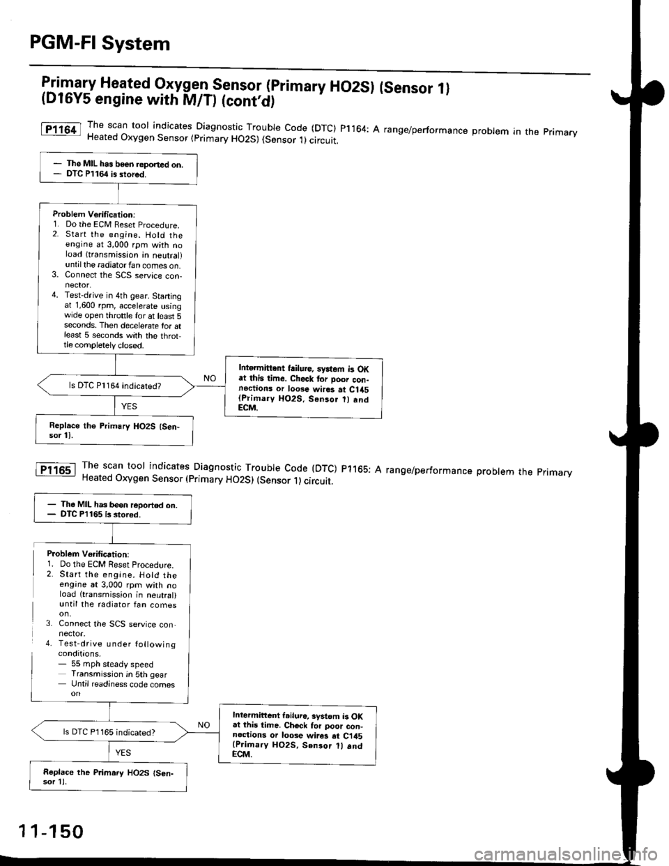
l:in1.".fy Heated Oxygen Sensor (primary HO2SI (sensor 1l(D16Y5 engine with M/D (cont'd)
The scan toor indicates Diagnosti" -Tl:y|* code (DTC) pl164: A range/performance probrem in the primaryHeated Oxygen Sensor (primary HO2S) (Sensor 1)circuit.
The scan tool indicates Diagnostic Trouble Code (DTC) p1165: AHeated Oxygen Sensor (primary HO2S) (sensor 1) circuit.
range/performance problem the pnmarv
The MIL has beon reponed on.DTC P1164 is stored.
Problem Verilication:1. Do the ECM Beset Procedure.2. Start the engine. Hold theengine at 3,000 rpm with noload (transmission in neutral)untilthe radiatorfan comes on.3. Connect the SCS service con-nector.4. Test-drive in 4th gear. Startingat 1,600 rpm, accelerate usingwide open throttle for at least 5seconds. Then decelerate tor atleast 5 seconds with the throttle completely closed.
Intgrmittent failure, syrtem b OKat this time. Check tor Door con-noctions or loose wires at C1a5(Primary HO2S. Senso.
andECM.
ls DTC Pl164 indicatedT
- The MIL has been reoorted on.- DTC P1165 is stored.
Intermittent l.iluro, system b OKat lhis time. Ch€ck tor poor con-noctions or loose wir6 at Ci45(Prioary HO2S, Sen3or 1l .ndECM.
ls DTC P1165 indicated?
Replace the P.imary HO2S (S6n-sor 11.
Problem Vo.ification:1. Do the ECM Reset Procedlre.2. Start the engine. Hotd theengine at 3,000 rpm with noload (transmission in neutral)until the radiator fan comes
3. Connect the SCS service con,nector.4. Test-drive u nder followingconditions.- 55 mph steady speedTransmission in 5th gearUntil readiness code comes
1 1-150
Page 420 of 2189
t
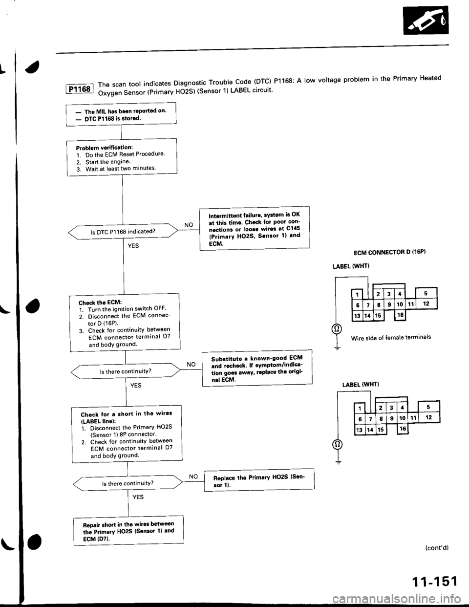
The scan tool indicates Diagnostic Trouble Code (DTC) P1168; A low voltage problem in the Primary Heated
Oxygen Sensor (Primarv Ho2S) (Sensor 1) LABEL circuit'
- The MIL has b6€n reponed on'
- DTC P1168 is storcd
Problem vedfication:
1. Do the ECM Reset Procedure
2. Start the engine.
3. Wait at least two minutes
lntalmittent failure' aYstom b OK
at thi3 time. Chock lor Poor con-
nection3 or loo3o wiro3 at C145
(Primary HO2S, S.n.or 1l and
ECM.
ls DTC P1168 indicated?
Chock th. ECM:
1. Turn the ignition switch OFF.
2. Disconnect the ECM connec'
tor D 116P).3. Check for continuity between
ECM connector terminal D7
and body ground
Sub3titut. e known-good ECM
6nd r.chock. lf rymptom/indica-
tion gocr away, r.Placs the origi_
nal ECM.
Check for t shott in lhg wire3
ILABEL line):1. Disconnect the Primary HO2S
(Sensor 1) 8P connector'
2. Check for continuitv between
ECM connector terminal D7
and body ground
Reoair short in the wir63 botlvoon
lhe Primary HO2S {Sensor 1} end
ECM (O71.
ECM CONNECTOR D {16PI
LABEL {WHTI
wire side of female terminals
LABEL (WHTI
(cont'd)