Section 11 HONDA CIVIC 1998 6.G Repair Manual
[x] Cancel search | Manufacturer: HONDA, Model Year: 1998, Model line: CIVIC, Model: HONDA CIVIC 1998 6.GPages: 2189, PDF Size: 69.39 MB
Page 460 of 2189
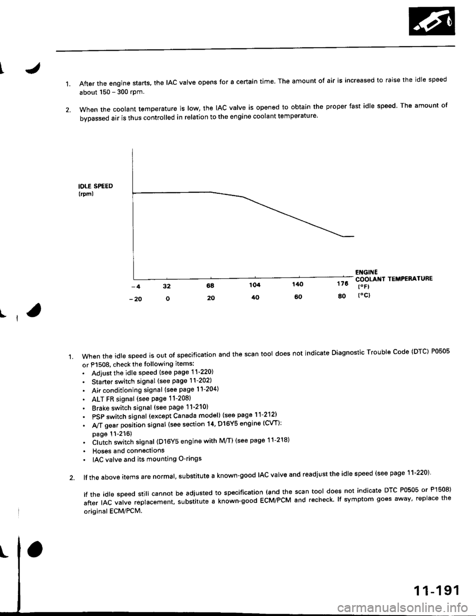
1.After the engine starts, the lAc valve opens for a certain time. The amount of air is increased to raise the idle speed
about 150 - 300 rpm.
When the coolant temperature is tow, the IAC valve is opened to obtain the proper fast idle speed. The amount of
bypassed air is thus controlled in relation to the engine coolant temperature'
IOLE SPEED
lrpml
176
80
ENGI ECOOLANI TEMPERATURE
t" Fl
toc)
ll
't.Whentheid|espeedisoutofspeciiicationandthescantoo|doesnotindicateDiagnosticTroub|ecode(DTc)P0505
or P1508. check the following items:
. Adiust the idle speed {see page 11-220}
. Starter switch signal (see page 11-202)
. Air conditioning signal (see page l1-204)
. ALT FR signal (see Page 11-2081
' Brake switch signal (see page 11-210)
. PSP switch signal (excapt Canada model) (see page 11-212)
. A,/T gear position signal {see section 14, Dl6Y5 engine (CVT):
page 11-216). Clutch switch signal (D16Y5 engine with M/T) (see page 11-218)
. Hoses and connections
' IAC valve and its mounting O-rings
lf the above items are normal, substitute a known-good IAC valve and readjust the idle speed (see page 11-220)
|ftheid|espeedsti||cannotbeadjustedtospecification(andthescantoo|doesnotindicateDTcP0505orP]50S)
after IAC valve replacement. substitute a known-good ECM/PCM and recheck. lf symptom goes away, replace the
original ECM/PCM.
Page 473 of 2189
ldle Gontrol System
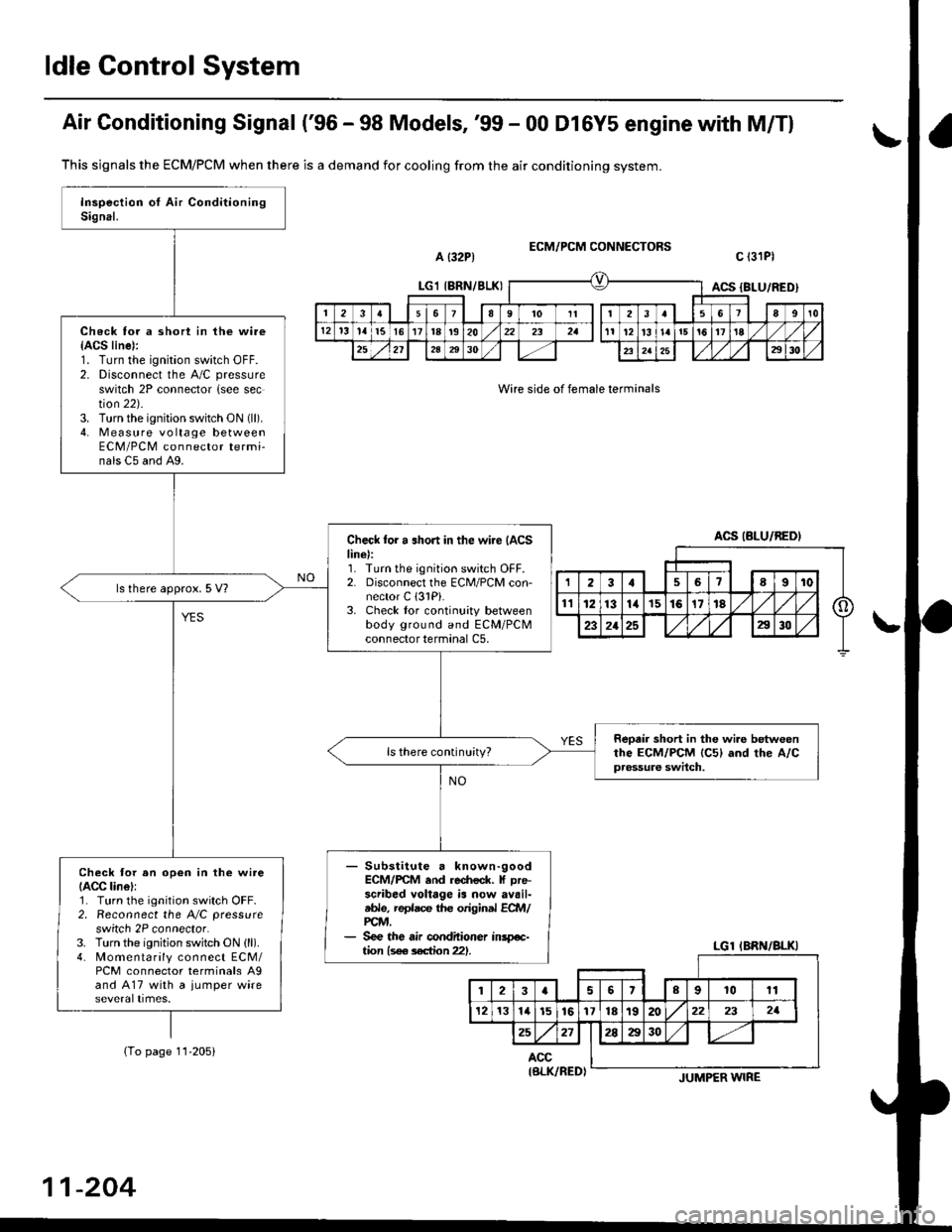
Air Gonditioning Signal ('96 - 98 Models, '99 - 00 Dl6Y5 engine with M/Tl
a {32P1ECM/PCM CONNECTORS
Wire side of female terminals
c l3lPl
This sjgnals the ECM/PCM when there is a demand for cooling from the air conditioning system.
(To page 11-205)
Check for a short in the wire{ACS line):1. Turn the ignition switch OFF.2. Disconnect the A/C pressure
switch 2P connector {see section 22).3. Turn the ignition switch ON (ll).
4. Measure vo lta ge betweenECM/PCM connector termi-nals C5 and A9.
Check for a .hort in the wi.e {ACSline):1. Turn the ignition switch OFF.2. Disconnect the ECM/PCM con-nector C (3lPi.
3. Check tor continuity betweenbody ground and ECM/PCMconnector terminal C5,
ls there approx. 5 V?
Reotir short in the wi.e betweenthe ECM/PCM lc5l and rhe A/Cpressure switch.
ls there continuity?
- Substitute a known-goodECM/rcM .nd re.fieck. f Dre-scribed voltage is now availtble, replace the original ECft4/PCM,- See the air conditioner inspe-tion ls€e s€ction 221.
Check tor an op€n in the wireIACC lin6l:1. Turn the ignition switch OFF.2. Reconnect the A/C pressure
switch 2P connector.3. Turn the ignition switch ON (ll).
4. Momentarily connect ECM/PCM connector terminals A9and A17 with a jumper wire
LGl IBRN/8LKIACS {BLU/RED)
2361I9't0Itt3a89t0
12't31al5l617t8t920232all12l3l!ai5!617'tE
252l2A2930232a252930
ACS (BLU/BEDI
LGl IBRN/BLKI
123aslslrl lolgl ro lrr I
121314l516y)nltslnl/@) zr I zr I
25271!M1 1-/r
ACC
11-204
IBLK/RED)JUMPER WIRE
Page 476 of 2189
I
JUMP€RWIRE
UNDER-HOOO FUSE/RELAYsox 9P coNNEcroR lca52l
123a
5689
ACC (8LK/REDI
Wire side ofterminals
ECM/PCM CONNECTORS
A (32P1
female
Wire side of {emale terminals
(From page 11-206)
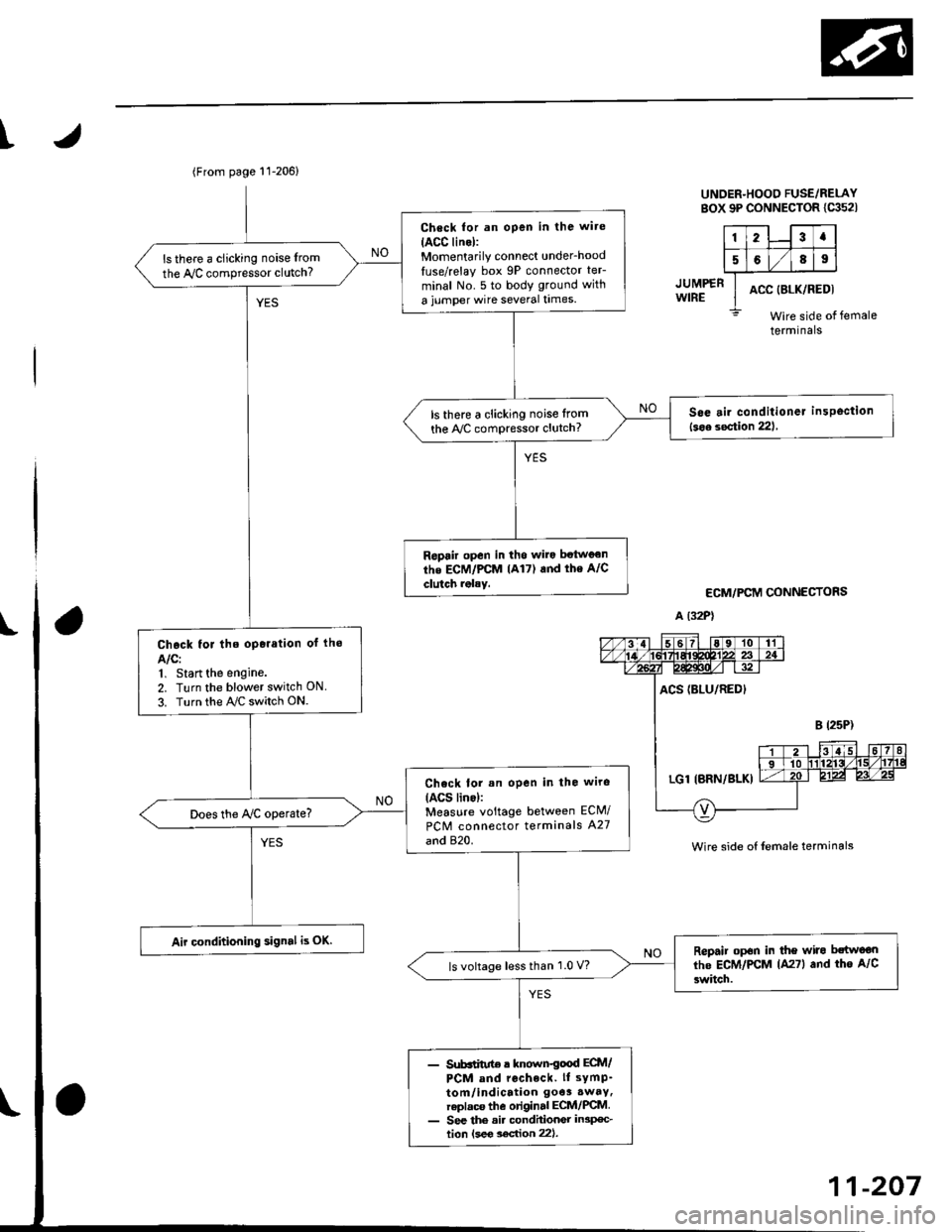
Check for an open in the wite
IACC lino):Momentarily connect under_hood
luse/relay box 9P connector teF
minal No. 5 to body ground with
a jumper wire several times.
ls there a clicking noise from
the Iy'C compressor clutch?
S6e air conditioner insPoction
l3oa section 221ls there a clicking noise lrom
the ly'C compressor clutch?
Ropair open in tho wilo betwg€n
the ECM/PCM lA17) and the A/C
clutch rolay.
Chock for the oporation of lho
AIC:1, Start the engine.
2. Turn the blower switch ON
3. Turn the ray'C switch ON.
Check lor an open in the wiro(ACS lino):Measure voltage between ECM/
PCM connector terminals A27
and 820.
Does the Iy'C operate?
Air conditioning signal is OK.Repair op6n in the wiro bctwoon
lhe ECM/PCM lA27l and tho A/C
3witch.ls voltage lessthan 1.0 V?
- Sub6iitut€ r known€ood ECtt /PCM and rccheck. ll sYmP-
tom/indication 9oe3.waY,replaca the original ECM/PCM- See the ai. condhionGr in3p€c-tion lsee soc{ion 221.
11-207
Page 479 of 2189
ldle Control System
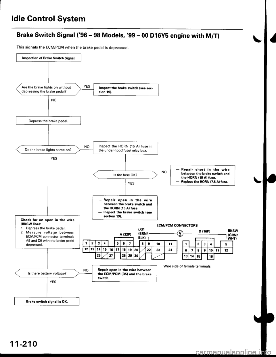
Brake Switch Signal ('96 - 98 Models, '99 - 00 Dl6YS engine with M/Tl
This signals the ECM/PCM when the brake pedal is deoressed.
LGlBKSW(GRN/WHTI
D {16P)
Wire side of female t€rminals
Inspection of Brake Switch Signal.
Are the brake lights on withoutdepressing the brake pedal?
Depress the brake pedal.
Inspect the HORN (15 A) fuse inthe under-hood fuse/ relay box.Do the brake lights come on?
- Repair short in the wirebetween the brake 3whch andrhe HORN 115 At lu3e.- Replace the I|oRN 17.5 A) tus€.
Repair open in the wirebetween the brake switch andthe HORN 115 Al fuse.Inspect th6 br.ke switch {s6€section l9l.Check tor an open in the wireIBKSW line):1. Oepress the brake pedal.2. Measure voltage betweenECM/PCNI connector terminalsAg and D5 with the brake pedaloepresseo.
Repair open in the wire b€tweenthe ECM/PCM {Dsl and the brakeswitch.
ls there battery voltage?
Brakc switch sign.l is OK.
ECM/PCM CONNECTOFS
A (32PtIBRI\v
,la678101112I
121311151617t8192022232aI9101112
25212Aa3013141516
11-210
Page 480 of 2189
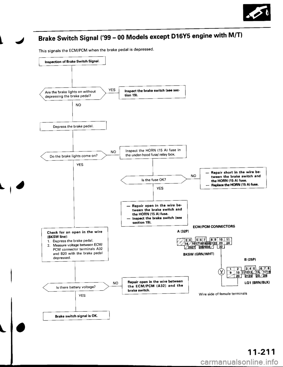
IJBrake Switch Signal ('99 - 00 Models except Dl6Y5 engine with M/Tl
This signals the ECM/PCM when the brake pedal is depressed
I
lnsoection ot Brake Switch signal.
Are the brake lights on without
depressing the brake Pedal?
Depress the brake Pedal
Inspect the HoRN {15 A} fuse in
the underhood fuse/ relay box'Do the brake lights come on?
- R.pair short in the wiro be'
tween the brake switch and
the HORN (15 Alfuse.- Replac€ the HORN (15 A) tuse.
- Repair open in the wite be'
tween the brako switch and
the HORN (15 Alfuse.- lnsoect the brake switch (3ec
section tgl.
Check fot an oPen in the wire
{BKsw linel:
1. Depress the brake Pedal.2. Measure vohage beween ECM/
PCM connector terminals A32
and 820 with the brake Pedaldepressed.
Bepair open in the wire between
the ECM/PCM (A32) and the
brake switch.
Brake switch signal i5 OK
ECM/PCM CONNECTORS
BKSW (GRN/WHTI
LG1 {BRN/BLK)
Wire side o{ female terminals
Page 489 of 2189
ldle Control System
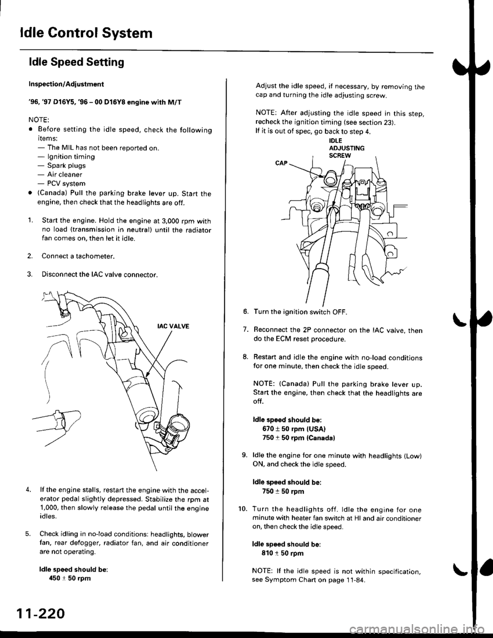
ldle Speed Setting
Inspection/Adiustmenl
'96, '97 Dl6Y5. '96 - 00 Dl5Y8 sngine with M/T
NOTE:
. Before setting the idle speed, check the following
items:- The MIL has not been reported on.- lgnition timing- Spark plugs- Air cleaner- PCV system
o (Canada) Pull the parking brake lever up. Start the
engine, then check that the headlights are off.
1. Start the engine. Hold the engine at 3.000 rpm withno load (taansmission in neutral) until the radiatorfan comes on, then let it idle.
2. Connect a tachometer.
3. Disconnect the IAC valve connector.
4.lf the engine stalls, restart the engine with the accel-
erator pedal slightly depressed. Stabilize the rpm at1,000, then slowly release the pedal until the engineidles.
Check idling in no-load conditionsr headlights. blowerfan. rear defogger, radiator fan, and air conditioner
are not operating.
ldle spsed should be:
450 1 50 rpm
11-220
Adjust the idle speed, if necessary, by removing thecap and turning the idle adjusting screw.
NOTE; After adjusting the idle speed in this step,recheck the ignition timing (see section 23).
lf it is out of spec, go back to step 4.
IDLE
6. Turn the ignition switch OFF.
7. Reconnect the 2P connector on the IAC valve, then
do the ECM reset procedure.
8. Restart and idle the engine with no-load conditionsfor one minute, then check the idle speed.
NOTE: (Canada) Pull the parking brake lever up.Start the engine, then check that the headlights areoff.
ldle sp€sd should b€:
670 i 50 rpm IUSA)750 t 50 rpm {Canada}
9. ldle the engine tor one minute with headlights {Low)ON. and check the idle speed.
ldle speed should be:
750 :r 50 rpm
10. Turn the headlights off. ldle the engine for oneminute with heater fan switch at Hl and air conditioneron, then check the idle speed.
ldle speed should be:
810150 rpm
NOTE: lf the idle speed is not within specification,see Symptom Chan on page 11-84.
Page 491 of 2189
ldle Control System
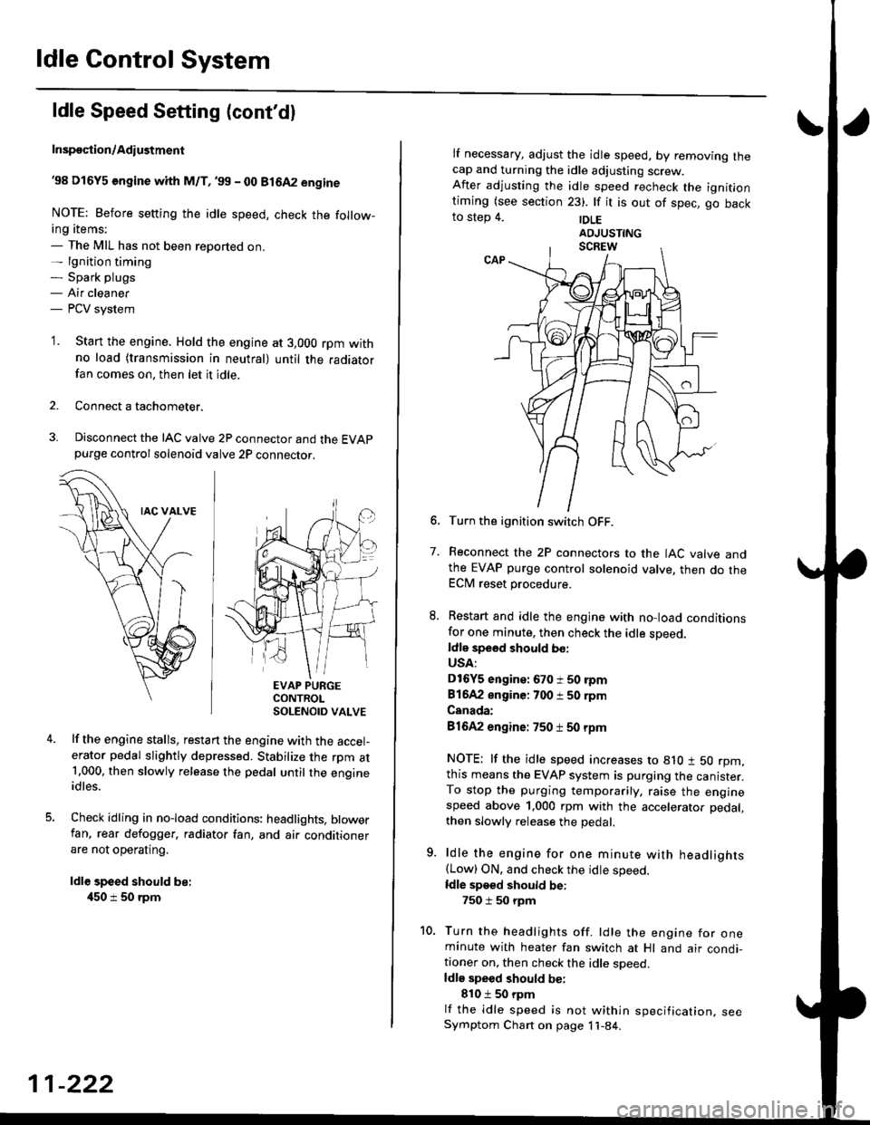
ldle Speed Setting (cont'dl
Inspeqtion/Adiustment
38 D16Y5 engine whh M/T,'99 - 00 81642 engine
NOTE: Before setting the idle speed, check the follow-ing items;- The MIL has not been reported on.- lgnition timing- Spark plugs- Air cleaner- PCV system
'1. Start the engine. Hold the engine at 3,000 rpm withno load (transmission in neutral) until the radiatorfan comes on, then let it idle.
Connect a tachometer.
Disconnect the IAC valve 2P connector and the EVAPpurge controlsolenoid valve 2P connector.
EVAP PURGECONTROLSOLENOID VALVE
lf the engine stalls, restart the engine with the accel-erator pedal slightly depressed. Stabilize the rpm at1.000, then slowly release the pedal until the engineidles.
Check idling in no-load conditions: headlights, blowerfan, rear defogger, radiator fan, and air conditionerare not operating.
ldl€ speed should be:
450 i 50 rpm
11-222
lf necessary, adjust the idle speed, by removrng lnecap and turning the idle adjusting screw.After adjusting the idle speed recheck the ignitlontiming (see section 23). lf it is out of spec, go backto step 4. |DLE
6. Turn the ignition switch OFF.
7. Reconnect the 2P connectors to the IAC valve andthe EVAP purge control solenoid valve, then do theECM reset procedure.
8. Restart and idle the engine with no-load conditionsfor one minute, then check the idle sDeed.ldle speed should bo:
USA:
D16Y5 engine: 670 i 50 rpm
81642 engine: 700 i 50 rpm
Canada:
81642 engine: 750 t 50 rpm
NOTE: lf the idle speed increases to 8lO t 50 rpm,this means the EVAP system is purging the canister.To stop the purging temporarily, raise the enginespeed above 1,000 rpm with the accelerator pedal,
then slowly release the pedal.
9. ldle the engine for one minute with headlights(Low) ON. and check the idle speed.
ldle speed should be:
750 i 50 rpm
10. Turn the headlights off. ldle the engine for oneminute with heater fan switch at Hl and air condi-tioner on, then check the idle soeed.ldls speed should be:
810 t 50 rpm
lf the idle speed is not within specification, seeSymptom Chart on page 11-84.
Page 505 of 2189
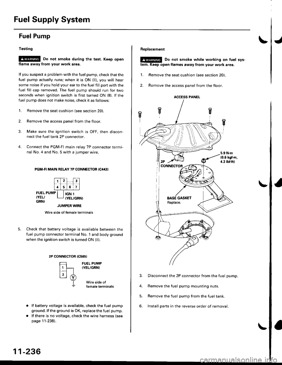
Fuel Supply System
Fuel Pump
Testing
!@ Do not smoke during the test, Keep open
flame away from your work atea,
lf you suspect a problem with the fuel pump, check that the
fuel pump actually runs; when it is ON (ll), you will hear
some noise if you hold your ear to the fuel fill port with the
fuel fill cap removed. The fuel pump should run for two
seconds when ignition switch is first turned ON (ll). lf the
fuel pump does not make noise, check it as follows:
L Remove the seat cushion {see section 20).
2. Remove the access panel from the floor.
3. Make sure the ignition switch is OFF, then discon-
nect the Iueltank 2P connector.
4. Connect the PGM-FI main relay 7P connector termi-
nal No. 4 and No. 5 with a jumper wire.
PGM-R MAIN RELAY 7P CONNECTOR lC4,(|l
FUEL PUMP
IYEL/GRN}
IGN 1(YEL/GRNI
tcs6s)
FUEL PUMP(YEL/GRNI
Wire side oftemale torminals
JUMPER WIRE
Wire side of temale terminals
Check that battery voltage is available between the
fuel pump connector terminal No. 1 and body ground
when the ignition switch is turned ON (ll).
CONNECTOR
=
[t
L3l .i)
T
lf battery voltage is available, check the fuel pump
ground. lf the ground is OK, replace the fuel pump.
lf there is no voltage, check the wire harness (see
page 11-238).
11-236
Replacement
@E Do not smoke while working on tuel svs-
tem. Keep open llames away from your work area.
1. Remove the seat cushion (see section 20).
2. Remove the access panel trom the floor.
3. Disconnect the 2P connector from the fuel pump.
4. Remove the fuel pump mounting nuts.
5. Remove the fuel pump from the fuel tank.
6. Install pans in the reverse order of removal.
ACCESS PANEL
i
Page 510 of 2189
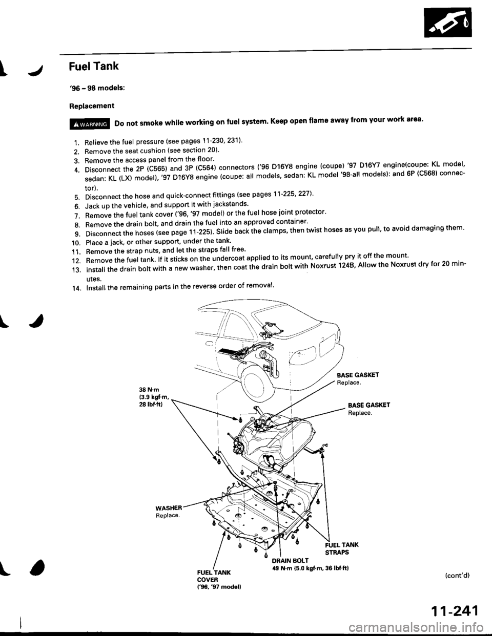
IFuelTank
'96 - 98 models:
Replacement
I
1. Relieve the fuel pressure (see pages \1-230' 23'll'
2. Remove the seat cushion (see section 20).
3. Remove the access panel from the floor'
4. Disconnect the 2P (C565) and 3P (C564) connectors ('96 D]6Y8 engine (coupe) '97 D16Y/ engine(coupe: KL model'
sedanKL(LX)model).'97D'l6YSengine(coupe:allmodels'sedan:KLmodel'98-allmodels):and6P(C568)connec-
tor),
5. Disconnect the hose and quick-connect fittings (see pag es'l'l-225' 2271
6. Jack up the vehicle, and support it with jackstands'
7. Removethefuel tank cover ('96,'97 model) orthefuel hose joint protector'
8. Bemovethedrain bolt,and drainthefuel into an approved container'
9. Disconnect the hoses {see page r i-izst. Sria" nu"i ihe clamps, then twist hoses as you pull, to avoid damaging them'
10. Place a jack. or other support, under the tank'
11. Remove the strap nuts, and let the straps fall free'
12. Removethefuel tank lf it sticks on the undercoat applied to its mount' caref u lly pry it off the mount'
13.|nsta||thedrainbo|twithanewwasher.thencoatthedrainbo|twithNoxrustl24B,A||owtheNoxrustdryfor20min-
ules.
14. Installthe remaining pans in the reverse order of removal'
SASE GASKETReplace.
BASE GASKETReplace.
!@@ Do not smoke while working on fuel system' Keep open flame away from your work ar'a'
TANKSTRAPS
DRAIN BOLT,19 N.m {5.0 kgt m, 36 lbf.ftl(cont'd)
11-241
Page 511 of 2189
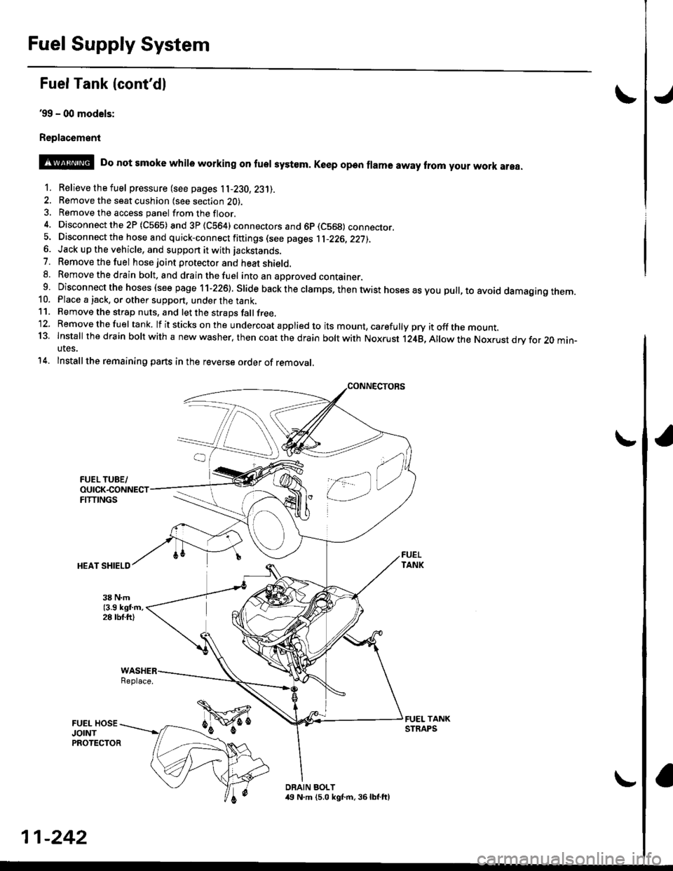
Fuel Supply System
Fuel Tank {cont'dl
39 - (xt models:
Replac6ment
o
@ Do not smoke whire working on fuer system. Ke€p open frama away trom your work area.
1. Relievethefuel pressure (see pages 11-230,23'll.
2. Remove the seat cushion lsee section 2O).3, Remove the access panel fromthefloor.
4. Disconnectthe2P (C565) and3P(CS64) connectors and 6p (C569) connecror.5. Disconnect the hose and quick-connect fiftings (see pages 1l-226,22j),6. Jack up the vehicle, and support it with jackstands.
7. Removethefuel hose joint protector and heat shield.8. Removethedrain bolt. and drainthefuel intoan aporoved container.9 Disconnect the hoses (see page 11-226). Slide back the clamps. then twist hoses as you pull, to avoid damagtng rnem.10. Place a jack, or other support, under the tank,11. Remove the strap nuts, and let the straps fallfree,'12. Removethefuel tank. lf itsticks onthe undercoat applied to its mount, carefully pry itoffthe mount.13. Install thedfain boltwith a new washer. then coat the d rain bolt with Noxrust 124B,Allowthe Nox.ust drv for 20 min-utes.
14. Installthe remaining parts in the reverse order of removal,
Replace.
DRAIN BOLT,19 N.m (5.0 kgf.m, 36lbf.ft)
11-242