boot HONDA CIVIC 1998 6.G Repair Manual
[x] Cancel search | Manufacturer: HONDA, Model Year: 1998, Model line: CIVIC, Model: HONDA CIVIC 1998 6.GPages: 2189, PDF Size: 69.39 MB
Page 1136 of 2189
Front Suspension
Knuckle/Hub Replacement (cont'dl
NOTE: Use the special tool to separate the ball joints
from the suspension or steering arm,
CAUTION: 86 careful not lo damage the ballioint boot.
12. Clean any din or grease off the ball joint.
13. Remove the cotter pin from the steering arm, and
remove the nut.
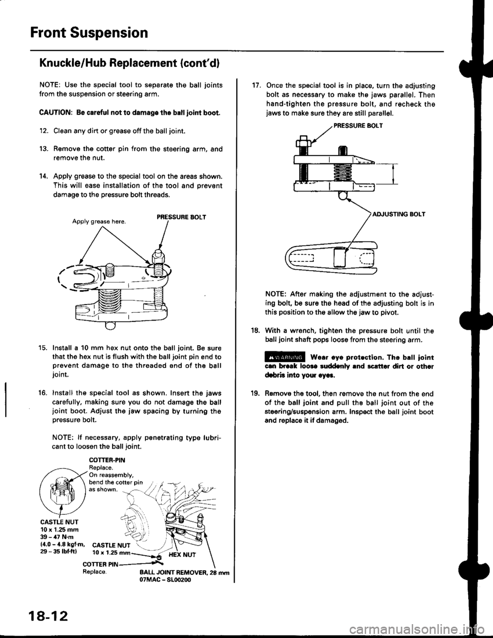
14. Apply grease to the special tool on the areas shown,
This will ease installation of the tool and prevsnt
damage to the pressure bolt threads.
PRESSURE AOLT
Install a 10 mm hex nut onto the ball joint. Be sure
that the hex nut is flush with the ball joint pin end toprevent damage to the threaded end of the balljoint.
Install the special tool as shown. Insert the jaws
carefully, making sure you do not damage the balljoint boot. Adiust the iaw spacing by turning th6pressure bolt.
NOTE: lf necessary, apply penetrating type lubri-
cant to loosen the ball joint.
COTTER.PINReplace.On reassembly,bend the cofter pin
15.
16.
CASTI.T NUT10 x 1,25 mm39 - 47 N.m14.0 - 4.8 kgf.m,29 - 3s tbl.fttCASTLE NUT10 r 1.2s mn--]*-
corrcn nn .\
18-12
Replace-
17. Once the special tool is in place, turn ths adjusting
bolt as necessary to make the jaws parallel. Then
hand-tighten the pressure bolt, and recheck thejaws to make sure they are still parallel.
AI\IUSTING BOLT
NOTE: After making the adiustment to the adiust-
ing bolt, be sure the head of the adjusting bolt is in
this position to the allow the jaw to pivot.
With a wrsnch, tighten the pressure bolt until the
ball joint shaft pops loose from the steering arm.
E@ we.r cye plotection. Thc brtt iointcln brcrk loose suddenly and sclt'tol dirt or other
d.brb inio youl .ye..
Rsmov€ the tool, then remove th€ nut from the end
of the ball ioint and pull the ball joint out of the
stoering/suspension arm. Insp€ct the ball joint boot
and replace it if damaged.
18.
10
Page 1139 of 2189
I
NOTE: Wash the knuckle and hub thoroughly in
high flash point solvent before reassembly.
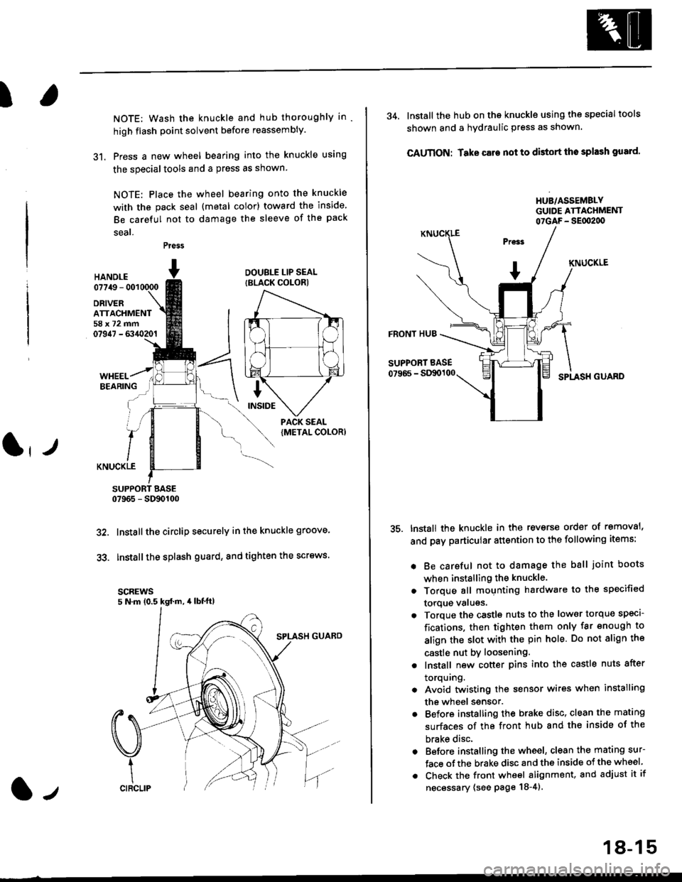
31. Press a new wheel bearing into the knuckle using
the specialtools and a press as shown
NOTE: Place the wheel bearing onto the knuckle
with the pack seal (metal color) toward the inside
Be careful not to damage the sleeve of the pack
seal.
Press
HANOI.E07749 - 001
DRIVERATTACHMENT58x72mm07947 - 6340201
DOUBLE LIP SEAL
{BLACK COLOR)
KNUCKLE
SUPPORT BASE07965 - SD90100
Installthe circlip securely in the knuckle groove'
Installthe splash guard, and tighten the screws.
scREws5 N.m (0.5 kgd m, 4lbt'ft)
32.
33.
l-,
18-15
34. lnstall the hub on the knuckle using the specialtools
shown and a hydraulic press as shown.
CAUTION: Take care not to distort tho splash gusrd'
HUB/ASSEMBLYGUIDE ATTACHMENT07GAF- SEflt2d)
KNUCKLE
FRONT HUB
SUPPORT BASE
07966 - StXx)100SPLASH GUARD
tnstall the knuckle in the reverse order of removal'
and pay particular attention to the following items:
. Be careful not to damage the ball joint boots
when installing the knuckle.
. Torque all mounting hardware to the specified
torque valugs.
. Torque the castls nuts to the low€r torque specl-
fications, then tighten them only far enough to
align the slot with the pin hole. Do not align the
castle nut by loosening.
. lnstall new cotter pins into the castle nuts after
torquing.
. Avoid twistin0 the sensor wires when installing
the wheel ssnsor.
. Before installing the brake disc, clean the mating
surfaces of the front hub and the inside of the
brake disc.
. Before installing the wheel, clean the mating sur-
face ofthe brake disc and the inside of the wheel
. Check the front wheel alignment, and adjust it if
necessary (see page 18-4).
Page 1140 of 2189
Front Suspension
L
Lower Ball Joint Replacement
Remove the knuckle (see page 18-11).
Remove the boot by prying the set ring off.
Check the boot for deterioration and damage.
replace if necessary.
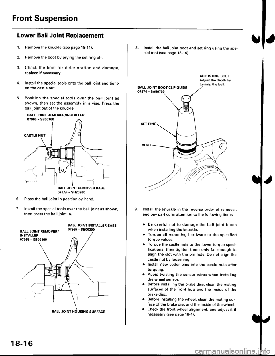
Install the special tools onto the ball joint and tight-
en the casfle nut.
Position the special tools over
shown. then set the assembly in
ball joint out of the knuckle,
BALL JOINT REMOVER/INSTALLER07965 - SB00r00
CASTLE NUT
the ball joint as
a vise. Press the
lf
7.
BALL JOINT REMOVER BASE07JAF - SH20200
Place the ball joint in position by hand.
Install the special tools over the ball joint as shown,
then press the ball joint in.
BALL JOINT INSTALLEB BASE07965 - 5800200
BALL JOINT HOUSING SURFACE
18-16
8. Install the ball joint boot and set ring using the spe-
cial tool (see page 18-16).
ADJUSTING BOLTAdjust rhe depth byturning the bolt.
Install the knuckle in the reverse order of removal,
and pay particular attention to the following items:
. Be careful not to damage the ball joint boots
when installing the knuckle,
. Torque all mounting hardware to the specified
torque values.
. Torque the castle nuts to the lower torque speci-
fications. then tighten them only far enough to
align the slot with the pin hole. Do not align the
castle nut by loosening.
. Install new cotter pins into the castle nuts after
torquang.
. Avoid twisting the sensor wires when installing
the wheel sensor.
. Before installing the brake disc. clean the mating
surfaces of the front hub and the inside of the
brake disc.
. Before installing the wheel, clean the mating sur-
face of the brake disc and the inside of the wheel.. Check the front wheel alignment, and adjust it if
necessary {see page 18-4).
Page 1141 of 2189
Front Damper
!Ball Joint Boot RePlacement
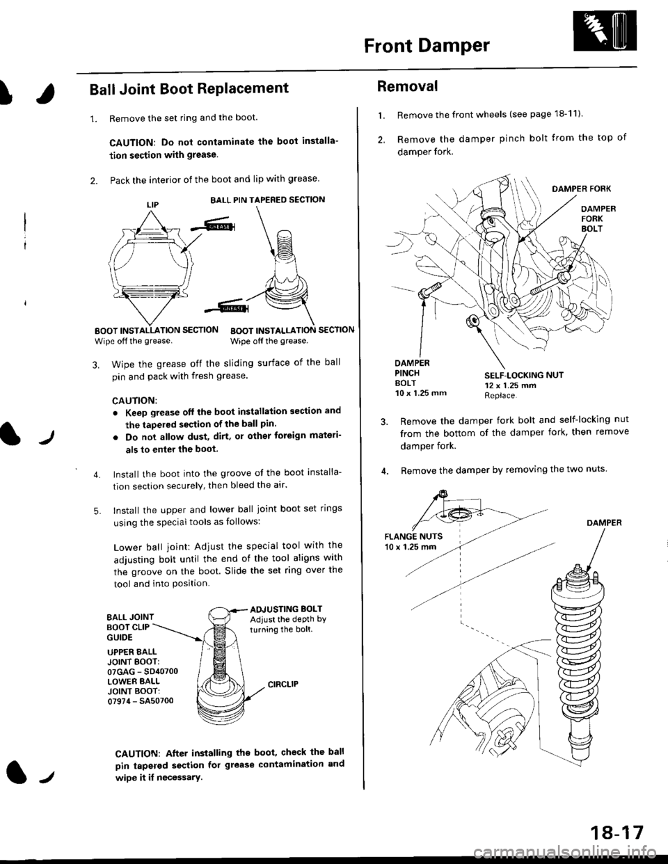
1.Remove the set ring and the boot.
CAUTION: Do not contaminate the boot installa-
tion section with grease.
Pack the interior of the boot and lip with grease
EALL PIN TAPERED SECTION
EOOT INSTALLATION SECTION
Wipe off the grease.BOOT INSTALLATION SECTION
Wipe off the grease.
lJ
3. Wipe the grease off the sliding surface of the ball
pin and pack with fresh grease.
CAUTION:
. Keep grease off the boot installation section and
the tapeled section of the ball pin.
5.
. Do not allow dust, dirt, or other toreign materi-
als to enter the boot.
Install the boot into the groove of the boot installa-
tion section securely, then bleed the atr.
Install the upper and lower ball joint boot set rings
using the special tools as follows:
Lower ball joint: Adiust the special tool with the
adjusting bolt until the end of the tool aligns with
the groove on the boot. Slide the set ring over the
tool and into Position.
BALL JOINTAOJUSTING BOLTAdjust the depth by
turning the bolt.BOOT CLIPGUIDE
4.
UPPER EALLJOINT EOOT:07GAG - SD40700LOWER BALLJOINT BOOT:07974 - SA50700
CAUTION: After installing the boot, check the ball
pin tapsrod section fol grease contamination and
wipe it if necessary.lt
18-17
Removal
l. Remove the front wheels (see page 18-11).
2, Remove the damper pinch bolt trom the top of
damper fork.
DAMPER FORK
OAMPERFORKBOLT
OAMPERPINCHAOLT10 x 1.25 mm
SELF-LOCKING NUT12 x 1.25 mmReplace.
Remove the damper fork bolt and self-locking nut
from the bottom of the damper fork, then remove
damper fork.
Remove the damper by removing the two nuts
DAMPER
Page 1152 of 2189
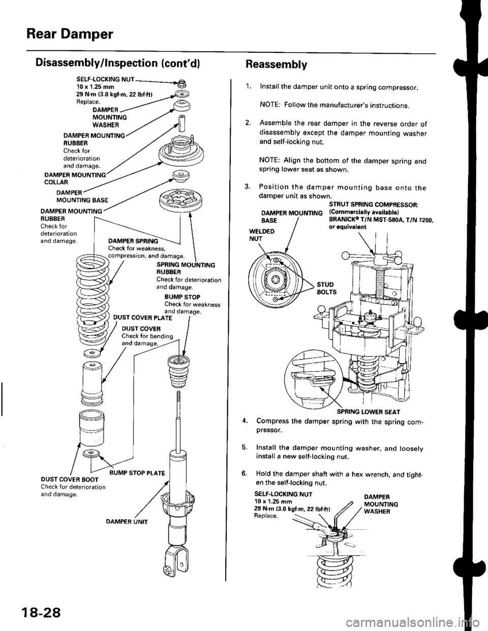
Rear Damper
Disassembly/lnspection (cont'dl
SELF-LOCK|NG NUT - el10 x 1.25 mm v
29 N.m {3.0 kst'm, 22 lbf.ftlReplace.
DAMPEBMOUNTINGWASHER
DAMPER MOUNTING8U8BERCheck tordeteriorationano oamage.
DAMPERCOLLAR
DAMPERMOUNTING BASE
OAMPER MOUNTING
DAMPER SPRINGCheck lor weakness,compression, and damage.
SPRING MOUNTINGRUBBERCheck for deteriorationano oamage.
BUMP STOPCheck for weaknessand damage,
BUBBESCheck fordeteriorationano oamage.
OUST COVER PLATE
DUST COVERCheck lor bending
DUST COVER BOOTCheck for deteriorationand damage.
18-2A
OAMPER UNITReplace. :
Reassembly
1.Install the damper unit onto a spring compressor.
NOTE: Followthe manufacturer's instructions.
Assemble the rear damper in the reverse order ofdisassembly except the damper mounting washer
and self-locking nut.
NOTE: Align the bottom of the damper spring andspring lower seat as shown.
Position the damper mounting base onto thedamoer unit as shown.
SIRUT SPRING COMPRESSOR:
DAMpERMOUNTTNG (Commerciattyavaitabtel
BRANICKO T/N MST-580A, T/N 7200.or cquivalont
Compress the damper spring with the spring com-pressor.
Install the damper mounting washer, and looselyinstall a new self-locking nut.
Hold the damper shaft with a hex wrench, and tight-en the self-locking nut.
SELF-LOCKING NUTDAMPER10 x 1,25 mm29 N m 13.0 kgt.m, 22 lbtftlMOUNTINGWASHER
Page 1158 of 2189
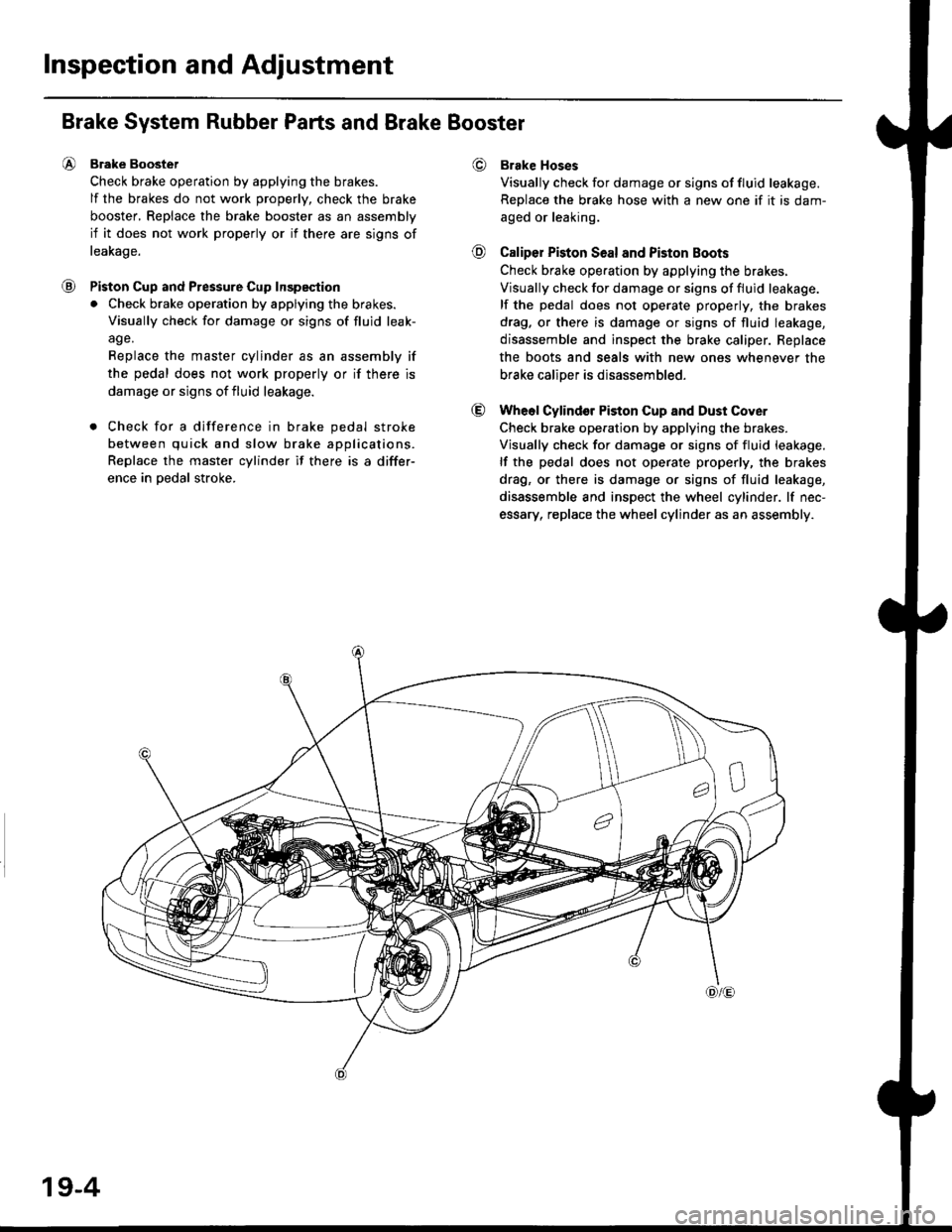
Inspection and Adjustment
€)
@
@
@
Brake System Rubber Parts and Brake Booster
Brake Boostet
Check brake operation by applying the brakes.
lf the brakes do not work properly, check the brake
booster, Replace the brake booster as an assembly
if it does not work properly or if there are signs of
leakage.
Piston Cup and Pressure Cup Inspeqtion
. Check brake operation by applying the brakes.
Visually check for damage or signs of fluid leak-
age.
Replace the master cylinder as an assembly if
the pedal does not work properly or if there is
damage or signs of fluid leakage.
. Check for a difference in brake pedal stroke
between quick and slow brake applications.
Replace the master cylinder if there is a differ-
ence in oedal stroke.
Brake Hoses
Visually check for damage or signs of fluid leakage.
Replace the brake hose with a new one if it is dam-
aged or leaking.
Caliper Piston Seal and Piston Boots
Check brake ope.ation by applying the brakes.
Visually check for damage or signs of fluid leakage.
lf the pedal does not operate properly, the brakes
drag. or there is damage or signs of fluid leakage,
disassemble and inspect the brake caliper. Replace
the boots and seals with new ones whenever the
brake caliDer is disassembled.
Wheol Cylindor Piston Cup and Dust Cover
Check brake operation by applying the brakes.
Visually check for damage or signs of fluid leakage.
lf the pedal does not operate properly, the brakes
drag, or there is damage or signs of fluid leakage,
disassemble and inspect the wheel cylinder. lf nec-
essary, replace the wheel cylinder as an assembly.
19-4
Page 1162 of 2189
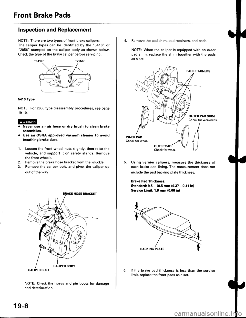
Front Brake Pads
Inspection and Replacement
NOTE: There are two types of front brake calipers:
The caliper types can be identified by the "5410" or"2056" stamped on the caliper body as shown below.
Check the type of the brake caliper before servicing.
5i110 Type:
NOTE: For 2056 type disassembly procedures. see page
19-'10.
Never use an air hose or dry brush lo clean brake
assgmblios.
Use an OSHA approved vacuum cleaner to avoid
breathing brake dust.
Loosen the front wheel nuts slightly, then raise the
vehicle, and support it on safety stands. Remove
the front wheels.
Remove the brake hose bracket from the knuckle.
Remove the caliper bolt, and pivot the caliper up
out of the wav.
1.
2.
NOTE: Check the hoses and pin boots for damage
and deterioration.
CALIPER BOLT
19-8
4. Remove the pad shim. pad retainers, and pads.
NOTE: When the caliper is equipped with an outer
pad shim, replace the shim together with the pads
5. Using vernier calipers, measure the thickness of
each brake pad lining. The measurement does not
include the pad backing plate thickness.
Brake Pad Thickno$:
Standard: 9.5 - 10.5 mm 10.37 - 0.41 in)
SerYico Limit 1.6 mm {0.06 in}
lf the brake pad thickness is less than the service
limit, replace the front Dads as a set.
Page 1163 of 2189
)
It
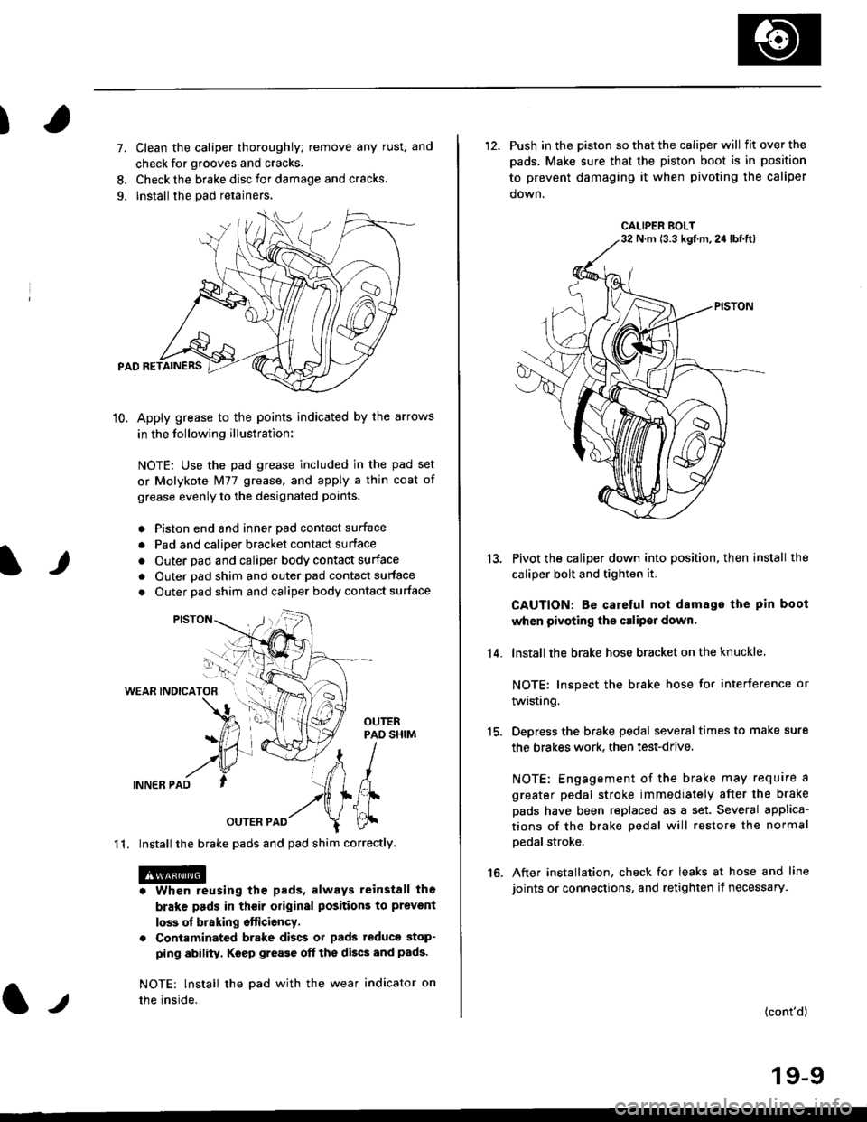
7. Clean the caliper thoroughly; remove any rust, and
check for grooves and cracks.
8. Check the brake disc for damage and cracks.
9. lnstall the pad retainers,
10. Apply grease to the points indicated by the arrows
in the following illustration:
NOTE: Use the pad grease included in the pad set
or Molykote Nl77 grease, and apply a thin coat of
grease evenly to the designated points.
o Piston end and inner Dad contact surface
. Pad and calioer bracket contact surface
. Outer pad and caliper body contact surface
. Outer pad shim and outer pad contact surface
. Outer pad shim and caliper body contact surface
WEAR INDICATOB
INNER PAD
OUTER PAD
1 1. Install the brake pads and pad shim correctly.
. Whon reusing the pads, always reinstall the
brake pads in their original positions to prevont
loss of braking efticiency.
. Contaminated brake discs or pads teduce stop-
ping ability. Keep grease oft the discs and pads'
NOTE: lnstall the Dad with the wear indicator on
the inside.l.t
'12. Push in the piston so that the caliper will fitoverthe
pads, Make sure that the piston boot is in position
to prevent damaging it when pivoting the caliper
down.
Pivot the caliper down into position, then install the
caliper bolt and tighten it.
CAUTION: Be caretul not damage the pin boot
when pivoting the caliper dowr.
lnstall the brake hose bracket on the knuckle
NOTE: Inspect the brake hose for interference or
twisting.
Depress the brake pedal several times to make sure
the brakes work. then test-drive.
NOTE: Engagement of the brake may require a
greater pedal stroke immediately after the brake
pads have been replaced as a set. Several applica-
tions of the brake pedal will restore the normal
Dedal stroke.
After installation. check for leaks at hose and line
joints or connections, and retighten if necessary.
13.
14.
15.
16.
(cont'd)
19-9
CALIPER BOLTN m (3.3 kgf m,2a lbf.ft)
Page 1164 of 2189
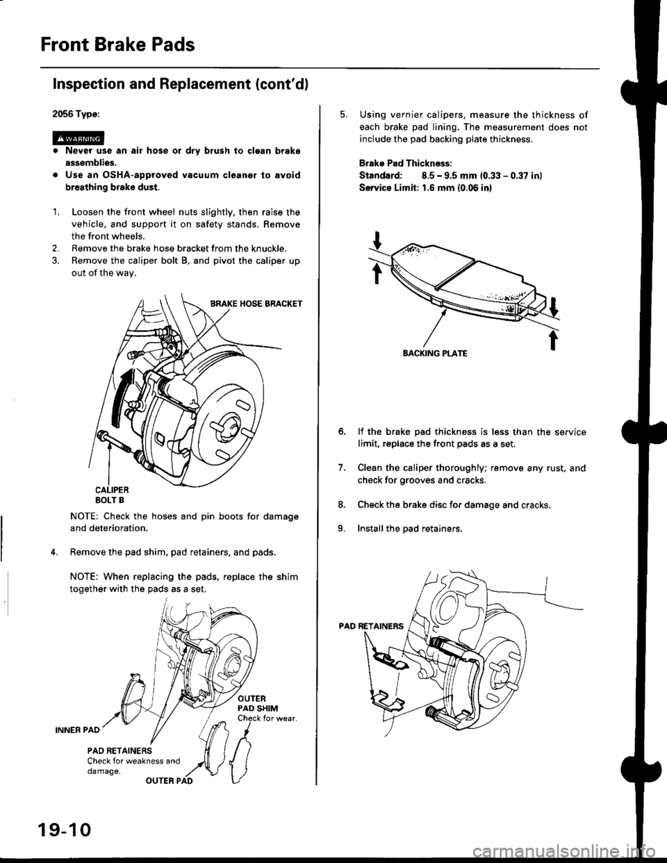
Front Brake Pads
2056 Type:
@. Never use an air hose or dry brush to clgan brake
assemblies.
. Use an OsHA-approved vacuum cleanor lo avoid
breathing broke dust.
Inspection and Replacement (cont'dl
1. Loosen the front wheel nuts slightly. then raise the
vehicle, and support it on safety stands. Remove
the front wheels.
2. Remove the brake hose bracket from the knuckle.
3. Remove the caliper bolt B, and pivot the caliper up
out of the wav,
EOLT B
NOTE: Check the hoses and pin boots for damage
and deterioration.
Remove the pad shim, pad retainers, and pads.
NOTE: When replacing the pads, replac€ the shim
together with the pads as a set,
OUTERPAD SHIMCheck for wear.
INNER PAD
PAO RETAINERSCheck for weakness anddamage,OUTER PAD
19-10
5. Using vernier calipers. measure the thickness of
each brake pad lining. The measurement does not
include the pad backing plate thickness.
Brake Pad Thicknsss:
Standard; 8.5 - 9.5 mm 10.33 - 0.37 in)
Servica Limh: 1.6 mm {0.06 in}
lf the brake pad thickness is less than the service
limit, replace the front pads as a set,
Clean the caliper thoroughly; remove any rust. and
check for grooves and cracks.
Check the brake disc for damage and cracks,
Install the pad retainers.
7.
8.
9.
Page 1165 of 2189
)
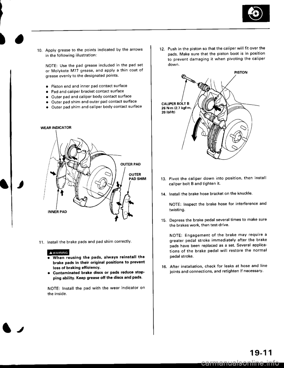
lO. Apply grease to the points indicated by the arrows
in the following illustration:
NOTE: Use the pad grease included in the pad set
or Molykote M77 grease, and apply a thin coat of
grease evenly to the designated points.
. Piston end and inner pad contact surface
o Pad and caliper bracket contact surface
. Outer pad and caliper body contact surface
. Outer pad shim and outer pad contact surface
. Outer pad shim and caliper body contact surface
OUTER PAD
OUIERPAD SHIM
I 1. Install the brake pads and pad shim correctly
@o When reusing the pads, always reinstall the
brake pads in their original positions to plevent
loss of braking etticiencY.
. Contaminated brake discs ol pads reduce stop-
ping ability. Keep grease oft the discs and pads.
NOTE: Install the pad with the wear indicator on
the inside.
WEAR INDICATOR
12. Push in the piston so that the caliper will fit over the
pads. Make sure that the piston boot is in position
to prevent damaging it when pivoting the caliper
CALIPER BOLT B26 N.m {2.7 kgt m,
20 rbl.ftl
14.
13.Pivot the caliper down into position, then install
caliper bolt B and tighten it.
lnstallthe brake hose bracket on the knuckle.
NOTE: Inspect the brake hose for interference and
twisting.
Depress the brake pedal several times to make sure
the brakes work, then test-drive
NOTE: Engagement of the brake may require a
greater pedal stroke immediately after the brake
pads have been replaced as a set. Several applica-
tions ot the brake pedal will restore the normal
pedal stroke.
After installation, check for leaks at hose and line
joints and connections, and retighten if necessary.16.
PISTON
19-1 1