check engine light HONDA CIVIC 1998 6.G Repair Manual
[x] Cancel search | Manufacturer: HONDA, Model Year: 1998, Model line: CIVIC, Model: HONDA CIVIC 1998 6.GPages: 2189, PDF Size: 69.39 MB
Page 1586 of 2189
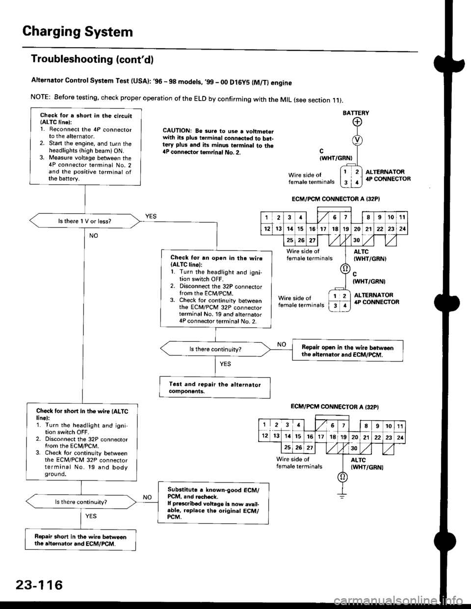
Charging System
Troubleshooting (cont'd)
Alternator Control System Test (USA): ,96 - 98 modets, ,99 _ 00 Dl6y5 (M/Tl engine
NorE: Before testing. check proper operation of the ELD by confirming with the MrL {see section r 1).
BATTERY
CAUTION: Be 3ure to use a voltmot€.with its plus terminal connected to b.t-tery plus and its minus terminal to the{P connectoi tgmrinal No. 2.c
{WHT/GRNt
Wire side oIfemale terminals
ALTERNATOR.P CONNECTOB
Check for a 3hort in the circuitIALTC linel:1. Reconnect the 4P connectorto the alternator,2. Stan the engine, and turn theheadlights {high beam) ON.3. Measure voltage between the4P connector terminal No. 2and the positive terminal ofthe battery.
ls there 1V or less?
Check for rn opon in tha wire(ALTC linol:1. Turn the headlight and igni-tion switch OFF.2. Disconnect the 32P connectortrom the ECM/PCN4.3. Check tor continuity betweenthe ECM/PCM 32P connectorterminal No. 19 and alternator4P connector terminal No. 2.
Bspair open in thg wire lrstweenthe rhern.tor .nd ECM/PCM.
Check for short in the wire (ALTClinel:1. Turn the headlight and ignition switch OFF.2. Disconnect the 32P connectortrom the ECM/PCM.3. Check tor continuity betweenthe ECM/PCM 32P connectorterminal No. 19 and bodyground.
Subslitute a known-good ECM/PCM, .nd .och6ck.It p.escribod vohago i! now avail-able, replace the original ECM/PCM.
Ropair 3hort in the wiro betweonthe ahe.nator and ECM/PCM.
ECM/PCM CONNECTOR A I32PI
'Ia18I1011
121314151718t9
7
202'l2221
262730
Wire side offemale terminalsALTC(WHT/GRNI
c{WHT/GRNI
ALTERNATORWire side oIfemale terminals
([l
T
12
1
ECM/PCM CONNECTOB A (32PI
I23478910t1
1213 14151617182021222321
262730
Wire side of I AITCfemate terminats
A
(WHT/GRN|
23-116
Page 1587 of 2189
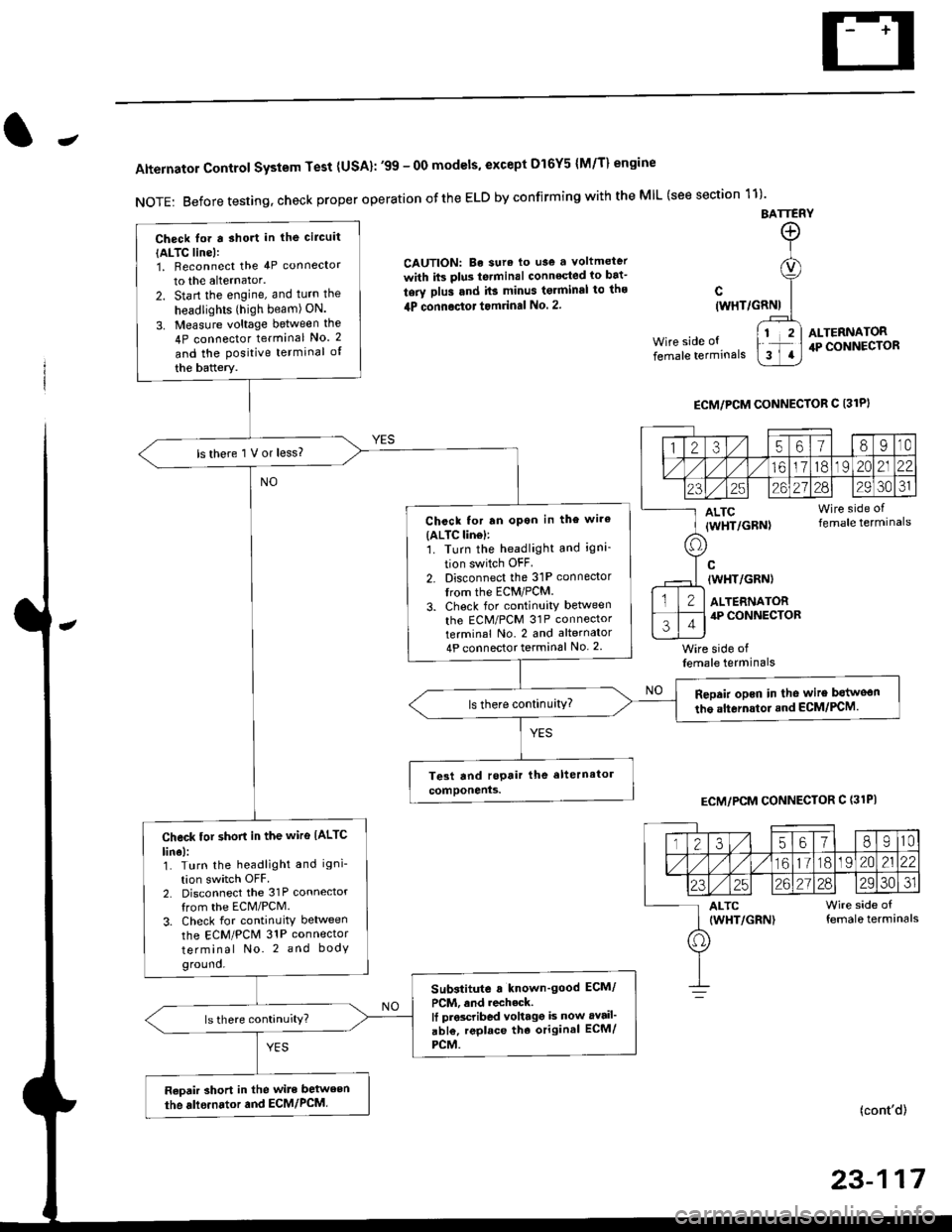
-
Alternator Control System Test {USA}: '99 - 0O models, except Dl6Y5 {M/T} engine
NOTE: Before testing, check proper operation ofthe ELD by confirming with the MIL (see section 11)'
BATTERY
CAUTION: Be sura lo use a voltmeter
with its plus te.minal conneqted io bat-
tery plus and it3 minus tgrminal to ths
4P connoctot tomrinal No. 2.
Wire side of
female terminals
c(WHT/GRNI
wire side offemale terminals
ALTERNATOR.P CONNECTOR
ECM/PCM CONNECTOR C 13lPI
ECM/PCM CONNECTOR C (31PI
(cont'd)
23-117
Check lor a sho.t in the circuit
{ALTC line):1, Beconnect the 4P connector
to the alternator.
2. Start the engine, and turn the
headlights (high beam) ON.
3. Measure voltage between the
4P connector terminal No. 2
and the Positive terminal of
the battery.
ls there 1 V or less?
Chcck for rn opon in the wire(ALTC lin6l:1. Turn the headlight and igni-
tion switch OFF
2. Disconnect the 31P connector
trom the ECM/PCM.
3. Check for continuity betlveen
the ECM/PCM 31P connectorterminal No. 2 and alternator
4P connector terminal No. 2
Repair opcn in the wire botweon
the alternstoi.nd ECM/PCM.ls there continuity?
Check tor short in the wire IALTC
line):1. Turn the headlight and igni-
tion switch OFF2. Disconnect the 31P connector
from the ECM/PCM.
3. Check for continuity between
the ECM/PCM 31P connector
terminal No. 2 and body
ground.
Substitute a known'good ECM/
PCM, and recheck.It prscribed voltagg is now avail'
abl€, replace tho original ECM/
PCM.
Raoair short in the wite between
the alle.nator and ECM/PCM,
1235618I10
/11611lo191 zo2122
23252621?82930JI
ALTC Wire side of(WHT/GRN) female terminals
o
Page 1753 of 2189
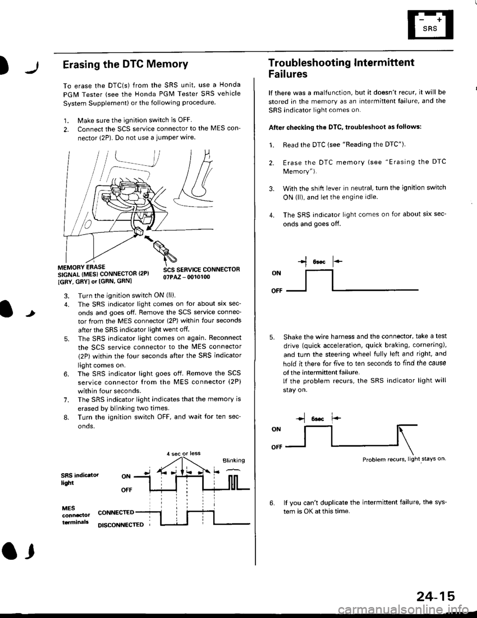
)Erasing the DTC Memory
To erase the DTC(s) from the SRS unit, use a Honda
PGM Tester (see the Honda PGM Tester SRS vehicle
System Supplement) or the following procedure
1. Make sure the ignition switch is OFF
2. Connect the SCS service connector to the MES con-
nector (2P). Do not use a jumper wlre.
]P,
&
.!--J
MEMORY ERASE
SIGNAL (MESI CONNECTOR I2PI
IGRY, GRYI or [GRN, GRNI
SCS SERVICE CONNECTORo?PAZ - 0010100
t
7.
Turn the ignition switch ON (ll).
The SRS indicator light comes on for about six sec-
onds and goes off. Remove the SCS service connec-
tor from the MES connector (2P) within four seconds
after the SRS indicator light went off.
The SRS indicator light comes on again. Reconnect
the SCS service connector to the lvlES connector
(2P) within the four seconds after the SRS indicator
light comes on.
The SRS indicator light goes off. Remove the SCS
service connector from the MES connector (2P)
within four seconds.
The SRS indicator light indicates that the memory is
erased by blinking two times.
Turn the ignition switch OFF, and wait for ten sec-
onos.
8.
SRS indictlorlighi
MESconncclottcaminals
CONNECTED
O,
DISCONI{ECTED
24-15
Troubleshooting Intermittent
Failures
lf there was a malfunction, but it doesn't recur, it will be
stored in the memory as an intermittent failure, and the
SRS indicator light comes on.
Afte. checking the DTC, troubleshoot as lollows:
1. Read rhe DTC {see "Reading the DTC"}.
Erase the DTC memory (see "Erasing the DTC
Memory").
With the shifi lever in neutral, turn the ignition switch
ON (ll), and lei the engine idle.
The SRS indicator light comes on for about six sec-
onds and goes off.
l*F
ON
tl-- -l
Shake the wire harness and the connector, take a test
drive (quick acceleration, quick braking, cornering),
and turn the steering wheel fully left and right, and
hold it there for five lo ten seconds to find the cause
of the intermittent failure.
lf the problem recurs, the SRS indicator light will
stay on.
-q 6a.c f'-
:q
Problem recurs, light stays on
3.
4.
6.lf vou can't duplicate the intermittent failure, the sys-
tem is OK at this time.
Page 1829 of 2189
In the "OHMS" range, the DVOM will measure
resistance between two points along a circuit.
Low resistance means good continuity.
Diodes and solid-state devices in a circuit can
make a DVOM give a false reading. To check
a reading, reverse the leads, and take a
second reading. lf the readings differ, the
component is affecting lhe measurement.
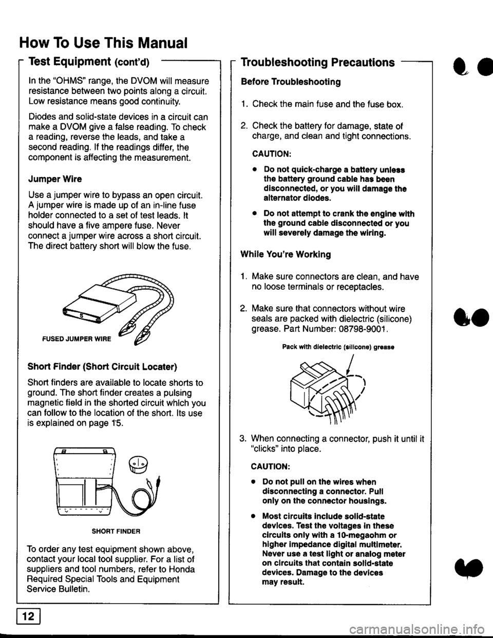
Jumper Wire
Use a jumper wire to bypass an open circuit.
A iumper wire is made up ot an in-line fuse
holder connected to a set of test leads. lt
should have a five amoere fuse. Never
connect a jumper wire across a short circuit.
The direct battery short will blow the fuse.
Short Finder (Short Circuit Locater)
Short finders are available to locale shorts to
ground. The short tinder creates a pulsing
magnetic field in the shorted circuit whlch you
can follow to the location of the short. lts use
is explained on page 15.
SHORT FINDER
To ordei any test equipment shown above,
contact your local tool supplier. For a list of
suppliers and tool numbers, refer to Honda
Required Special Tools and Equipment
Service Bulletin.
How To Use This Manual
Test Equipment (cont'd)
oa
Troubleshooting Precautions
Before Troubleshooting
1. Check the main fuse and the fuse box.
2. Check the battery for damage, state of
charge, and clean and tight connections.
CAUTION:
. Do not quick-charge a battery unlers
the battery ground cable has been
disconnected, or you will damage the
alternator diodes.
. Do not attempt to crank the engine wlth
the ground cable disconnected or you
will severely damage the wiring.
While You're Working
1. Make sure connectors are clean, and have
no loose terminals or receptacles.
2. Make sure lhat connectors without wire
seals are packed with dielectric (silicone)
grease. Part Number: 08798-9001 .
Pack wllh dlelectrlc (sillcons) greass
When connecting a connector, push it until it"clicks" into place.
Do not pull on the wires when
disconnecting a connector. Pull
only on the connector houslngs.
Most circuits Include solid-state
devlces. Test the voltages In these
circuits only with a lo-megaohm or
higher impedance digital multlm6ter.
Never use a test light or analog meter
on chcuits that contain solld-state
devices. Damage to the devices
may result.
oo
Page 1969 of 2189
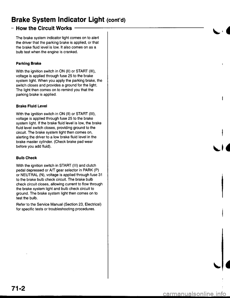
Brake System Indicator Light (cont'd)
- How the Circuit Works
The brake system indicator light comes on to alert
the driver that the parking brake is applied, or that
the brake fluid level is low. lt also comes on as a
bulb test when the engine is cranked.
Parking Brake
With the ignition switch in ON (ll) or START (lll),
voltage is applied through fuse 25 to the brake
system light. When you apply the parking brake, the
switch closes and provides a ground for the light.
The light then comes on to remind you that the
parking brake is applied.
Brake Fluid Level
With the ignition switch in ON (ll) or START (lll),
voltage is applied through fuse 25 to the brake
system light. lf the brake fluid level is low, the brake
fluid level switch closes, providing ground to the
circuit. The brake system light then comes on,
alerting the d verto a low brake fluid level in the
brake master cylinder. (Check brake pad wear
before you add fluid).
Bulb Check
With the ignition switch in START (lll) and clutch
pedal depressed or A'lT gear selector in PARK (P)
or NEUTRAL (N), voltage is applied through fuse 31
to the brake bulb check circuit. The brake bulb
check circuit closes, allowing current to flow through
the brake system light and bulb check circuit to
ground. The brake system light then comes on to
test the bulb.
Refer to the Service Manual (Section 23, Electrical)
for specific tests or troubleshooting procedures.
71-2
a
\fa
Page 2122 of 2189
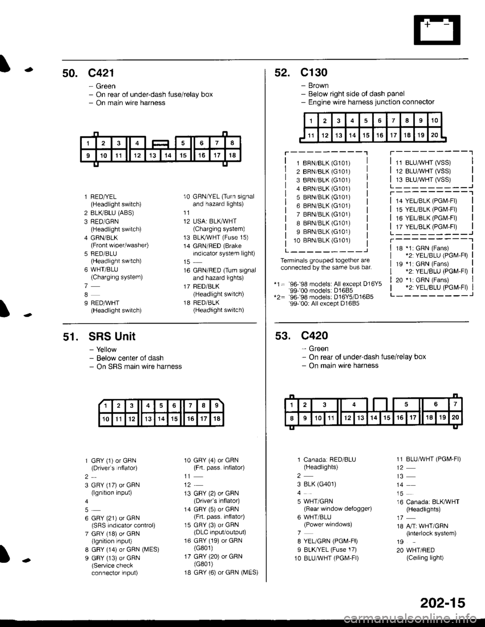
-50. c421
- Green- On rear of under-dash fuse/relay box- On main wire harness
I
l RED/YEL(Headlight switch)
2 BLIVBLU (ABS)
3 RED/GRN(Headlight switch)
4 GFIN/BLK(Front wiper/washer)
5 FED/BLU(Headlight swrtch)
6 WHT/BLU(Charging systern)
7
9 REDAVHT(Headlight switch)
10 GRN/YEL (Turn signaland hazard lights)
11
12 USA: BLKAVHT(Charging system)
13 BLKryVHT (Fuse 15)
14 GRN/RED (Brake
indicator system light)
16 GRN/RED (Turn signaland hazard lights)
17 BED/BLK(Headlight switch)
18 RED/BLK(Headlight switch)
52. C130
- Brown- Below right side ot dash panel- Engine wire harness junction connector
T---------"1
1 8RN/BLK (G101)
2 BRN/BLK (G101)
3 BRN/BLK (G101)
4 BRN/BLK (G101)
5 BRN/BLK (G101)
6 BRN/BLK (G101)
7 BRN/BLK (G101)
I BRN/BLK (G101)
9 BRN/BLK (G101)
10 BBN/BLK (G101)
L---------J
Terminals grouped together areconnected by the sarre bus bar.
*1= 96- 98 models: All except D16Y5'99-'00 models: D1685*2= 96-98 models: D16Y5/D1685'99- 00r All except D1685
11 BLUMHT (VSS)
12 BLU,ryVHT (VSS)
13 BLU,^/VHT (VSS)L_-_____--Jr---------'1
14 YEL/BLK (PGl\4-Fl)
15 YEL/BLK (PGr\4'Fr)
16 YEUBLK (PGI\4,FI)
17 YEUBLK (PGr\4,Fr)L______---JT----------118 *1: GRN (Fans)*2: YEUBLU (PGM-Fl)
19 *1: GRN (Fans).2: YEUBLU (PGM-Fl)
20 *1: GRN (Fans).2: YEUBLU (PGM-Fl)_______--J
51. SRS Unit
- Yellow- Below center oJ dash- On SRS marn wire harness
1 GFY (1) or GRN(Drivefs nflator)
2
3 GRY (17) or GRN(lgn tion input)
6 GRY (21) or GRN(SRS indicalor control)
7 GRY (18) or GRN(lgnition nput)
8 GBY (14) or GRN (MES)
9 GBY (13) of GRN(Service checkconnector input)
10 GRY (4) or GRN(Frt. pass. inflato4
11
13 GBY (2) or GRN(Drivefs nflator)
14 GBY (5) or GRN(Frt. pass. inflator)
15 GRY (3) or GRN(DLC input/output)
16 GRY (19) or GRN(G801)
17 GRY (20) or GRN(G801)
1B GRY (6) or GRN (MES)
13678
10Il12131415't7't8
53. C420
- Green- On rear of under-dash fuse/relay box- On main wire harness
1 Canadar RED/BLU(Headlights)
2
3 8LK (G401)
5 WHT/GRN(Rear window defogger)
6 WHT/BLU(Power windows)
7
8 YEL/GRN (PGM-FD
I BLK//EL (Fuse 17)
1O BLUAVHT (PGM,FI)
1 1 BLUMHT (PGI,4-FI)
14
16 Canada: BLKAVHT(Headlights)
18 A/Tr WHT/GRN(lnterlock system)
19
20 WHT/RED(Ceiling light)
202-15