Atf HONDA CIVIC 1998 6.G Manual Online
[x] Cancel search | Manufacturer: HONDA, Model Year: 1998, Model line: CIVIC, Model: HONDA CIVIC 1998 6.GPages: 2189, PDF Size: 69.39 MB
Page 990 of 2189
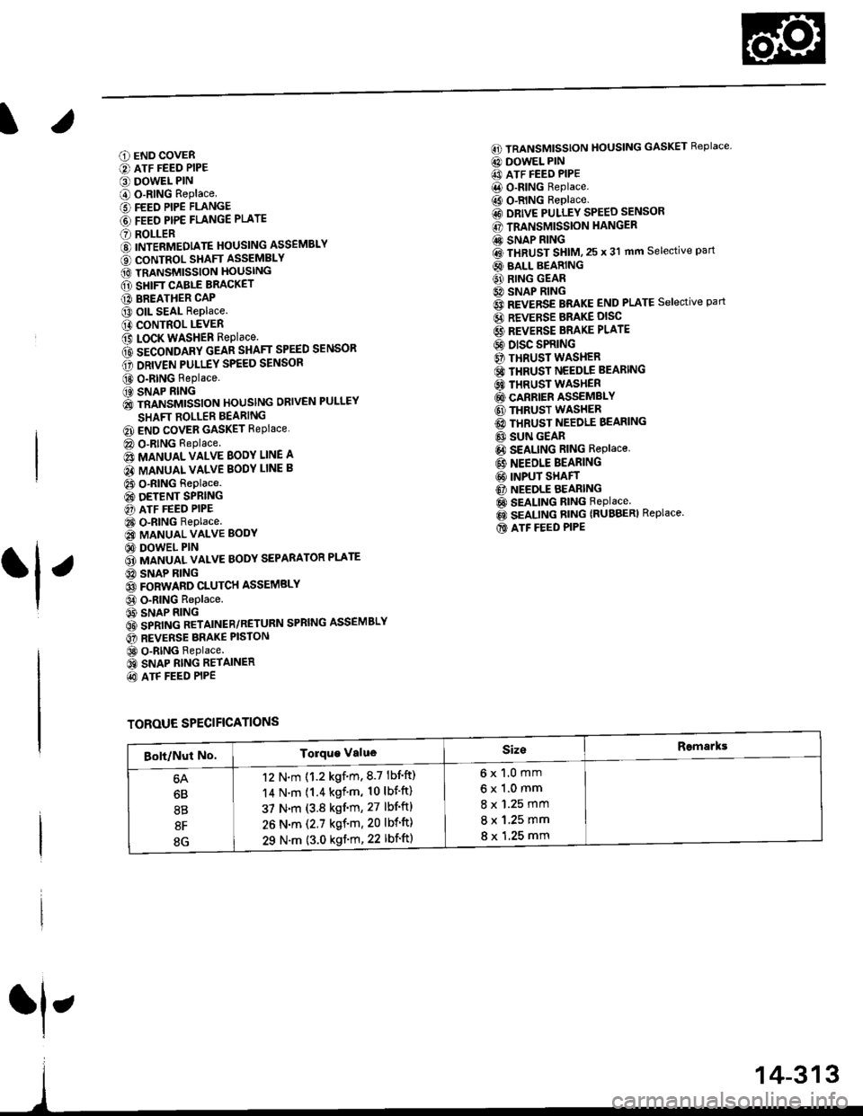
6) TRANSMISSION HOUSING GASKET Replace'
@ DOWEL PIN
@) ATF FEED PIPE
@ o-RING Replace.
60 o-RING Replace.
@) DRIVE PULLEY SPEED SENSOR
@ TRANSMISSION HANGER
@ SNAP RING
@ txaust Sxtfu, zs t 31 mm selective part
@ SALL BEARING
6J RING GEAR6D SNAP RING
@ aevense aRlxe rND PLATE Selective part
@ REVERSE BRAKE DISC
@ REVERSE BRAKE PLATE
@ DISC SPRING6} THNUST WASHER
@} finusr NeeoLr eelnNc
@ THRUST WASHER
@ GARRIER ASSEMBLY
@ THRUST WASHER
@ THRUST NEEDLE BEARING
@} SUN GEAR
@ SEALING RING REPIACE'
@ NEEDLE BEARING
@ INPUT SHAFT
@ NEEDLE BEARING
@ SEALING RING FEPIACE'
@ SEALING RING {RUBBERI Replace'
@ ATF FEED PIPE
O END COVER
O ATF FEED PIPE
O DOWEL PIN
@ O-RING Replace.G) FEED PIPE FLANGE
@ reeo ppe ruruce puru
O] ROLLERO IruTENMEDNTE XOUSING ASSEMBLY
ao corutnoL sxlrr lsseugLv
@ tnlrusmtsstottt ttoustt'tc
@ SHIFT CABLE BRACKET
c) BREATHER CAP
@ oll- SEAL Replace.
@ CONTROL LEVER
G LoCK WASHER Replace.(D secololaY ceaR SHAFT SPEED sENsoR
o) onvel put-uv sPEED SENSOR
@ O-RING Replace.(O SNAP RING6 rnmrsutsstoru xouslNc oRlvEN PULLEY
SHAFT ROLLER BEARING
@ END COVER GASKET REPIACE'
@ o-RING Replace
6o mnruulL vnLVe goDY LINE A
64 MANUAL VALVE BODY LINE B
@ O-RING Replace.
@ DETENT SPRING
O ATF FEED PIPE
@ O-RING Replace.
@ MANUAL VALVE EODY
@ DOWEL PIN
@ r'rllull valve goDY SEPARAToR PLATE
6D SNAP RING
@t roRwlno cturcx ASSEMBLY
@ o-RING Replace
@ SNAP RINGo3 spnlruc aetlrupn/RETURN SPRING ASSEMBLY
@ nevense ennr eBtottt
@ o-RING Feplace.
@ SNAP RING RE'AINER
@ ATF FEED PIPE
.1,
TOROUE SPECIFICATIONS
6x1.0mm
6x1.0mm
8 x 1.25 mm
8 x 1.25 mm
8 x 1.25 mm
12 N.m (1.2 kgf'm,8.7 lbf'ft)
14 N.m {1.4 kgf'm, 10 lbift)
37 N.m (3.8 kgf'm, 27 lbf'ft)
26 N.m (2.7 kgf'm,20 lbf'ft)
29 N.m (3.0 kgf'm, 22 lbf'ft)
6B
8B
8F
8G
14-313
rl,
Page 991 of 2189
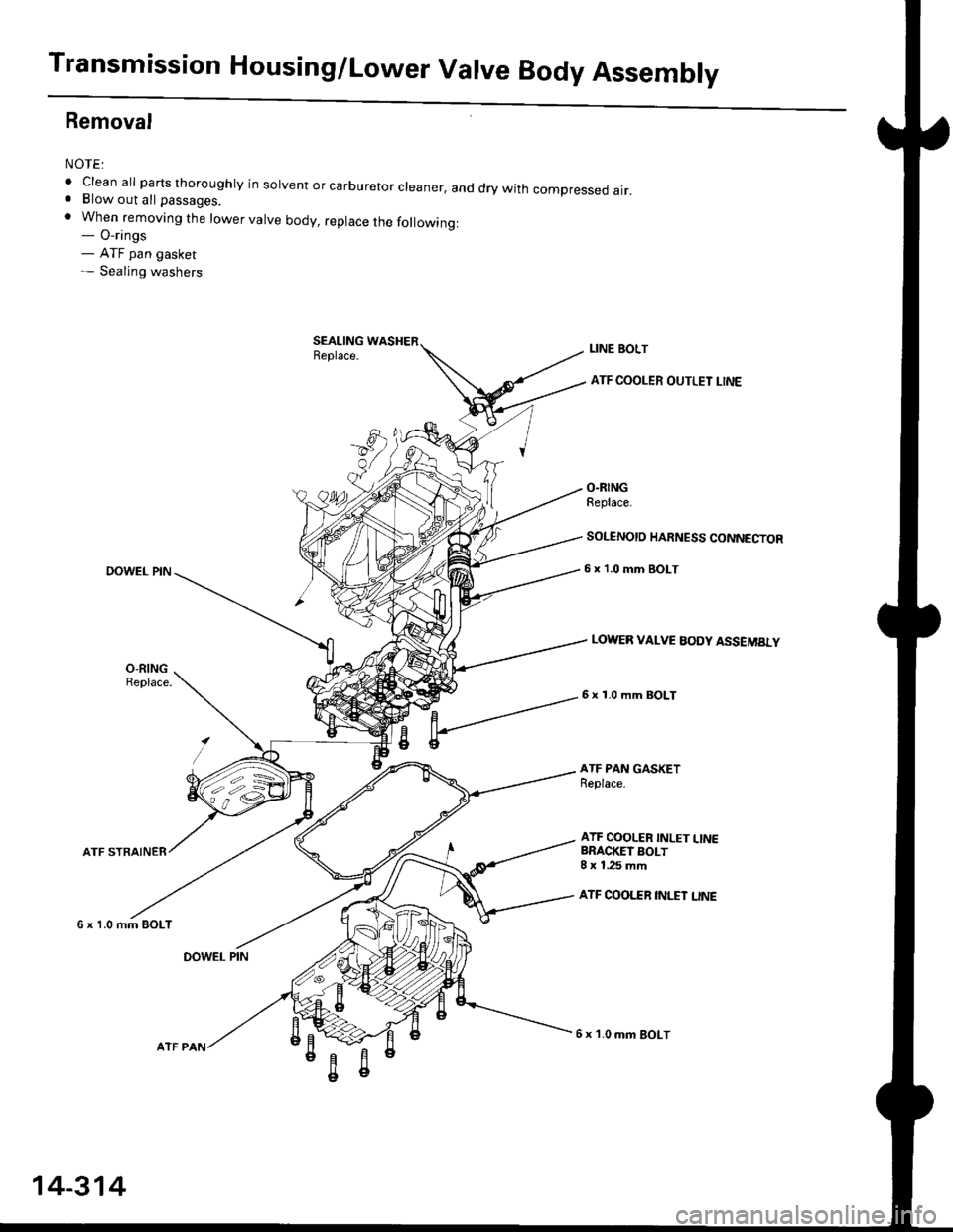
Transmission Housing/Lower Valve Body Assembty
Removal
NOTE:
. Clean all parts thoroughly in solvent or carburetor cleaner, and dry with compressed air.. Blow out all passages.
. When removing the lower valve body, replace the followingl- O-rings- ATF pan gasket- Sealing washers
DOWEL PIN
ATF STRAINER
6 x 1.0 mm BOLT
ATF PAN GASKETReplace.
ATF COOLER INLET LINEBRACKET BOLT8 x 1.25 mm
ATF COOI..ER INLET LINE
O.RINGReplace.
SOLENOIO HARNESS CONNECTOR
6 x'1.0 mm BOLT
LOWER VALVE BODY ASSEMBLY
6 x 1.0 mm BOLT
14-314
6 x 1.0 mm EOLT
Page 992 of 2189
l.
'1.
2.
5.
6.
7.
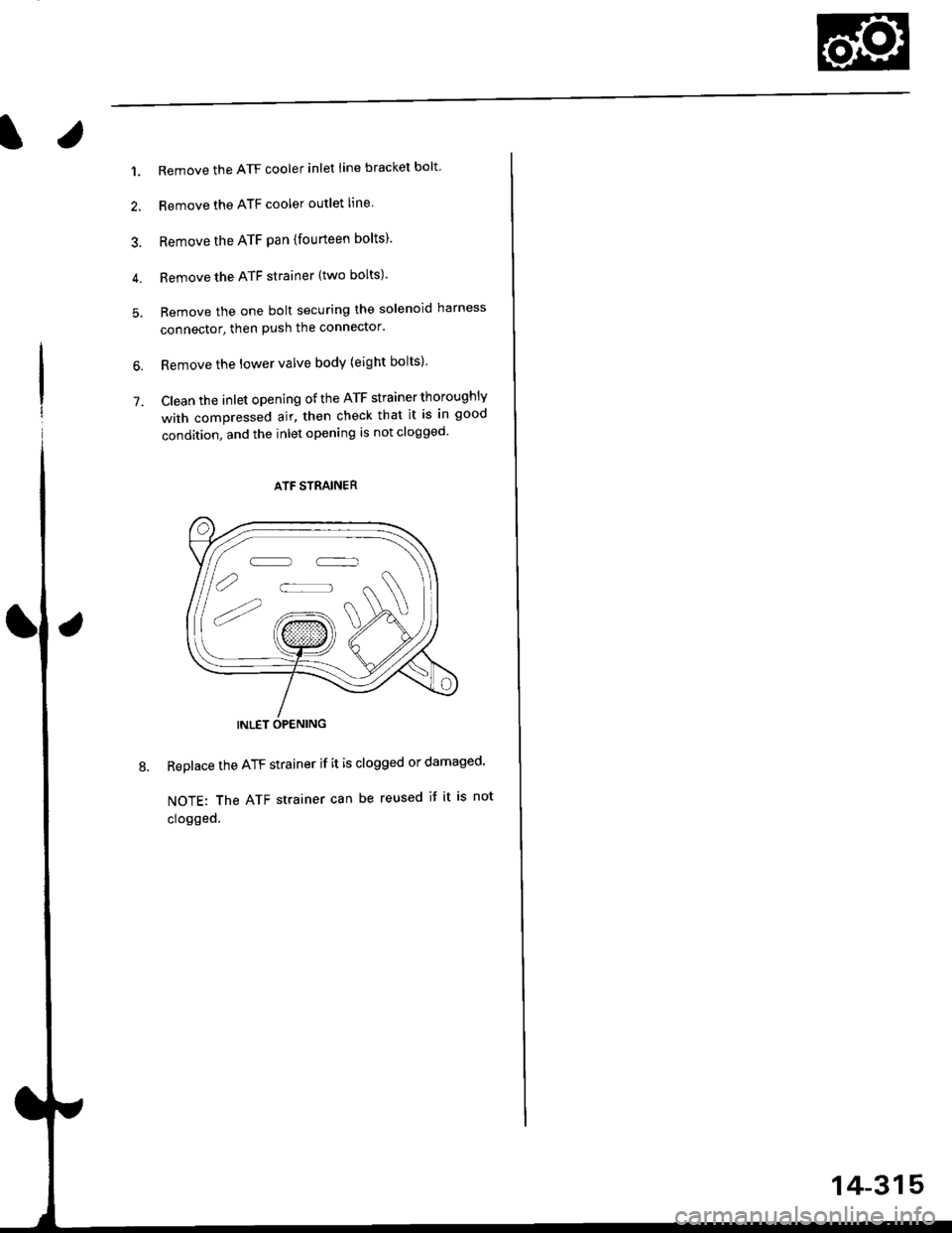
Remove the ATF cooler inlet iine bracket bolt'
Remove the ATF cooler outlet line
Remove the ATF pan (fourteen bolts).
Remove the ATF strainer {two bolts)
Remove the one bolt securing the solenoid harness
connector, then push the connector.
Remove the lower valve body (eight bolts)
Clean the inlet opening of the ATF strainer thoroughly
with compressed air, then check that it is in good
condition, and the inlet opening is not clogged'
ATF STRAINER
INLET OPENING
Replace the ATF strainer if it is clogged or damaged
NOTE: The ATF strainer can be reused it it is not
clogged.
2c'
c;2 ar\
14-315
Page 993 of 2189
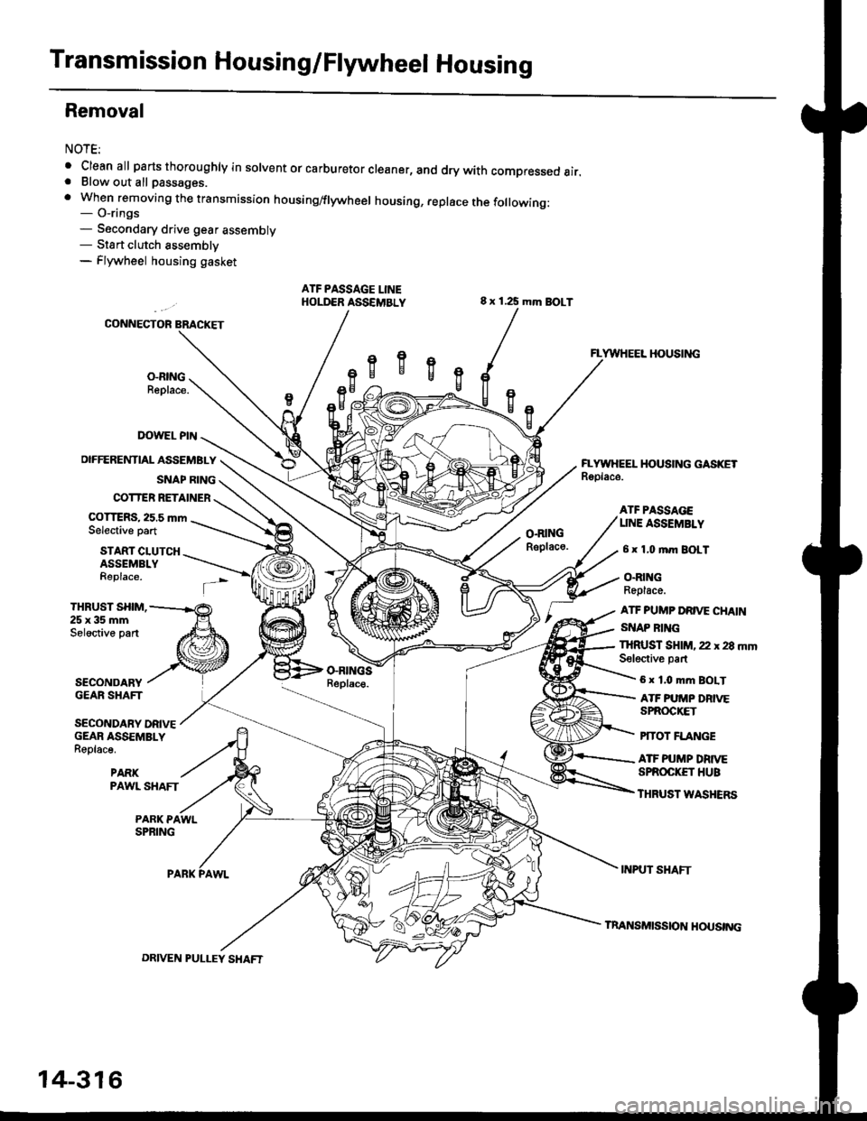
Transmission Housing/Flywheel Housing
Removal
NOTE:
. Cleanall parts thoroughly in solvent or carburetor cleaner, and dry with compressed air.. Blow out all passages.
. When removing the transmission housing/flywheel housing, replace the following:- O-rings- Secondary drive gear assembly- Sta rt clutch assemblv- Flywheel housing gasket
ATF PASSAGE LINEHOLD€R ASSEMBLY
IX)WEL PIN
OIFFERENTIAL ASSEMBLY
SNAP RING
COTTER RETAINER
COTTERS, 25.5 mmSelective part
8 x 125 mm BOLT
O.RINGRsplaco.
VWHEEL HOUSING
EYWIIEEL HOUSING GASKETRoolace.
START CLUTCHASSEMBLYReplace.
ATF PA$gAGEUNE ASSEMBLY
6 x 1,0 mm BOLT
O.RINGReplace.
ATF PUMP DRIVE CHAIN
SNAP RING
THRUST SHIM,25x35mmSeloctive part
SECONDARYGEAR SHAFT
SECONDARY DRIVEGEAR ASSEMBLYReplace.
PARKPAWL SHAFT
THRUST SHIM, 22 r 28 mmSeloctive partGRII{GSReplac€.6 x 1.0 mm BOIT
ATF PUMP DRIVESPROCKET
PfTOT FLANGE
ATF PUMP DRTVESPROC|(ET HUB
THRUST WASHERS
PARK PAWLSPRING
INPUT SHAFT
14-316
DRIVEN PULLEY SHAFT
InANSMISS|O]{ HOUSTNG
Page 994 of 2189
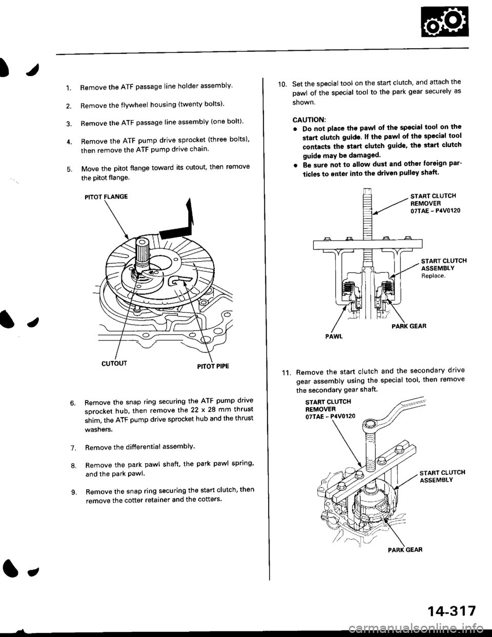
)
1.Remove the ATF passage line holder assembly'
Remove the flywheel housing (twenty bolts)'
Remove the ATF passage line assembly (one bolt)
Remove the ATF pump drive sprocket (three bolts),
then remove the ATF pump drive chaan.
Move the pitot flange toward its cutout, then remove
the pitot flange.
PITOT PIPE
Remove the snap ring securing the ATF pump drlve
sprocket hub. then remove the 22 x 28 mm thrust
shim, the ATF pump drive sprocket hub and the thrust
wasners,
Remove the differential assemblY.
Remove the park pawl shaft, the park pawl spring,
and the park Pawl'
Remove the snap ring securing the start clutch, then
remove the cotter retainer and the cotters.
7.
9.
J
14-317
10. Set the special tool on the start clutch' and attach the
oawl of the special tool to the park gear securely as
shown.
CAUTION:
. Do not place tho pawl of the spocial tool on the
start clutch guidc. ll the pawl ot the spocial tool
contacts the 3tart clutch guid€, the start clutch
guido may be damaged.
. Be sure not to allow dust and other foreign par-
ticles to enter into the drivon pull6y shaft'
START CLUTCHREMOVER07TAE - P4V0120
11.Remove the start clutch and the secondary drive
gear assembly using the special tool, then remove
the secondary gear shaft.
START CLUTCHREMOVER07TAE - P4V0120
START CLUTCHASSEMBLYReplace.
START CLUTCHASSEMBLY
PAWL
Page 1014 of 2189
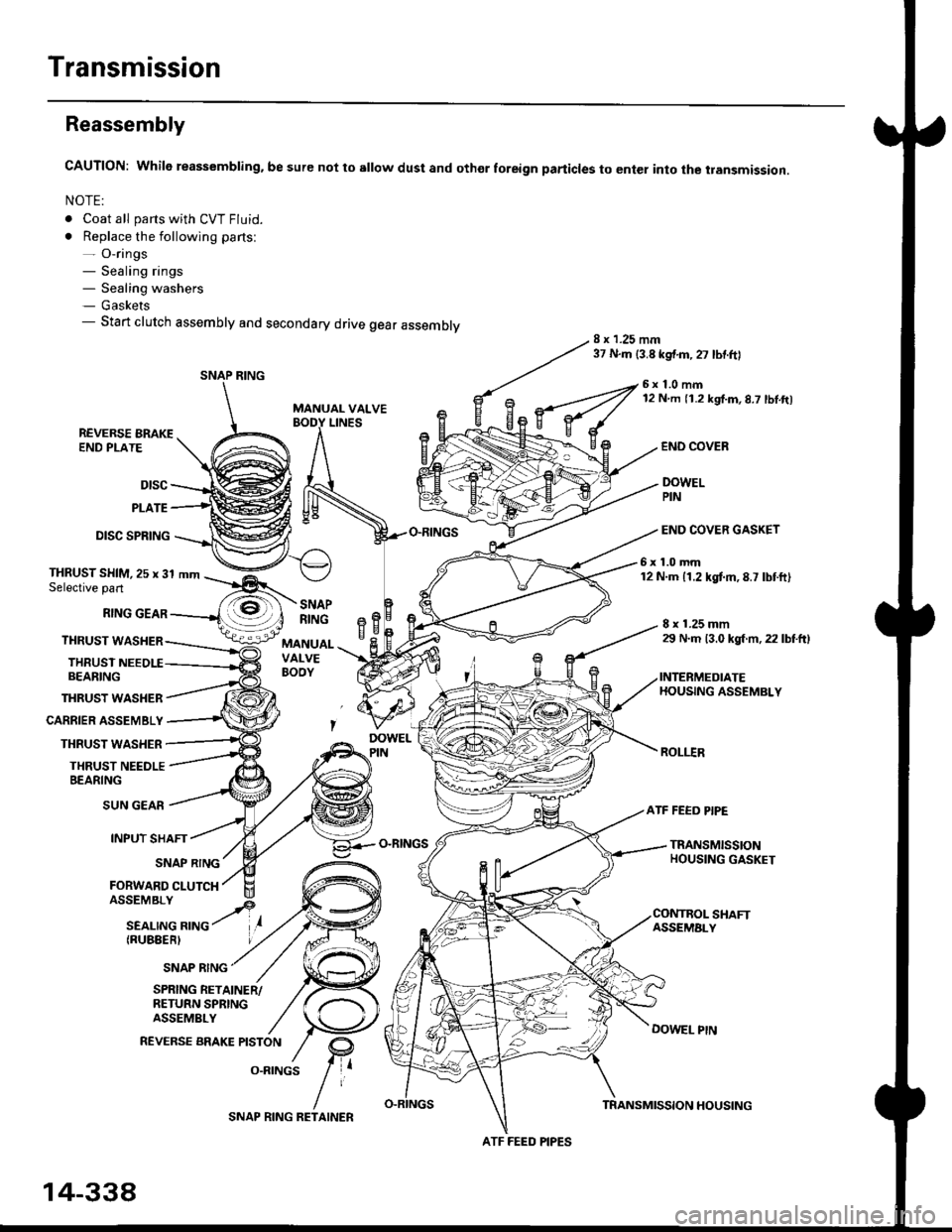
Transmission
Reassembly
CAUTION: While reassembling. be sure not to sllow dust and othor foreign particles to enter into the transmission.
NOTE:
. Coat all parts with CVT Fluid.
. Replace the following parts:- O-rings- Sealing rings- Sealing washers- Gaskets- Start clutch assembly and secondary drive gear assembly8 x 1.25 mm37 N.m {3.8 kgf.m,27 lbtftl
MANUAL VALVE
6x1.0mm12 N m 11.2 kgf.m,8.7 lbl.ft)
LINESREVERSE BRAKEEND PLATE
Dtsc
PLATE
DISC SPRING
THRUST WASHER
CARRIER ASSEMBLY
THRUST WASHER
THRUST NEEDLEBEARING
END COVEB
DOWELPIN
END COVER GASKET
6x1.0mm12 N.m 11.2 kgtm,8.7 lbtft)THRUST SHIM,25 x 31 mmSelective part
RING GEAR
THRUST WASHER
THRUSTBEARING
8 x 1.25 mm29 N.m 13.0 kgl m, 22 lbtftl
INTERMEDIATEHOUSING ASSEMBLY
ROLI.IR
SNAPRINGeBH^cMANUALVALVEBOOY
SUN GEAR
INPUT SHAFT
(RUBEERI
ATF FEED PIPE
O-RINGSTRANSMISSIONHOUSING GASKETSNAP RING
FORWARD CLUTCH
SNAP RING
SHAFTASSEMALY
DOWEL PtN
SPRING RETAINER/RETURN SPRINGASSEMBLY
REVERSE BRAKE PISTON
O.RINGS
SNAP RING
ATF FEED PIPES
14-338
SNAP RING RETAINERTRANSMISSION HOUSING
Page 1015 of 2189
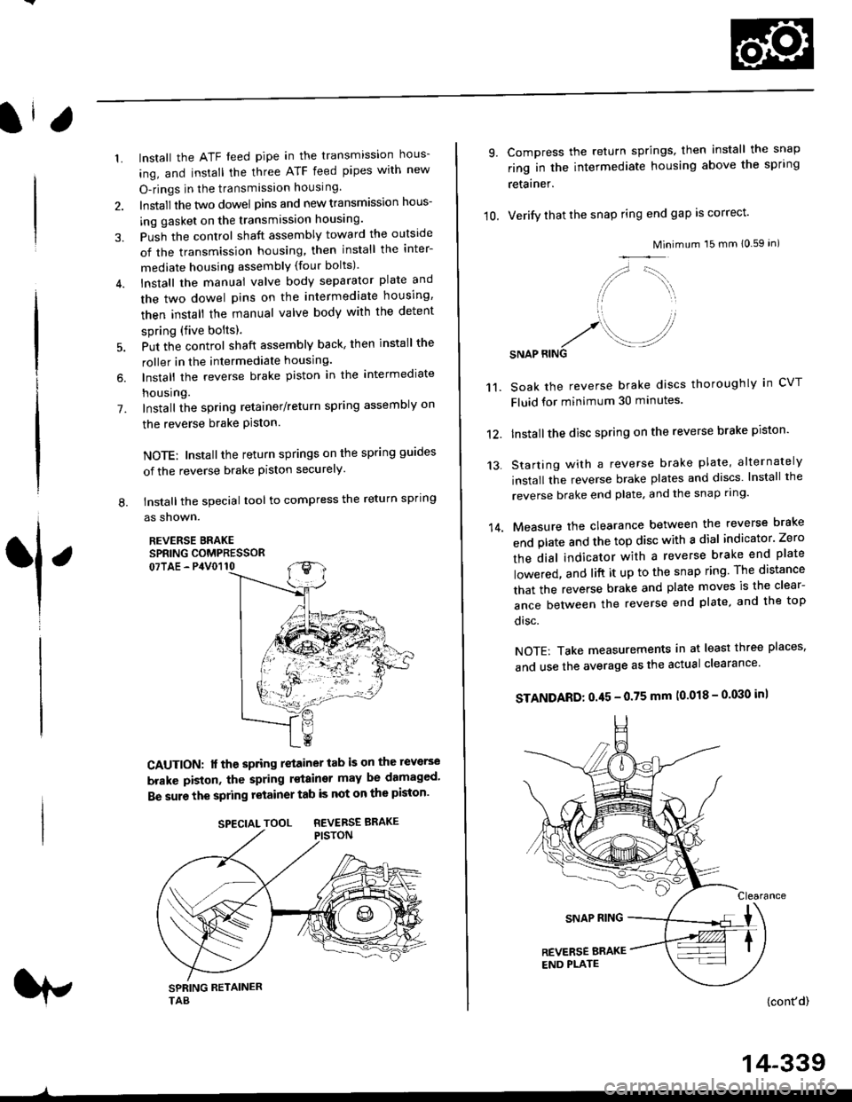
1.
7.
lnstall the ATF feed pipe in the transmission hous-
ing, and install the three ATF feed pipes with new
O-rings in the transmission housing,
Install the two dowel pins and new transmission hous-
ing gasket on the transmission housing.
Push the control shaft assembly toward the outside
of the transmission housing, then install the inter-
mediate housing assembly (four bolts).
lnstall the manual valve body separator plate and
the two dowel pins on the intermediate housing,
then install the rnanual valve body with the detent
spring (five bolts).
Put the control shaft assembly back, then install the
roller in the intermediate housing.
lnstall the reverse brake piston in the intermediate
housing.
Install the spring retainer/return spring assembly on
the reverse brake Piston.
NOTE: Installthe return springs on the spring guides
of the reverse brake piston securely
tnstall the special tool to compress the return spring
as shown.
REVERSE BRAKESPRING COMPRESSOR07TAE - P4V0110
6.
L
1
CAUTION: lf the spring retainer tab is on the reverse
brakc piston, the spring rstainer may be damaged'
Be sure the spring retainer tab is not on the piston'
rp
SPECIALTOOL REVERSEBRAKE
-^
14-339
10.
9.
14.
Compress the return springs, then install the snap
ring in the intermediate housing above the spring
retainer.
Verify that the snap ring end gap is correct'
Mini
/,,- '-t,,,,.
// \i/ ',r
'1 ,
.r' //'/. .-J?RINGSNAP
mum 15 mm 10.59 in)
Soak the reverse brake discs thoroughly in CVT
Fluid for minimum 30 minutes.
Installthe disc spring on the reverse brake piston'
Starting with a reverse brake plate, alternately
install the reverse brake plates and discs lnstall the
reverse brake end plate, and the snap ring'
Measure the clearance between the reverse brake
end plate and the top disc with a dial indicator' Zero
the dial indicator with a reverse brake end plate
lowered, and lift it up to the snap ring The distance
that the reverse brake and plate moves is the clear-
ance between the reverse end plate, and the top
disc.
NOTE: Take measurements in at least three places'
and use the average as the actual clearance'
STANDARD: 0.45 - 0.75 mm (0.018 - 0'030 in)
{cont'd)
11.
12.
13.
Page 1018 of 2189
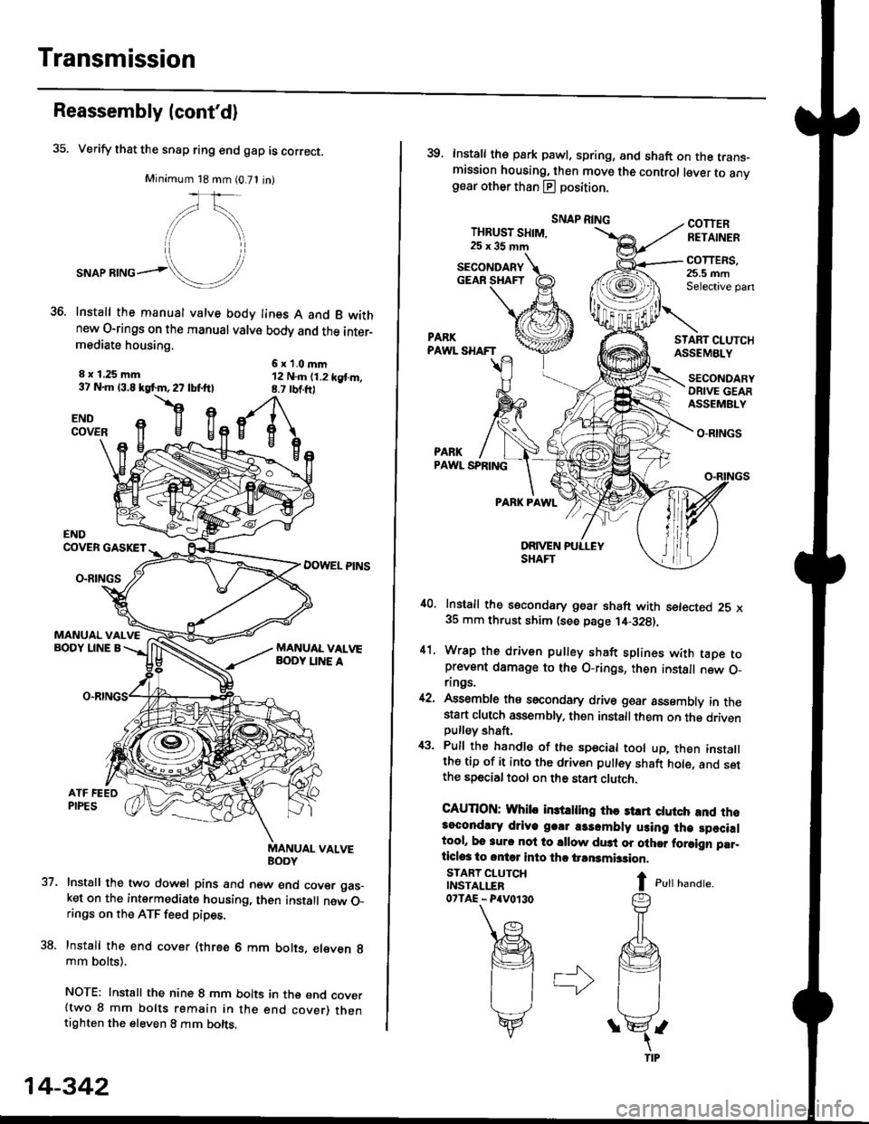
Transmission
Reassembly (cont'd)
35. Verify that the snap ring end gap is correct.
Minimum 18 mm (0.71 in)
,/\,
."or**ol!/'
Install the manual valve body lines A and B wkhnew O-rings on the manual valve body and the inter-mediate housing.
6x1.0mm12 N..n (1.2 kgt m,8.7 rbtft)
8 x 1.25 mm37 N.m 13.8 kgf.m,27 lbf.ftl
flgENDCOVER
37.
ENDCOVER GASKET
DOWEL PINSO-RINGS
MANUAL VALVEBODY LINE A
uaNYuAL VALVE
Install the two dowel pins and new end cover gas_ket on the intermediate housing, then install new O_rings on the ATF feed pipes.
Install the end cover (three 6 mm bolts, eleven g
mm bolts).
NOTE: Install the nine 8 mm bolts in the end cover(two 8 mm bolts remain in the end cover) thentighten the eleven 8 mm bolts.
14-342
39. Install the park pawl, spring, and shaft on the trans-mission housing, then move the control lever to anvgear other than E position.
THBUST SHIM,25x35mm
SNAP RINGCOTTERRETAINER
COTTERS,25.5 mmSelective pan
START CI.UTCHASSEMBLY
O.RINGS
PARKPAWL SPRING
PARK PAWL
,10, Install the secondary gear shaft with setected 25 x35 mm thrust shim (see page ,14-328).
41. Wrap the driven pulley shaft splines with taDe toprevent damage to the O-rings, then install new O_rings.
42, Assemble ths secondary drive goar assembly in thestart clutch assembly, then installthem on the drivenpulley shaft,
43. Pull the handle of the special tool up, then installthe tip of it into the driven pulley shaft hole, and setthe special tool on the stan clutch.
CAUTION: Whib in3trling thc st rt ctutch and rh.3ocondlry driye g.!r a3sombly using lh€ specialtool, bo 3urc nol to sllow du3t or olher foraign par_ticlos to ontq into tho iransmbsion.
I c,rr r,unar".
SECONDARYGEAR SHAFT
START CLUTCHINSTALLER07TAE - P4V0r30
SECONDARYORIVE GEAFASSEMBLY
Page 1019 of 2189
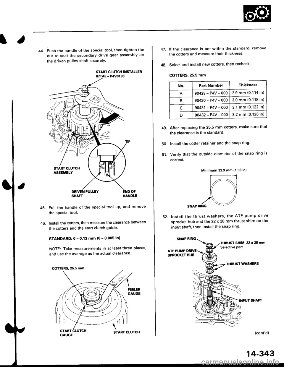
44. Push the handle of the special tool, then tighten the
nut to seal the secondary drive gear assembly on
the driven pulleY shaft securelY.
STAAT CLUTCH Ii'ISTALIIR07TAE - PaV0130
OF
46.
SHAFTHA'{DI,-E
Pull the handle of the special tool up, and remove
the special tool.
lnstallthe cotters, then measure the clearance Delween
the cotters and the start clutch guide
STANDARD: 0 - 0.13 mm (0 - 0.005 inl
NOTE: Take measurements in at least three places,
and use the average as the actual clearance
GAUGE
lil(il
COTTERS, 25.5 mm
START 1
GAUGCSTART CLUTCH
14-343
47.
48.
lf the clearance is not within the standard, remove
the cotters and measure their thickness
Select and install new cotters, then recheck.
COTTERS, 25.5 mm
After replacing the 25.5 mm cotters, make sure that
the clearance is the standard
lnstall the cotter retainer and the snap rlng
Verify that the outside diameter of the snap ring is
correct.
Minimum 33.9 mm (1.33 in)
SNAP RII{G
lnstall the thrust washers. the ATF pump drrve
sprocket hub and the 22 x 28 mm thrust shim on the
inDUt shaft, then install the snap ring.
49.
50.
52.
THRUST WASXERS
INPUT SHAFT
(cont'd)
No.Part NumberThickness
90429-P4V-0002.9mm(0.114 in)
B90430-P4V-0003.0mm(0.118 in)
c90431 -P4V-0003.1 mm (0.122 ln)
D90432-P4V-0003.2 mm (0.126 in)
SNAPRING\
ATF PUMP DRIVESPROCKET HUB
THFUST SHIM, 22 x 2a mm
Selective pan
Page 1020 of 2189
Transmission
Reassembly (cont'd)
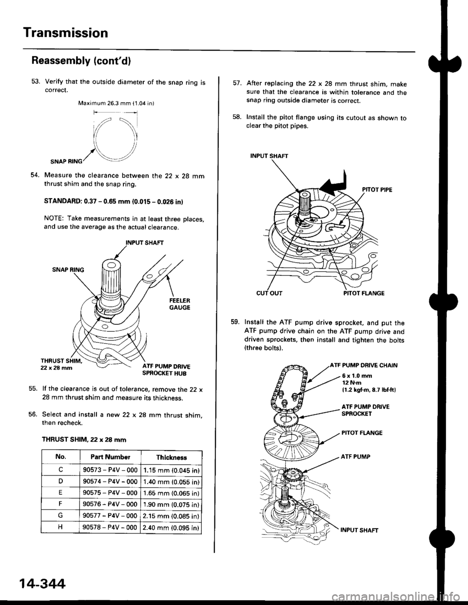
53. Verify that the outside diameter of the snap ring iscorrect.
Maximum 26.3 mm (1.04 in)
54.
SNAP RING
Measure the clearance between the 22 x 28 mmthrust shim and the snap ring.
STANDARD: 0.37 - 0.65 mm (0.015 - 0.026 inl
NOTE: Take measurements in at least three places,
and use the average as the actual clearance.
lf the clearance is out of tolerance, remove the 22 x
28 mm thrust shim and measure its thickness.
Select and install a new 22 x 28 mm thrust shim,then recheck.
THRUST SHIM, 22 x 28 mm
55.
co.
No.Part Numb€rThicknsss
c90573-P4V-0001.15 mm (0.0,{5 in)
D90574-P4V-0001.40 mm {0.055 in)
E90575-P4V-0001.65 mm (0.065 in)
F90576-P4V-0001.90 mm (0.075 in)
90577-P4V-0002.15 mm (0.085 in)
90578-P4V-0002.40 mm (0.095 in)
14-344
INPUT SXAFT
After replacing the 22 x 28 mm thrust shim. makesure that the clearance is within tolerance and thesnap ring outside diameter is correcr.
Install the pitot flange using its cutout as shown toclear the pitot pipes.
Install the ATF pump drive sprocket. and put theATF pump drive chain on the ATF pump drive anddriven sprockets, then install 8nd tighten the bolts(three bolts).
TF PUMP DRIVE CHAIN
58.
59.
6x1.0mm12 N.m
11.2 kg{.m,8.7 lbf.ftl
ATF PUMP ORIVESPROCKET
PITOT FLANGE
ATF PUMP