Model HONDA CIVIC 1998 6.G Manual Online
[x] Cancel search | Manufacturer: HONDA, Model Year: 1998, Model line: CIVIC, Model: HONDA CIVIC 1998 6.GPages: 2189, PDF Size: 69.39 MB
Page 319 of 2189
System Description
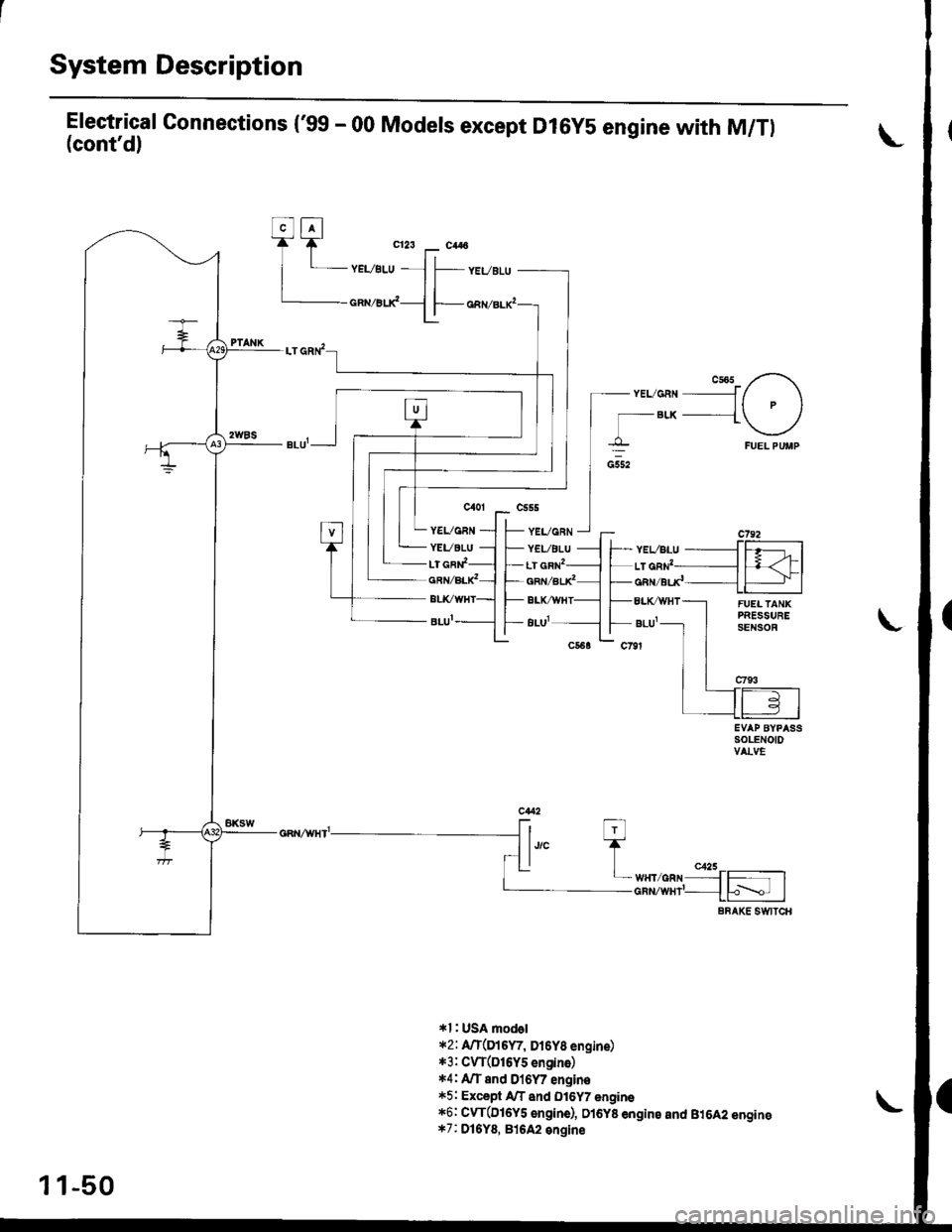
Electrical Connections ('gg - 00 Models except Dl6y5 engine with M/Tl(cont'd)
CsO5 -r-\- YELI6RN f/ \It P I
'- BLK __1 /
I \'----l
Ft,EL PUMP
EVAP BYPASSSOLENOIDVALVE
ft ti-l
I lJ/c TT__l It.] I c425 __
I LwHr GRN {-l_cnnzwm'_{h\_, IaBAKE StlflTCB
*l : USA mod6l*2: A/T(Di6W, Dt6Y8 engine)*3: CW(DI6Y5 engino)*4: A,rT e16 915y7 "nn,n"*5: ExceB AfT and Dl6Y7 engine,16: Cyr(DI6Y5 €n9ine), D16y8 engine and B,tOA2 engins*7: Dl5Y8, 816A2 engine
Elt^-l'tF'tF q23 r_ c446
I L vever-u - l l-- ,.,- ,.u
t|lL-- cnrzer-rc-{f cnnzar-x,
YEL/GRN
YEVELU
- YEL/GRN- YEVBLU
lr cat'�_ LT GRN2qar/auC- qaN/eud
BLVWHf- BLK/WiT
BLIII- BLul
1 1-50
Page 320 of 2189
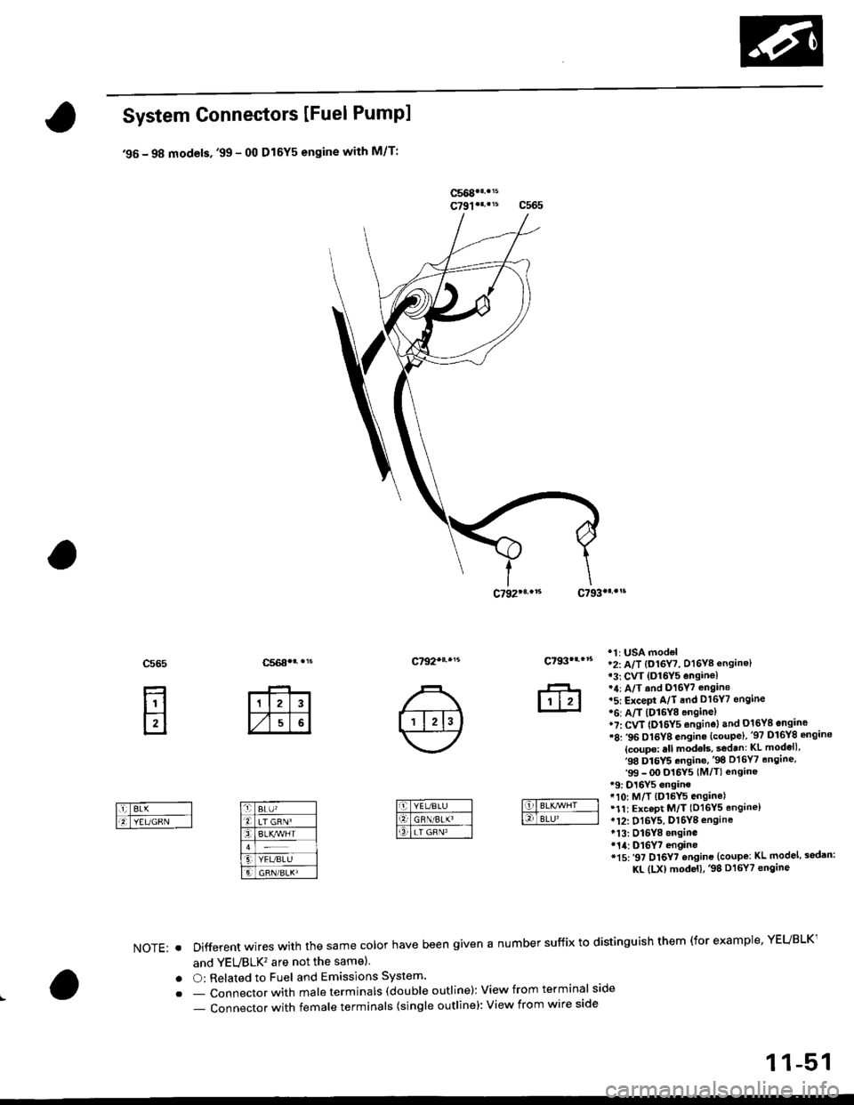
System Connectors [Fuel Pumpl
'95 - 98 models, '99 - 00 Dl6Y5 engine with M/T:
ffi
c565
E
c792*r,.'5c793|.,.s
*1r USA mod€l'2: A/T {O16Y7, D16Y8 ensine}13: CVT {O16Y5 ensin€l*4: A/T ind D16Y7 .ngane*5: ExceFt A/T end D16Y7 engine'6: A/T lDl6Y8 enginel*7: CvT (Dl6Y5 enginoland 016Yg engine'8: ,96 Dl6YB engine {coupe),'97 Dl6Y8 sngine
{coupe: sll models, s€d.nr KL modell,'98 Dl5Y5.ngine,'98 D16Y7 engine,'99 - OO Dl6Y5 (M/Tl enginer9: D16Y5 onginet10: M/T {D15Y5 ensinelr1t: ExceDt M/T (D16Y5 engine)tl2: D16Y5, Dl6Yg engine*13: Dl6Y8 enginer14: D16Y7 engine*15:'97 Dl6Y7 ensine {coupe: KL model, sodan:
KL (LX) modeu,'98 Dt6Y7 engine
NOTE: . Different wires with the same color have been given a number suffix to distinguish them (for example' YEUBLK1
and YEVBLK'� are not the samel.
. O: Related to Fuel and Emissions System'
. - Connector with male terminals (dou ble outline): View f rom term inal side
- Connector with female terminals (single outline): View from wire side
c7931...15
ffi
1 1-51
Page 331 of 2189
System Description
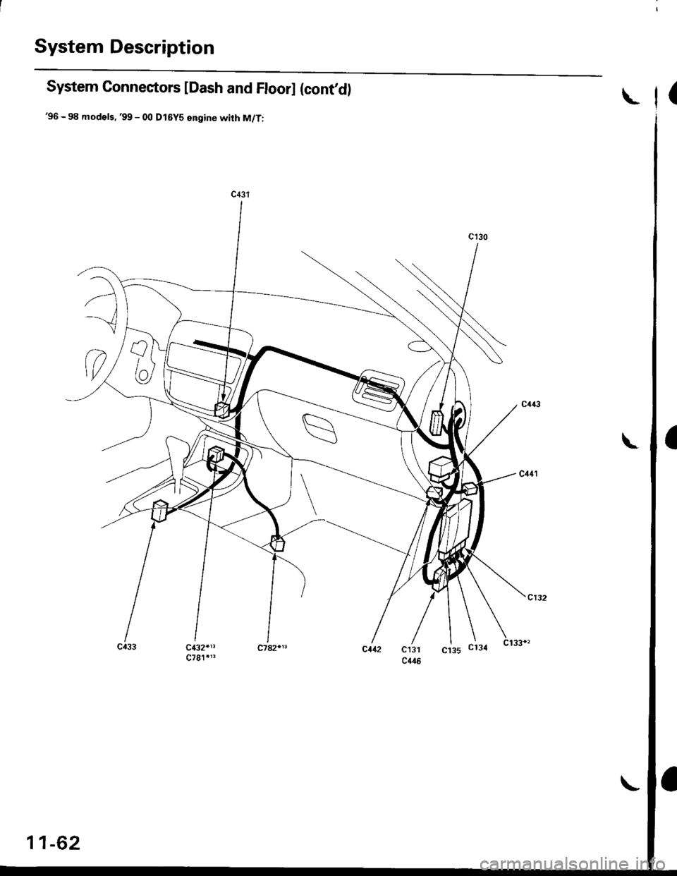
System Connectors lDash and Floorl (contd)
'96 - 98 models,'99 - 00 Dl6Y5 engine with M/T:
(
c432*13
11-62
Page 333 of 2189
![HONDA CIVIC 1998 6.G Manual Online System Description
System Connectors IEngine Compaftment]
99 - 00 D16Y5 ICVT), D16Y8 engine:
cl14 C1423
*1: USA model2: A/T {D16Y7, O16Y8 engine)*3: CVT lD16Y5 engine)*4:A/T and D16Y7 engine*5: Exc HONDA CIVIC 1998 6.G Manual Online System Description
System Connectors IEngine Compaftment]
99 - 00 D16Y5 ICVT), D16Y8 engine:
cl14 C1423
*1: USA model2: A/T {D16Y7, O16Y8 engine)*3: CVT lD16Y5 engine)*4:A/T and D16Y7 engine*5: Exc](/img/13/6068/w960_6068-332.png)
System Description
System Connectors IEngine Compaftment]
'99 - 00 D16Y5 ICVT), D16Y8 engine:
cl14 C142'3
*1: USA model'2: A/T {D16Y7, O16Y8 engine)*3: CVT lD16Y5 engine)*4:A/T and D16Y7 engine*5: Except A/T and D16Y7 engine*6: CVT {D16Y5 engine).O16YB engin€ and816A2 engine*7: D'|6Y8, 81642 engine
11-64
Page 345 of 2189
![HONDA CIVIC 1998 6.G Manual Online System Description
a
a
a
System Connectors [Dash and Floor]
(99 - fil models except D16Y5 engine with M/Tl
L
11-76
L HONDA CIVIC 1998 6.G Manual Online System Description
a
a
a
System Connectors [Dash and Floor]
(99 - fil models except D16Y5 engine with M/Tl
L
11-76
L](/img/13/6068/w960_6068-344.png)
System Description
a
a
a
System Connectors [Dash and Floor]
('99 - fil models except D16Y5 engine with M/Tl
L
11-76
L
Page 349 of 2189
![HONDA CIVIC 1998 6.G Manual Online System Descriptions
System Connectors lFuel Pump]
(9!, - 00 models 6xcept Dl6Y5 ongino with M/T)
\(
I
c568
ffi
c565
E
c792
Different wires with the same color have been given a number suffix to disti HONDA CIVIC 1998 6.G Manual Online System Descriptions
System Connectors lFuel Pump]
(9!, - 00 models 6xcept Dl6Y5 ongino with M/T)
\(
I
c568
ffi
c565
E
c792
Different wires with the same color have been given a number suffix to disti](/img/13/6068/w960_6068-348.png)
System Descriptions
System Connectors lFuel Pump]
('9!, - 00 models 6xcept Dl6Y5 ongino with M/T)
\(
I
c568
ffi
c565
E
c792
Different wires with the same color have been given a number suffix to distinguish them (for example, YEUBLKIand YEVBLK, are not the same).
O: Related to Fuel and Emissions System.- Connector with male terminals (double outline): View from terminal side- Connector with female terminals (single outline): View from wire side
c793
fr
NOTE: o
a
a
1 1-80
Page 352 of 2189
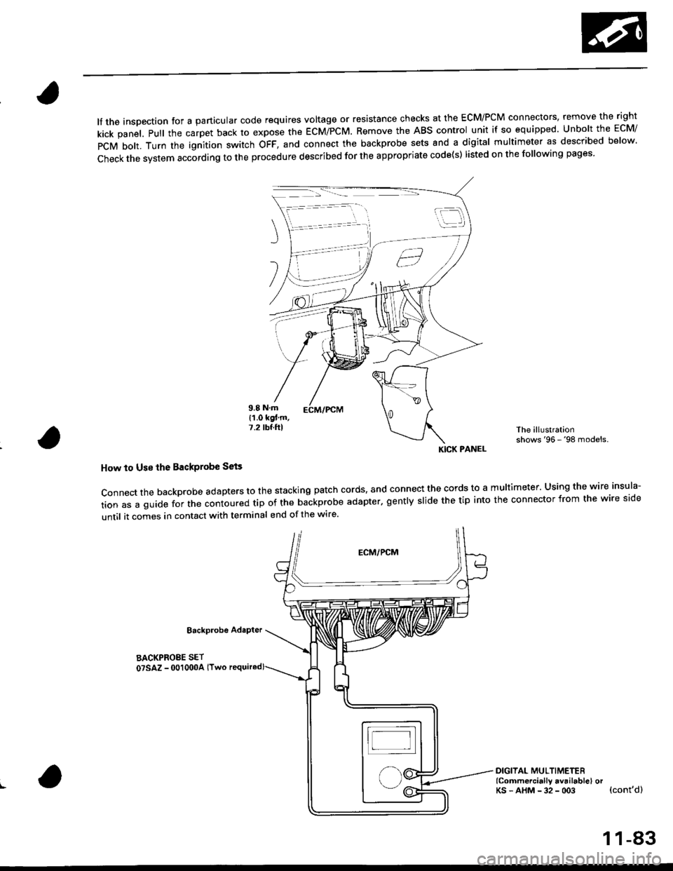
lf the inspection for a particular code requires voltage or resistance checks at the ECM/PCM connectors, remove the right
kick panel. Pull the carpet back to expose the ECM/PCM. Remove the ABS control unit if so equipped. unbolt the EcM/
PCM bolt. Turn the ignition switch oFF, and connect the backprobe sets and a digital multimeter as described below
check the system according to the procedure described for the appropriate code(s) listed on the following pages'
The illustrationshows '96 - '98 models.
How to Use lhe Backprobe Sets
connect the backprobe adapters to the stacking patch cords, and connect the cords to a multimeter. using the wire insula-
tion as a guide for the contoured trp of the backprobe adapter. gently slide the tip into the connector from the wire side
until it comes in contact with terminal end of the wire'
BackProbe
BACKPROEE SET
07SAZ - 001000A lTwo
DIGITAL MULTIMETER(Commercially avail.bleI orKs - AHM - 32 - oo3 (cont'd)
KICK PANEL
1 1-83
Page 353 of 2189
Troubleshooting
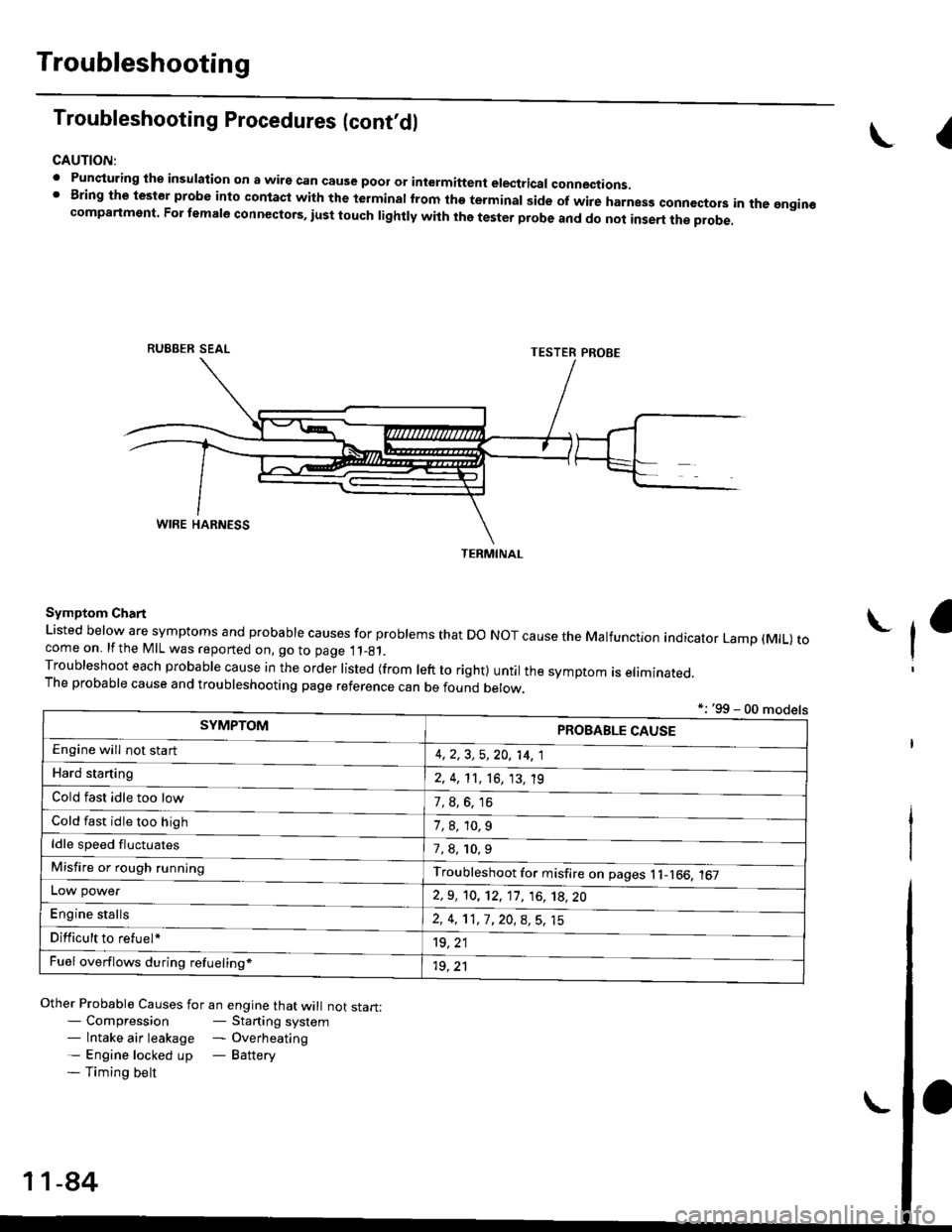
Troubleshooting Procedures (cont,dl
CAUTION:
. Punqturing ihe insulation on a wirs can cause poor or intermiftent electricar connections.I Bring the test€r probe into contacl with the terminatlrom the terminal side of wire harnesg conncctors in the gngin€compartment. For temale connectors, iust touch lightly with the tester probe and do not inse.t the probe.
\I
RUBBER SEAL
Other Probable Causes for an engine that will not start:- Compression- Starting system- lntake air leakage - Overheating- Engine locked up - Battery- Timing belt
TESTER PROBE
Symptom Chart
Listed below are symptoms and probable causes for problems that Do NoT cause the Malfunction indicator Lamp (MlL) tocome on. lfthe MIL was reported on, go to page 11_81.Troubleshoot each probabre cause in the order risted (from reft to right) untir the symptom is eriminated.The probable cause and troubleshooting page reference can be found berow.
L
*: '99 - 00 models
TERMINAL
SYMPTOMPROBABLE CAUSE
4,2,3, 5,20, 14, 1
2, 4, 11, 16, 13, 't9
?, s^6. 16
1,8,10.9
Engine will not sta rt
Hard starting
Cold fast idle too low
Cold fast idle too high
ldle speed fluctuates7,8, 10.9
Troubleshoot for misfire on pages l1-166, 167Misfire or rough running
LOW power
E"g|* "t"lb
2,9, 10, 12, 11, 16, 't8,20
2,4,11,7,20,8,5,15
't9, 21
1r, ,1
Difficult to refuel*
Fuel overflows during refueling*
11-84
Page 354 of 2189
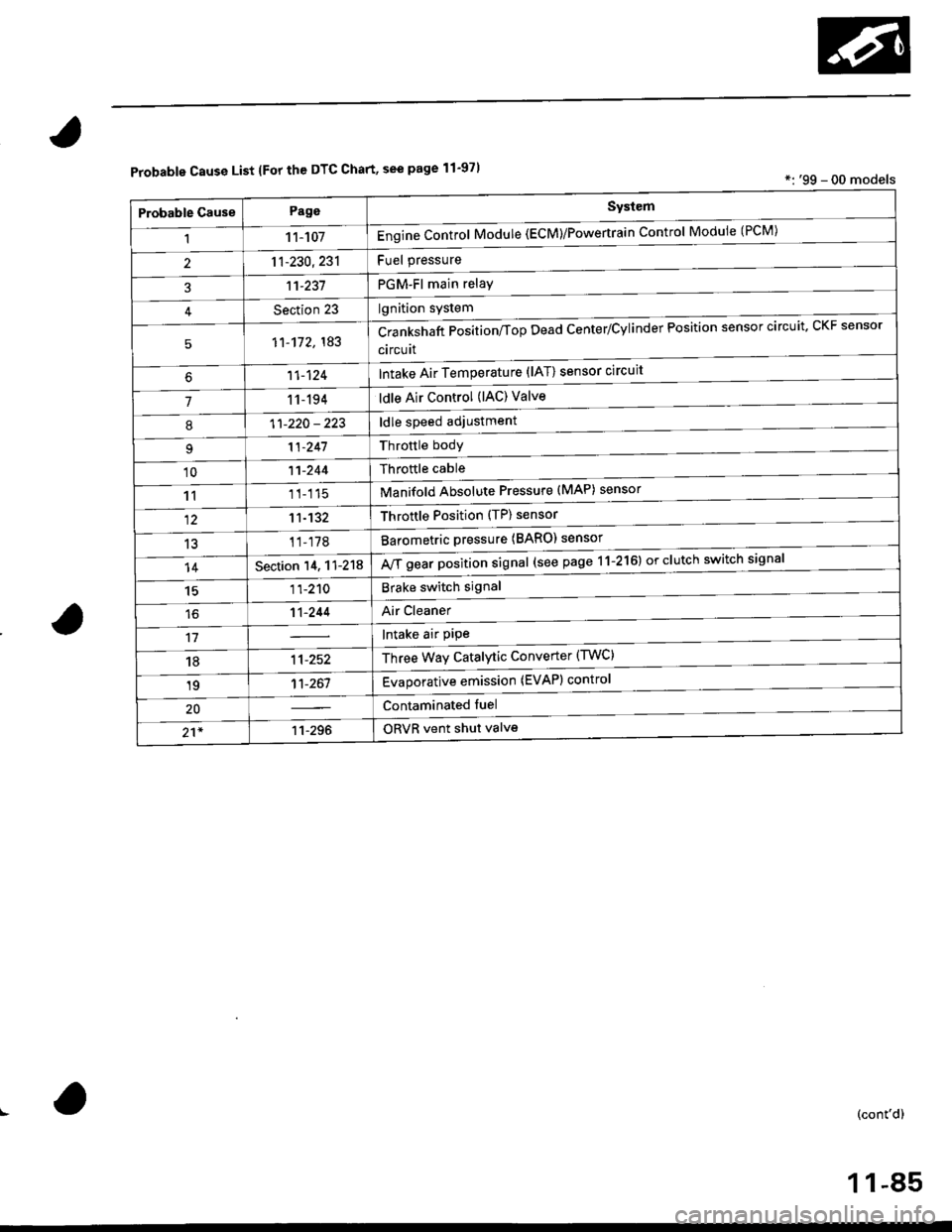
Probable Cause List lFor th€ DTC Chart, see page 11-971*: '99 - 00 models
Probable GausePageSystem
11 1-107Engine Control Module (ECM)/Powertrain Control Module (l'uM)
PGM-Fl main relay
l^^iti^n cwetam
211-230,231
3't't-237
Section 23
51'�1-172,183Crankshaft Position/fop Dead Center/Cylinder Fosltlon sensor clrculr'� Lr\F selrsor
circuit
Intake Air Temperature (lAT) sensor circuit
ldle Air Control (lAC) Valve
ldle speed adjustment
Throttle bodY
Throftle cable
Manifold Absolute Pressure (MAP) sensor
Throftle Position (TP) sensor
Barometric pressure (BARO) senso'
Mf g"a, po"ition signal (see page 11-216) or clutch switch signal
Brake switch signal
Air Cleaner
lntake air pipe
Three Way Catalytic Converter (TWC)
Evaporative emission (EVAP) control
Contaminated fuel
ORVR vent shut valvs
't1-124
71 1-194
I11-220 - 223
11-241
'1011-244
1111-115
1211-132
13't1-178
14Section 14. 11-218
1511-210
16't1-244
1811-252
1911-261
20
21*11-296
(cont'd)
11-85
Page 357 of 2189
Troubleshooting
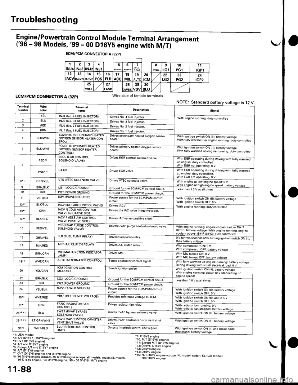
E n gine/P_o,weft ra in Control Module Term inal Arra n gement('96 - 98 Models, '99 - 00 Dl6yS engine with M/T)
-
ECM/PCM CONNECTOR A I32PI
1INJ62INJ3INJ21
INJl567I
LG110PGll1
IGPl12
ACV
131115
PCS
16
FLR17acc18MIL19ALTC20
tcM22PG221IGP2272A25
VSV30
SLU
ECM/PCM CONNECTOR A (32P)
'2: A./T (D16Y7, 016Y8 engine)13: CvT (D16Y5 enoin€)',4: A/T and D16y7 engine*5: Except A/T and D16Y7 €nsine'6r A/T (D16Y8 ensine)'7 Cw 1D16Y5 eng,nel and D16y8 ensrne'"'3:Bi..I?'Jt;".'e'.!ti.?i?l'""."T8"_";btfr
"fl
1-88
Wire side of female terminals
NOTE:Standard battery voltage12ts
'10i i,4/T (D16V5 engine)r11 Ex.ept M/l (D16V5 enqinelr12: 016Y5, D16YB enqine
r15:'97 016Y7 engine lcoupe: KL modet, sedan: KL (LXl modet),'98 D16Y7 engine
1
1
Sign.l
YELlNJ4 (No.4 FUEL INJECIOB)D ves No 4 ruel injector.Wilh engine runninq: ddly coniroted2BLUlNJ3 lNo. 3 FUEL TNJECTOBJDrives No. 3 lue Inteclor.38EDINJ2 (NO, 2 FUEI INJECTON)Drives No. 2 iuel njector.88NlNJl (No. 1 FUEL INJECTOB)Dives No. 1 ruelinjector.
5SO2SIITC (SECONDAFY HEATEDOXYGEN SENSOF HEATEF CONTFOL)
Orives secondary heated oxyqen sensorWith ignilion switch ON (lll: batery vo lageWith f!llywarmed up engine runninq:dLtv controled
6BLXAVHTPO2SHTC (PRIMAFY HEATEOOXYGEN SENSOR HEATERCONTROL)
Drives prihary healed oxygen sensorWith ignition switch ON ltt):baneryvottasewlhrdllywdrmedupcngne,Lnnrrq dury,orl.otred
FED{ESOL (EGF CONTRO!SOIENOIO VALVE)Drives EGF conlrolsoleno d vatve.Wilh EGR operating during drving wiih fu|y warmedup engrne: duty controttedWilh EGF nol opefating:O VE.EGRWith EGF operating du.ing driv og wilh iuty warmedup en9ine: dutycont.olted.With EGR not ooeralino; o V8*r/GFN/YELWS (VTEC SOLENOTD VALVE)Drives VTEC solenoid va veWilh eng ne at ow engine speed:O VWirh engine at h gh enqine speedr banery vohaae9BflN/BLKLG1 (LOGIC GROUND)Gro!nd lorthe €CM/PCM conlrotc rcuit.Lesslhan 1.0 V at a ttimest0ALKPG1 IPOWEF GFOUND)Ground ior rhe ECM/PCM power.tcuf.11YEVBLKIGPT iPOWEF SOUFCE)Power source forthe Ec[,l/PcM conlroWilh ignition swirch ON (tt): battery voltageWith gntron switch OFF: 0 VBLVBLUIACV (IDLE AIN CONTROL VALVE)Wilh engine r!nn ng: dlty contro ed13,.o8NIACV N lIDLE AI8 CONTFOLVALVE NEGATIVE SIOE)Drivesthe IAC valve {negalive side).
BLVBLUIACV P (IDLE AI8 CQNTROLVALVE POSITIVE SIDE)Orives IAC vaive (posilive side).
FEO/YELPCS (EVAP PURGE CONTFOTSOIENOIOVALVE)Drives EVAP pu.ge controtsolenoid vatve.Wilh engioe running, engin€ cootani betow 154,F'68'Cr bancry vohaSe w'ln ens nc runn,.o. eng,rc
GRN/YELFL8 (FUEL PU[4P FELAY)Orives fuelpump relay.0 V {or two secor os ahe' tJ n ng 'onir or \wnch ON ,,,,,
I7BLI(REOACC (A,/C CLUTCH RELAY)Drives A/C clutch relay.Wirh compressor ONr0 VWilh compressof OFF:banery votrage18GFN/ONNMIL (I\,lALFUNCTION INDICATOFWith MIL lLrned ON: 0 VWith illl turned OFF: banery volaqe19',AITC {AITERNAIOR CONIROL)se.ds ahernator controt signat.Wirh fully warmed.up engine ru.ntng: battery votlas€During drivins wnh smatl eteclricat toad: O V
20YEVGRNICM (IGNI'TION CONTROLMOOU!E)with ignltlon swilch ON (tl):b6n€ry vohageWilh ensine runnins: aboul t0 V (depending on
22BRN/BLKLG2 (LOGIC GAOUND)Ground for the ECM,/PCM conrrot ci'cu LLess than 1.0 V at a tt mes23BLKPG2 iPOWEA GROUND)Gro!nd lor the ECM/PCM power circuir.24YEUBLKlGP2 (POW€R SOUSCE)Power sou.ce lor the ECM/PCl, conrrolWnh ignilion swilch ON {it):battery vohageWilh ignilion switch OFF:0 V25*6WHT/FEDVSEF IREFEfl ENCE VOLTAGE)Provrdes reference voIaOe to TCM.With ignition switch ON (tt):abour 5 VWth gnition swltch OFF: O V21'1GFNFANC {RAOIATOR FANCONTFOL)Drives radialof fan ielay.With radialor fan f!nn nqr O VWilh radiato.tan stopped: batteryBL!2WBS (EVAP BYPASSSOLENOIO VALVE]Orives EVAP bypass sotenotd va !e.With ignirion swrrch ON (tt):barery vo rase
LT GRNA/VHTVSV (EVAP CONTFOTCANISTEFVENT SHUT VAIVE)Drives EVAP conlfot canisrer venl shulwnh ignirion sw'tch ON lr|l barery volaqe
WHT/NEDSLU (INTEFLOCK CONTFOLUNIT)Detects intenock conlrotLn t signalWhh ignition switch ON (tt)and brake pedadepf essed: battery vollage