C442 HONDA CIVIC 1998 6.G Workshop Manual
[x] Cancel search | Manufacturer: HONDA, Model Year: 1998, Model line: CIVIC, Model: HONDA CIVIC 1998 6.GPages: 2189, PDF Size: 69.39 MB
Page 1508 of 2189
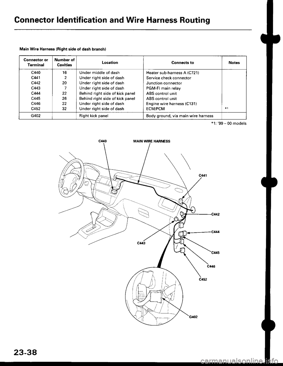
Gonnector ldentification and Wire Harness Routing
Msin Wire Harness (Right side oI dash branch)
Connector or
Terminal
Number of
CavitiesLocationConnects toNotes
c440
c441
c442
c443
c4M
c445
c446
c452
16
2
20
7
22
22
Under middle of dash
Under right side of dash
Under right side of dash
Under right side of dash
Behind right side of kick panel
Behind right side of kick panel
Under right side of dash
Under right side of dash
Heater sub-harness A (C721)
Service check connector
Junction connector
PGM-Fl main relay
ABS control unit
ABS control unit
Engine wire harness (C131)
ECM/PCM
G402Right kick panelBody ground, via main wire harness
*'l: '99 - 00 models
23-38
Page 1821 of 2189
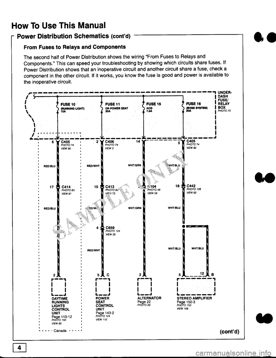
How To Use This Manual
Power Distribution Schematics (cont'd)
From Fuses to Relays and Components
The second half of Power Distribution shows the wiring "From Fuses to Relays and
Components." This can speed your troubleshooting by showing which circuits share luses. lf
Power Distribution shows thal an inoperative circuit and another circuit share a fuse, check a
component in the other circuit. lf it works, you know the fuse is good and power is available to
the inoDerative circuit.
oa
UNDER.DASHFUSE/RELAYBOXI i *. to i ru..'.' l * tt I tust tt
){nuo$rouc}rr) }g*"""' }tS }ff***,
\
I
,
I-- - ----\&- -----J-------ir
9,s9:,.,
,.,'li"'"rr' ' 'rll$vryglu
:
]:l. ,' "'':r.,
,:ti. .:1,,.,
*_lu*'.
'71ffi"�
- -t**,-
vtEw &
04 18 g C442
2A
tl
12 .L e
tl
ALTENNATORPaoe 22PHdro 29
ll
tlL------JSTEREO AMPLIFIERPaoe 150-3PHdfo 1s3vtEw 106
121
'f,"c;93,. : '� f,t'ffi
lv'Ew6o ! 1,.",
l:lN'll
^.o,r.u I i ".o,*", I
l:t
l,l
u*,.11,2", i "l9*',g
11""" : l*'-
l:lnEDisLu
|
; . ED,w' (
I'lP:ll
! " : .1".,9t3
q - '
I v'Ew3e
h;ll
l:ll
I : FED^rir{r
i
l:i
tii
,.L i slc
r--1 : r--1
tt:ll
ltlllt--J ' l--JDAYTIME : POWERRUNNING ; SEATLIGHTS . CONTROLCONTROL . UNITUNIT ' Paoe 143-2paoe 1to-j2 t PHdro t2.PHdTo 1so i wEw 110vtEw 65
- - -' Canada '_ _ _(cont'd)
Page 1858 of 2189
----" A/T -----t
DRIVEN PULLEY , ^.,.
;iftTBilis'".f l5Ftr,.""_
co'rinienixnn '. Pase 23'2
SPEED SENSOR ; .'-\.SHIELD 'F--.1
TDC/CKP/CYPSENSORSHIELDPage 20
ll
r_:.-i
23-13
t1
23- l4
tl
PRIMARY SECONDARYHO2S HO2SSHIELD SHIELDPages 23-8, Pages 23-9,23-10. and 23-11. and
--- CW ----.
TRANSMISSION ;CONTROLMODULE(TCM) ,Page 39-5 :PHO|O 121vlEw 69r____1 ,
tt:
tt:L----J,
. D16Y8engine
SECONDARY .
HO2S :SHIELD ;Page 23-11
l. - -..1 ;
tt:(D16Y/i D15Y8)Page 39-1
l.--.1
1l
r:--iBFN/BLKARN/BLK
A4
6FN/BLK' EFN/BI
i i srco"oo"t :' I GEAR SHAFT
I I Or MAtN!'tAt I. II SPEED SENSOR '
CW. - D16Y8 -, engine: N SENSoR SHTELD ,
i !i?il3li*u,, i
CWSHIELD :Page39-4,
CRANK-SHAFTSPEEDFLUCTU-ATION(cKF)SENSORPage 23-2
tl
ll
;I;..
26
i xNocx' SENSOR, (KS)' SHIELD
, Fage zJ-5
: F--.1
:ll
iilr-:i
----:.--------:
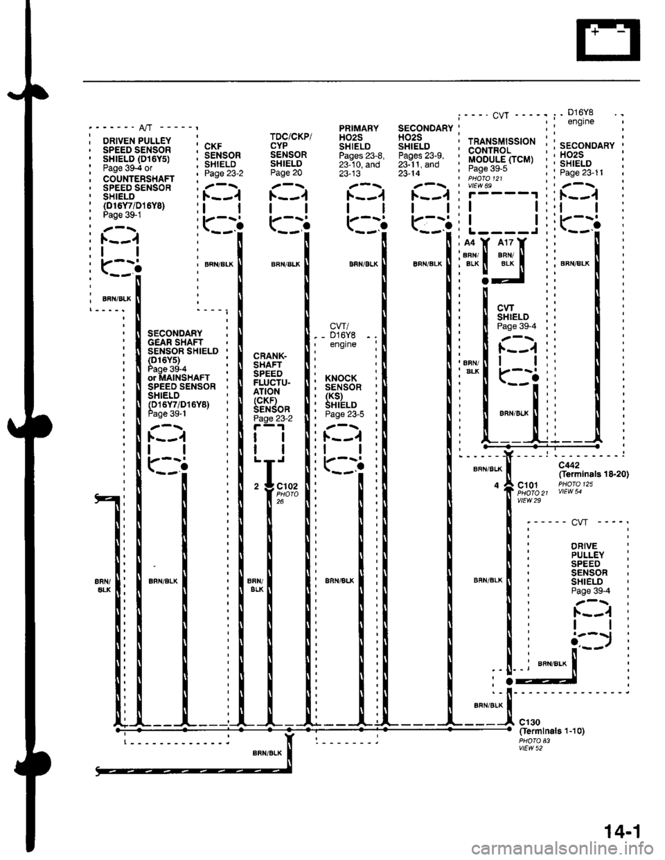
c442(Terminals 18-20)
c10.1 PHofo 125\HOTO 21 VIEW 54vtEw 29
'----- cw ----'
DRIVE
BFN/BLK
PULLEY :SPEEDSENSORSHIELDPage 39-4 :
1.---{ :I t;
cl30Oermlnal8'l-10)
vtEw 52
14-'�,
Page 1874 of 2189
POWEBTRAINor ENGINECONTROL MODULE(PCM or ECM)
vtEw 70
lgnitionoulputsignatflcM)
I
YEUGBN
c'120
vtEw 29
DISTRIBUTOR
D1685 -------,
BLU
_9-
BLU
8
9LU
:'!'\?- - -
c101
vtEw 2a
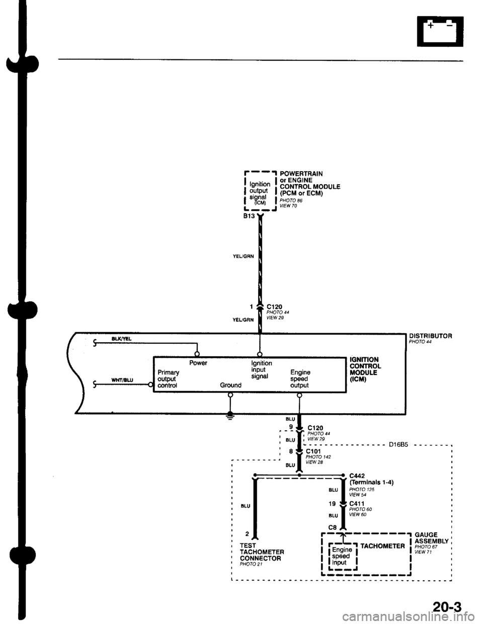
----------<- c442
I frerminals 1-4]a|-u a olo'25 |I vlEw 54
19 g C411a PHOTA 60aru I vtrw ool,cBA- -.t GAUGF
i f#f rAcHoirErER ift?i,?""i
liitr" i !I L--J IL ---- - --- -J
TESTTACHOMETERcor.rNEcToRPHO|O2l
lgniiionnrpur Fh^ih-signal "p_il;Ground output
PrimaryoutPutcontsol
20-3
Page 1978 of 2189
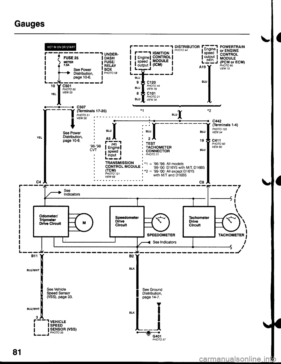
Gauges
#'t----lllgi' i i-r-; ffiffig'i
;;;;6;;- -
ild;$ i fr{li,l[i
1 OTSTR|BUTOR r--- --.-^'l POWERTRATN
![ElF{, I i:tirtiifffii* I ":"+J (pclrrorEcM)
I
t**"**
iB,HFf ! L"T-liidfri" | ^i,i'llt"#,*'
-i]_Lryq_j""""
..-:i:I1;,,?--.,
_,1
lllftT":{"
r:l #f,t, I
! v,ersoI -!'Yv , I :"
c442
#* i ;[. r;{ 11;:#r i :;l i1[---- 11 :ff:*"'"'
'i" f+Taj i!!3lo_rrr."
SeeIndicators---{
rAcnoMErER i
I
sfr" iFSil i il"+"+w "-1itl*""
' LuqJ I F*l$"
I
i mi+',ts'fi8$,* i'' =,i!,,ii.ii:yil',g",',0,u,,
It, fri;J,, :,
-;;;U,+*r;l'd*o',
", I-7
I
I
I
I
\
\
\
I
-l
L82"'I
"'u'"'!
I s,#!,,*",
!
Nsst, oaoe so.
""1,i,
r--'! vEHtcLE! I SPEED
L__j;,#39'n.',
S€€ GroundOistribution,page 1+7.
Y
I
I
I+: c4ol
SPEEDOMElER
Page 2007 of 2189
![HONDA CIVIC 1998 6.G Workshop Manual Brake Lights
- All Coupes and96-98 Sedans
tl
UNDER-HOODFUSE/RELAYBOX
?-------
i t t!::o i
i ) SrTIr gee Power iI t 154 Distribution,
L--E-]-p3n:"1--.:
Without Cruise Control
See PowerDistribution,p HONDA CIVIC 1998 6.G Workshop Manual Brake Lights
- All Coupes and96-98 Sedans
tl
UNDER-HOODFUSE/RELAYBOX
?-------
i t t!::o i
i ) SrTIr gee Power iI t 154 Distribution,
L--E-]-p3n:"1--.:
Without Cruise Control
See PowerDistribution,p](/img/13/6068/w960_6068-2006.png)
Brake Lights
- All Coupes and'96-'98 Sedans
tl
UNDER-HOODFUSE/RELAYBOX
?-------
i t t!::o i
i ) SrTIr gee Power iI t 154 Distribution,
L--E-]-p3n:"'1--.:
Without Cruise Control
See PowerDistribution,page 1013.
BNAKE SWITCHClosed with brakepedal depressed.PHOTO 68
8 Y C3s2*nrlo." I i[o"'r?, *"r,o"no----awHr/GFN iWith Cruise Control t
*"r,n*[ ,r"r,o*[
r t 1 BRAKE SWTTCH l-'rt
LQlt'*'*t'**" l4J
n""n",.tr I o""*,1, !
o"*n"", I
*=Male-Female
terminals reversedfor '99-'00 models
GFN/II/HT13('99100 models except GX 17)GFN^^/HT2('99-'00 models except GX 10)
GFNMHT
c442fferminals'l ! -14)
PHO|O 125vtEw 54
c401
c563
(C562 '99100 models except GX) *
V|EW 42 GFN,ryVHT
Withoutoptional spoiler
r-
tPGM.FI\
withoptional spoilarGAN/
GFN/
BLK
110-15
+ 9,6,91o,",
\a
Page 2123 of 2189
Connector Views (cont'd)
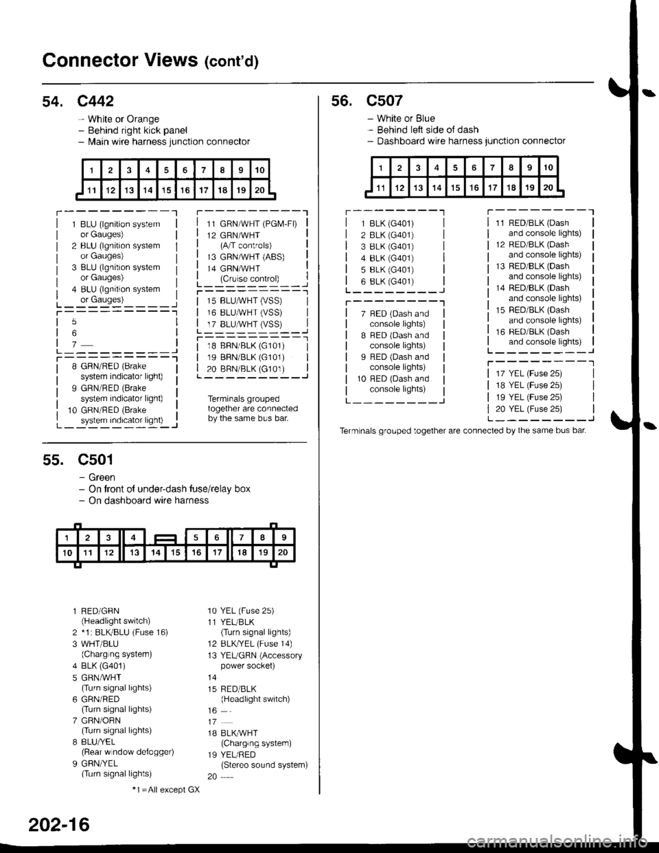
54. c442
- White or Orange- Behind right kick panel- l\,lain wire harness junction connector
r---------Tr---------"1
1 BLU (lgnition systemor Gauges)
2 BLU (lgnition syslemor Gauges)
3 BLU (lgnition systemor Gauges)
4 BLU (lgnition system
L_ or causes)L_-:-:::'-'�____Jt-----------1
11 GRN/WHT (PGM-FD
12 GRN/WHT(A/T controls)
13 GRNMHT (ABS)
14 GRNMHT
L_ lc,r'." .oIr"D_ _ _.jr----------_l
5
6
7L---------JT----------l8 GRN/RED (Brake
system indicator light)
9 GRN/RED (Brake
system indicator light)
10 GRN/RED (Brake
_ system indicator ligh0 -..1
| 15 BLUMHT (vSS) |I 16 BLUMHT (VSS) I
L T?_BLUSTrySS)--..]
l--------- - -l
| 18 BFN/BLK (G101) I| 19 BBN/BLK (G101) || 20 BRN/BLK (c101) |L---------J
Terminals groupedtogether are connectedby the same bus bar.
55. C501
- Green- On tront of under-dash tuse/relay box- On dashboard wire harness
l RED/GFN(Headlight switch)
2 *1 : BLKBLU (Fuse 16)
3 WHT/BLU(Charging systern)
4 BLK (G401)
5 GRNMHT(Turn signal lights)
6 GRN/RED(Turn signal lights)
7 GRN/ORN(Turn signal lights)
8 8LU/YEL(Rear w ndow delogger)
9 GFN/YEL(Turn signal lights)
'10 YEL (Fuse 25)
11 YEL/BLK(Turn signal lights)
12 BLKTYEL (Fuse 14)
13 YEUGRN (Accessorypower socket)
15 RED/BLK(Headlight switch)
1B BLK/WHT(Charglng system)
19 YEL/RED(Stereo sound system)
20
202-16
-1 =All e),cept GX
s6. c507
- White or Blue- Behind left side oJ dash- Dashboard wire harness junction connector
r --------'lT---------l
7 BED (Dash andconsole lights)
B BED (Dash andconsole lights)
I RED (Dash andconsole lights)
10 RFD (Dash andconsole lights)
11 RED/BLK (Dash
and console lights)
12 RED/8LK (Dash
and console lights)
13 RED/BLK {Dashand console lights)
14 RED/BLK (Dash
and console lights)
15 RED/BLK (Dash
and console lights)
16 RED/BLK (Dash
and console lights)L--------J
T--------T
L---_---_J
1 BLK (G401)
2 BLK (G401)
3 8LK {G401)4 8LK (G401)
5 BLK (G401)
6 8LK (G401)L________J
T--------"1
17 YEL (Fuse 25)
18 YEL (Fuse 25)
19 YEL (Fuse 25)
20 YEL (Fuse 25)L--------J
Term nals grouped together are connected by the same bus bat
Page 2167 of 2189
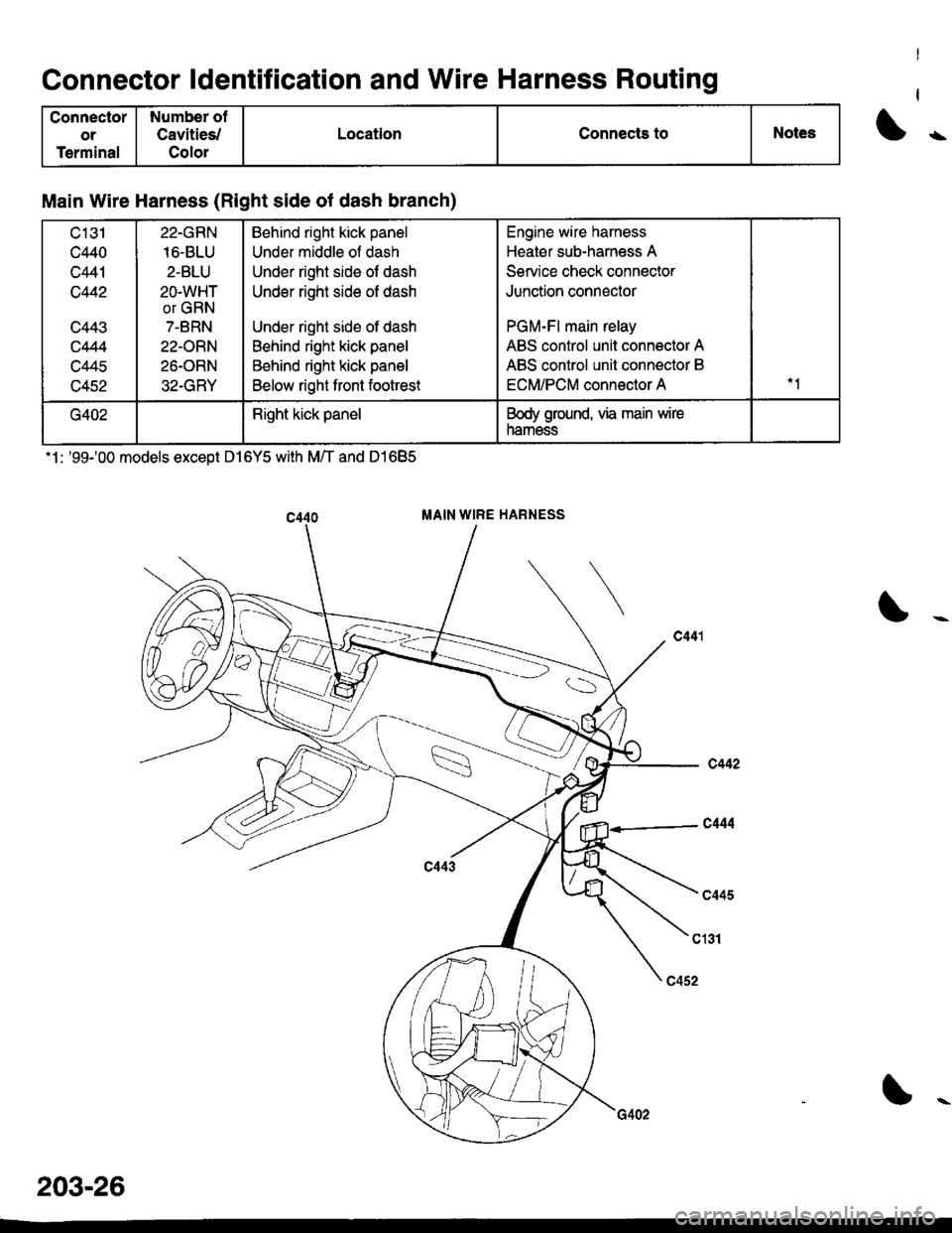
Connector ldentification and Wire Harness Routing
Connector
or
Terminal
Number ol
Cavities,/
Color
LocationConnects toNotes
Main Wire Harness (Right side of dash branch)
c131
c440
c441
c442
c443
c444
c445
c452
22.GRN
16-BLU
2.BLU
2O-WHT
or GRN
7-BRN
22-ORN
26-ORN
32.GRY
Behind right kick panel
Under middle of dash
Under right side of dash
Under right side of dash
Under right side of dash
Behind right kick panel
Behind right kick panel
Below right front footrest
Engine wire harness
Heater sub-harness A
Service check connector
Junction connector
PGM-Fl main relay
ABS control unit connector A
ABS control unit connector B
ECM/PCM connector A
G402Right kick panelBody ground, via main wire
namess
.1 : '99100 models exceot D l6Y5 with M/T and D1685
MAIN WIRE HARNESS
203-26