Remove the AC thermostat HONDA CIVIC 1998 6.G Workshop Manual
[x] Cancel search | Manufacturer: HONDA, Model Year: 1998, Model line: CIVIC, Model: HONDA CIVIC 1998 6.GPages: 2189, PDF Size: 69.39 MB
Page 266 of 2189
EGT Switch
-f
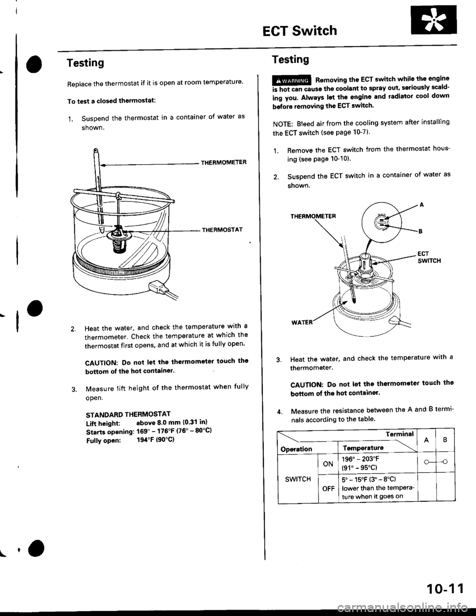
Testing
Replace the thermostat if it is open at room temperature'
To test a closed thermostat:
1, Suspend the thermostat in a container of water as
shown.
THEBMOMETER
THERMOSTAT
Heat the water, and check the temperature with a
thermometer. Check the temperature at which the
thermostat first opens, and at which it is fully open
CAUTION: Do not let the thermometer touch the
bottom of the hot Gonlainel.
Measure lift height of the thermostat when fully
open.
STANDARD THERMOSTAT
Lift height above 8.0 mm (0.31 inl
Starts opsning: 169' - 176'F (76' - 80'Cl
Fully open: 194'F {90"C1
!'o
10-1 1
Testing
!!@ Romoving the EcT swhch while lhs engine
i!-ot can cause the coolant to sPray out, seriously scald-
ing you. Always lst th€ ongine and rediator cool down
before removing ihe ECT switch.
NOTE: Bleed air from the cooling system after installing
the ECT switch (see Page 10-7)
1. Remove the ECT switch from the thermostat hous-
ing (see Page'10-10).
2. Suspend the ECT switch in a container of water as
shown.
Heat the water, and check the temperature with a
thermometer.
CAUTION: Do not let the thermomoter touch tho
bottom of the hot container'
Measure the resistance between the A and B termi-
nals according to the table.4.
Terminal
Oo"rffi
swlTcH
ON196' - 203"F
(91" - 95'C)o--o
OFF
5" - 15'F {3" - 8'C)
lower than the temPera-
ture when t goes on
Page 1429 of 2189
Description
Outline
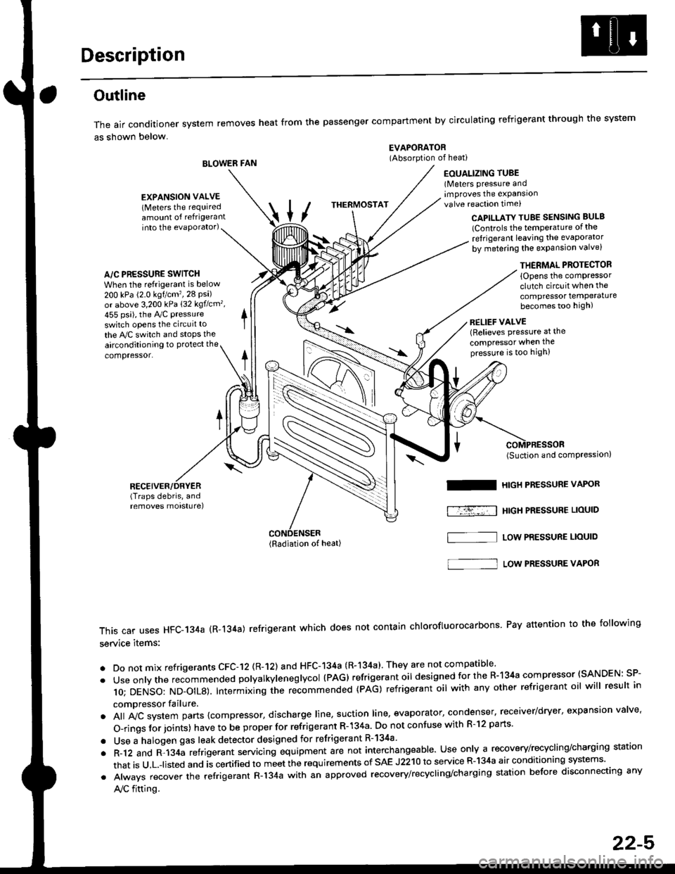
The air conditioner system removes heat from the passenger compartment by circulating refrigerant through the system
as shown below.
BLOWER FAN
EVAPORATOR(Absorption of heati
EOUALIZING TUBE(Meters pressure andimproves the expansionvalve reaction time)
into the evaporator)CAPILLATY TUBE SENSING BULB
lControls the temPerature of the
ref rigerant leaving the evaporator
by metering the expansion valve)
/\
THERMOSTAT
A/C PRESSURE SWITCH
When the refrigerant is below
200 kPa (2.0 kgtcm'�,28 Psi)or above 3,200 kPa 132 kgflcm',
455 psi), the Ay'C pressure
switch opens the circuit to
the A,/C switch and stops the
EXPANSION VALVE(Meters the requiredamount of refrigerant
airconditioning to Protect the
compressor.
RECEIVER/DRYER(Traps debris, andremoves morsturel
THERMAL PROTECTOR
{Opens the comPressorclutch circuit when the
compressor temPeraturebecomes too high)
RELIEF VALVE(Relieves pressure at the
compressor when thepressure is too high)
(Radiation of heat)
I
f-r-�-; I
(Suction and comPression,
HIGH PRESSURE VAPOR
HtGH PRESSUBE LIOUID
LOW PRESSURE LIOUID
This car uses HFC-134a (R-134a) refrigerant which does not contain chlorofluorocarbons Pay attention to the following
service items:
. Do not mix refrigerants CFC-12 (R-12) and HFC-134a (R-134a)' They are not compatible'
. Useonlythe recommended polyalkyieneglycol (PAG) refrigerant oil designedforthe R-134a compressor (SANDEN: SP-
10; DENSO: ND_OIL8). Intermixing ihe re-commended (pAG) refrigerant oil with any other refrigerant oil will result in
compressor failure.
. All A,,ic system parts {compressor, discharge line, suction line, evaporator, condenser, receiver/dryer, expansion valve'
O-rings for joints) have to be proper for refrigerant R- 134a Do not confuse with R-l2 parts'
. Use a halogen gas leak detector designed for refrigerant R-134a
. R-12 and R-134a refrigerant servacing equipment are not interchangeable. Use only a recovery/recycling/charging station
that is u,L.-listed and is certified to meet the requirements of sAE J2210 to service R-134a air conditioning systems'
. Always recover the refrigerant R-134a with an approved recovery/recycling/charging station before disconnecting any
A,/C fitting.
S]
22-5
Page 1445 of 2189
A/C ThermostatRelays
Test
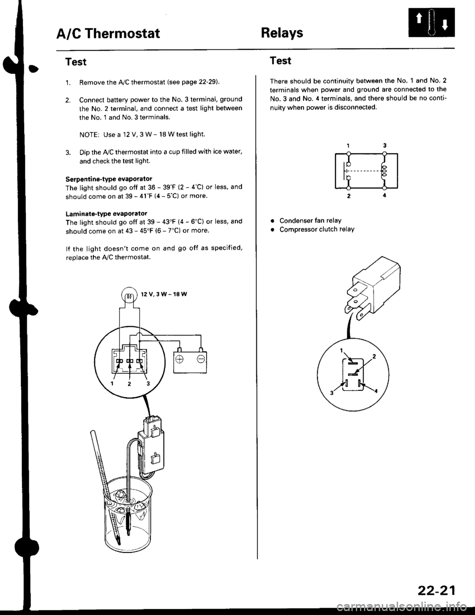
1.Remove the Ay'C thermostat (see page 22-29).
Connect baftery power to the No. 3 terminal, ground
the No. 2 terminal, and connect a test light between
the No. 1 and No. 3 terminals.
NOTEr Use a 12 V,3 W- l8 W test light.
Dip the IVC thermostat into a cup filled with ice water,
and check the test light.
Serp6ntine-type evaporator
The light should go off at 36 - 39'F {2 - 4"C} or less, and
should come on at 39 - 41"F (4 - 5"C) or more
Laminale-type evaporator
The light should go off at 39 - 43'F (4 - 6'C) or less, and
should come on at 43 - 45"F (6 - 7'C) or more
lf the light doesn't come on and go off as specified,
replace the PVC thermostat.
12V,3W-18W
Test
There should be continuity between the No, 1 and No.2
terminals when power and ground are connected to the
No.3 and No. 4 terminals, and there should be no conti-
nuitv when Dower is disconnected.
2
Condenser fan relay
Compressor clutch relay
a
a
,I Ib
In Io'r I
t\----,'
t:n
,,l[4..-.
22-21
Page 1452 of 2189
Evaporator
1.
Replacement
4.
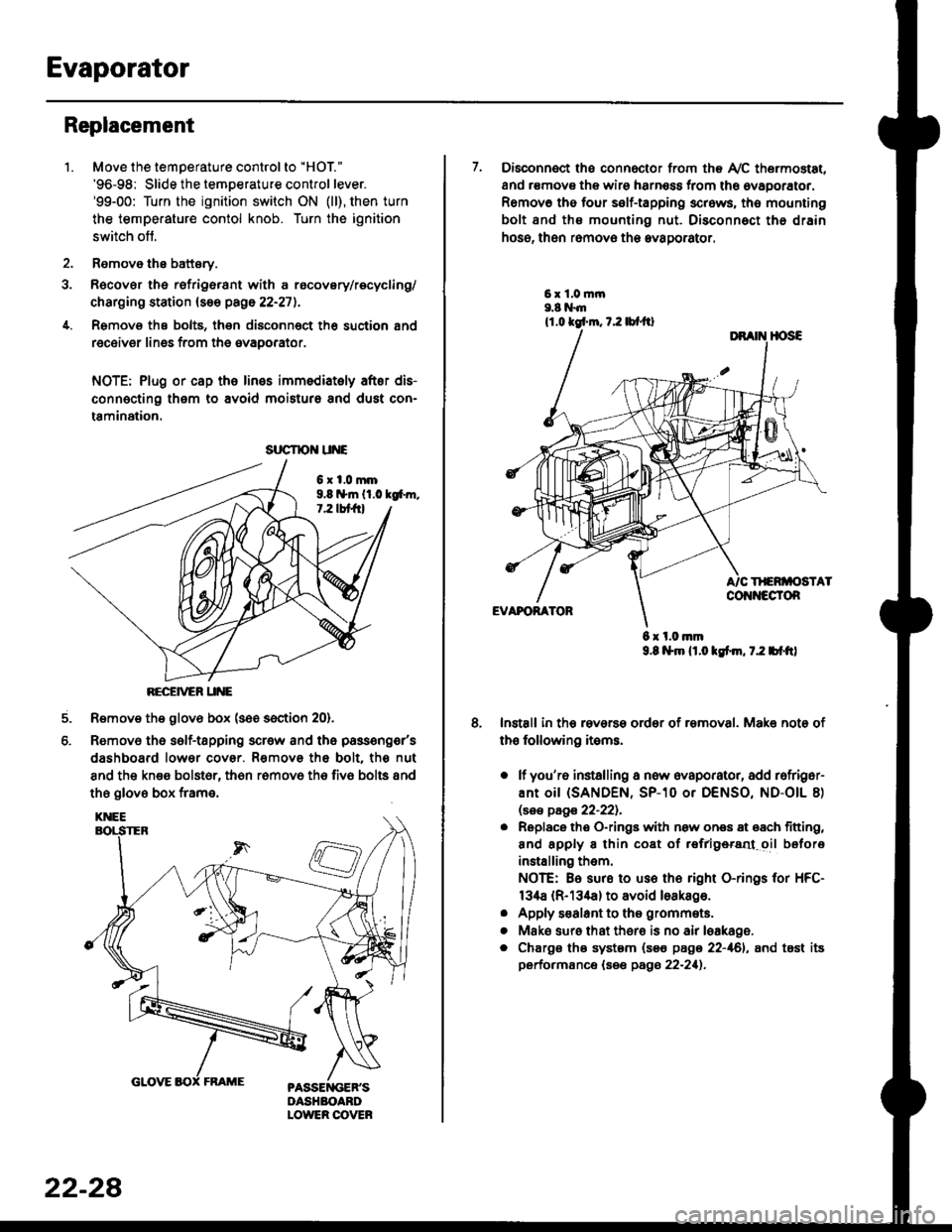
Move the temperature control to "HOl"
'96-98: Slide the temoerature control lever.'99-00: Turn the ignition switch ON (ll), then turn
the temperature contol knob. Turn the ignition
switch off.
Remove the battsry.
Rgcover the refrigerant with a rocovery/recycling/
charging station (see page 22-271.
Remove the bolts, then disconnect th6 suction 8nd
receiver lines from th6 evaoorator.
NOTE: Plug or cap the lines imm€diatoly after dis-
connecting them to avoid moisture and dust con-
tamination.
6xl.0mm9.8 n*ln ll.0 tg6m.7.2 lbt frl
RECEiVER UNE
Remove the glov6 box (see section 20).
Removo the self-tapping scr€w and the passeng€r's
dashboard lower cover. Removs the bolt. the nut
8nd the kn€e bolst6r, th6n r6mov6 th6 fiv6 bolts and
the glove box frame.
6.
srrcrrc u E
22-28
7. Disconnect the connector from th€ Ay'C thermostat,
and r€movs the wire harness from the ovaporator.
Remov6 tho four self-tapping screws, tho mounting
bolt and ths mounting nut. Disconnect th€ drain
hose, then remov€ th6 avagorator.
6 x l.0.nm9.8 l$m lt.o ldm, 7.2 bl.tt)
Install in the reverse order of removal. Make note of
th€ following items.
o lf you'r6 installing a new evaporator, add rofriger-
ANt OiI {SANDEN, SP-10 Or DENSO, ND-OIL 8)
lsas page 22-221.
. Replace the O-rings with now ones 8t 68ch titting,
and apply 8 thin coat of r€frlgersd oil before
installing them.
NOTE: Be sure to use the right O-rings for HFC-
134a (R-134a) to avoid loakago.
. Apply s€alant to tha grommets.
. Mske sure that ther€ is no air leakage.
. Chargs ths system {s€€ page 22-161, and tost its
performance (see pags 22-211.
Page 1453 of 2189
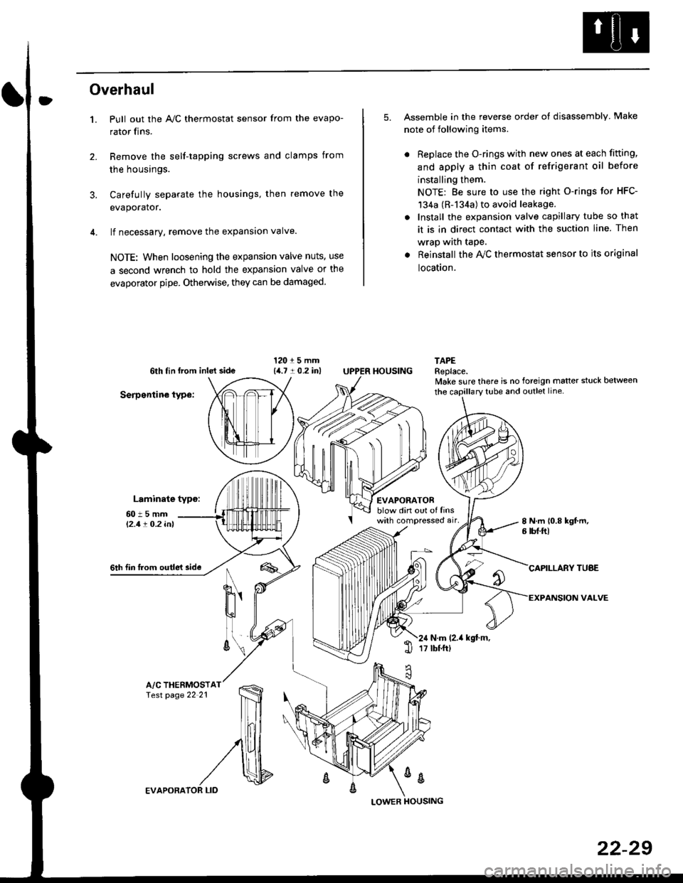
Overhaul
1.
3.
Pull out the A,/C thermostat sensor from the evapo-
rator fins.
Remove the self-tapping screws and clamps from
the housings.
Carefully separate the housings, then remove the
evaporator.
lf necessary, remove the expansion valve.
NOTE: When loosening the expansion valve nuts, use
a second wrench to hold the expansion valve or the
evaporator pipe. Otherwise, they can be damaged
5. Assemble in the reverse order of disassembly Make
note of following items.
. Replace the O-rings with new ones at each fitting,
and apply a thin coat of refrigerant oil before
installing them.
NOTE: Be sure to use the right O-rings for HFC-
134a (R-134a) to avoid leakage.
. Install the expansion valve capillary tube so that
it is in direct contact with the suction line. Then
wrap wath taPe.
. Reinstall the Ay'C thermostat sensor to its original
location.
6th tin lrom inld side
Serpentine type:
Laminate typo:
TAPEReplace.lvake sure there is no foreign matter stuck between
60t5mml'2.1! O.2 inl
EVAPORATORblow din out of linswith compressed air,
HOUSING
8 N.m 10.8 kgt m,6 tbf.ftl
6th fin lrom outle't sideCAPILLARY TUAE
VALVEN
u'
ll
6\N.m (2.it kgt.m,17 tbtftl1l
A/C THERMOSTfesr page 22 21
%
EVAPORA
LOWER
22-29
Page 1957 of 2189
- How the Circuit Works
Battery voltage is supplied through tuse 56 to the
A,/C compressor clutch r€lay contacts at all times.
With the ignition switch in ON (ll), vollage is applied
to the coil of the A,/C compressor clutch relay
through fuse 17. When you push the A,/C switch
ON, and the heater fan switch is in position | , 2, 3,
or 4, a "ground" input is provided to the engine
control module (ECM) or powertrain control module
(PCM) through the l'lC thermostat and the l'lC
pressure switch.
The A,/C compressor clutch relay is grounded by the
engine control module (ECM) or powertrain control
module (PCM). When energized, the A'lC
compressor clutch relay allows battery voltage to
turn on the A,/C comDressor clutch.
The A,/C ON indicator light comes on when the A,/C
system is requested.
A,/C Thermostat
The A'lC thermostat is located on the evaoorator
housing. The A,/C thermostat turns off the A,/C
compressor clutch if the temperature at the
evaporator goes below 3'C (37'F). This prevents
condensation from freezing on the evaporator fins
and blocking the air delivery into the passenger
compartment. The blower motor will keep running
when the sensor turns off the comDressor.
A,/C Pressure Switch
The fuC oressure switch is located in the condenser
outlet line where refrigerant is in a high
temperature/high pressure liquid state. The switch
will sense abnormally high or low pressure, and
open the circuit. This removes ground, and the
compressor will stop running.
Thermal Protectot
The thermal protector, located on the A,/C
compressor, opens and turns the compressor off if it
senses high temperature. Once the compressor
cools, the switch will close and the compressor will
begin running again.
Refer to the Service Manual (Section 22,
Air Conditioning) for specific tests or
troubleshooting procedures.
62-3
Page 1961 of 2189
- How the Circuit Works
Radiator Fan
Voltage is provided at all times to the radiator fan
relay (contacts) through fuse 57. With the ignition
swilch in ON (ll), voltage is provided to the coil of
the relay through luse 17.
The radiator tan relay can be grounded through
either the engine coolant temperature switch or the
engine control module (ECM) or powertrain control
module (PCM).
The engine coolant temperature switch grounds
the radiator fan relay (coil) when the engine
coolant temperature exceeds 199'F (83'C). The
switch opens when coolanl temperature
decreases 3'- 8'C.
Condenser Fan
Voltage is provided at all times to the condenser fan
relay (contacts) through fuse 56. With the ignition
switch in ON (ll), voltage is provided to the coil of
the relay through fuse 17. When you push the A'lC
switch and put the heater fan switch in 1, 2,3, o( 4
position, the ly'C thermostat comes on, the
condenser fan relay energizes, and the condenser
fan motor runs.
A,/C Thermostat
The A,/C thermostat is located on the evaporator
housing. The A,/C thermostat tums off the A/C
compressor clutch if the temperature at the
evaporator goes below 3'C (37'F). This prevents
condensation from freezing on the evaporator fins
and blocking the air delivery into the passenger
compartment. lf the temperature goes below 3'C
(37"F) tuming off the Ay'C thermostat, ground will be
removed from the condenser fan relay. This will
deenergize the relay and remove voltage from the
condenser fan motor causing the fan to stop running.
Reter to the Service Manual (Section 23, Eleckical)
for specific tests or troubleshooting procedures.
63-3