Engine HONDA CIVIC 1999 6.G Owners Manual
[x] Cancel search | Manufacturer: HONDA, Model Year: 1999, Model line: CIVIC, Model: HONDA CIVIC 1999 6.GPages: 2189, PDF Size: 69.39 MB
Page 159 of 2189
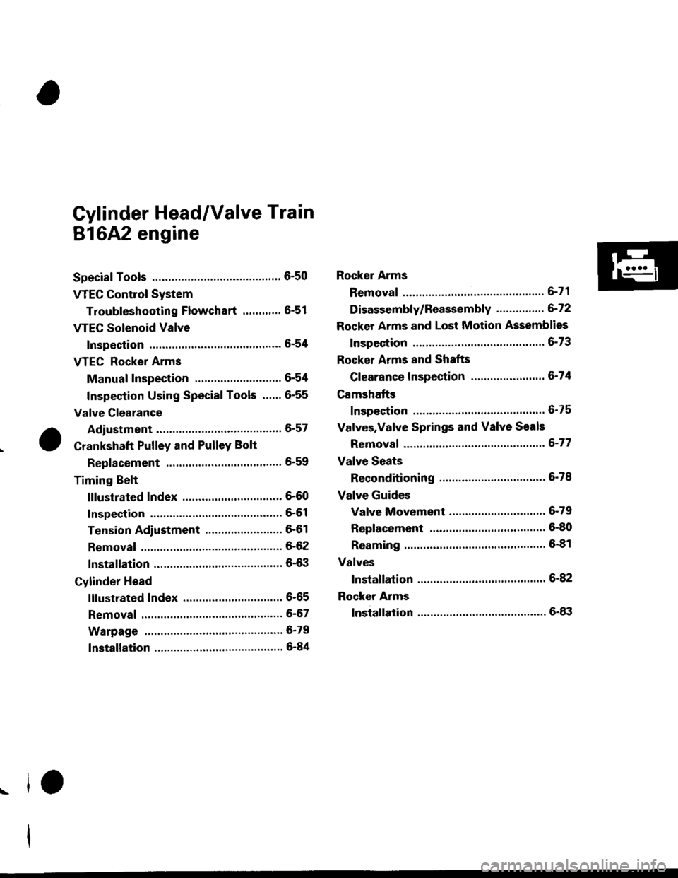
Gylinder Head/Valve Train
816A2 engine
Special Tools ............. 6'50 Rocker Arms
VTEC Contlol System
Troubfeshooting Flowchart ............ 6-51 Disassembly/Reassembly ...............6'72
VTEC Solenoid ValveRocker Arms and Lost Motion Assemblies
Inspection ...""'...... 5-54 Inspection .........""' 6-73
VTEC Rocker ArmsRocker Arms and Shafts
Manual Inspection ........................... 6-54 Clearance Inspection ..'..."'.............. 6-74
Inspection Using Special Tools .....' 6-55 Camshafts
Valve Clearance
.^ Adiustment .........." 6-57 Valves'Valve Springs and Valve Seals
. t Crankshaft Pulley and Pulley Bolt Removal """"""""' 6-77
Replacement ..".....6-59 Valve Seats
Timing BeltReconditioning ......6'78
Cylinder Headlnstallation '............ 6-82
Page 161 of 2189
VTEC Control SYstem
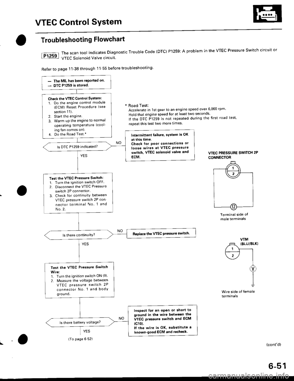
The scan tool indicates Diagnostic Trouble Code {DTC) Pl259:
VTEC Solenoid Valve circuit
Refer to page 1'l-38 through 11 55 before troubleshooting
Troubleshooting Flowchart
YES
A problem in the WEC Pressure Switch circuit or
* Road Test:Accelerate in 1st gear to an engine speed over 6,000 rp '
Hold that engine speed for at leasttwo seconos'
lf the DTC P1259 is not repeated during the first road test'
repeat this test two more times
VTEC PRESSURE SWITCH 2P
CONNECTOR
Terminalside ofmale termtnals
WM
/1 IBLU/BLKI
/ 1 Y------rt--------- l I
\1-/ |I
I
I1
Wire side of femaleterminals
(cont'd)
6-51
The MIL has been teported on.
DTC P1259 is siored.
Check the VTEC Control SYsiem:
1. Do the engine control module(ECM ) Reset Procedure (see
section 11).
2. Start the engine
3. Warm uP the engine to normal
operating temPerature (cool
ing fan comes on).
4. Do the Road Test.*lntermittent failure, sYstem is OK
at this time.Check for Poor connectlons or
loose wires at VTEC Pressureswilch. VTEC aolenoid valvo and
ECM.
ls DTC P1259 indicated?
Test the VTEC Pressure Switch:
1. Turn the ignition switch OFF.
2. Disconnect the VTEC Pressure
switch 2P connector.
3. Check for continuity between
VTEC pressure switch 2P con
nector telminal No 1 and
No.2.
Reolace the VTEC Pre3sure switch.
Test the VTEC Pressure Switch
Wire:1. Turn the ignition switch ON (ll).
2. N4easure the voltage between
VTEC press u re switch 2P
connector No. 1 and bodyground,
Inspect lor an open or short toground in the wire between the
VTEC orassure swilch and ECM
{c101.lf the wire i3 OK, substitute a
known-good ECM and recheck.
{To page 6 52)
Page 162 of 2189
VTEC Control System
Troubleshooting Flowchart (cont,d)
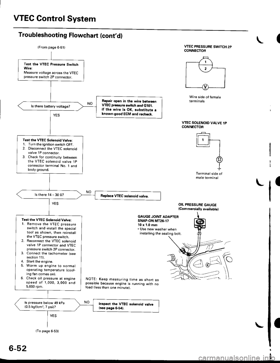
VTEC PRESSURE SWITCH 2PCONNECTOR
Wire side of temaleterminals
OIL PRESSURE GAUGE(Comm.rcially avail.bte)
GAUGE JOINT ADAPTERSNAP.ON MT26.1710 x 1.0 ftm. Use new washer wheninstalling the sealing bott.
NOTE: Keep measuring time as shorr aspossible because engine is running witn noload lless than one minute).
6-52
(
VTEC SOLENOID VALVE lPCONNECTOF
Ir------r I
lLl.ll-r
II
It
Terminal side ofmale terminal
I
(From page 6-5l l
(To page 6-53)
Test tha VTEC P.es3uro SwitchWi.e:Measure voltage across the VTECpressure switch 2P connector.
Ropair opon in the wiro batwoenVIEC pr...urc switch and G lot .lf the wiro is OK, 3ubltitutr aknown-good ECM and rochack.
ls there battery voltage?
Test the VTEC Solenoid V.tve:1. Turn the ignition switch OFF.2. Disconnect the VTEC solenoidvalve 1P connector.3. Check for continuity betweenthe VTEC solenoid valve 1Pconnector terminal No, I andbody ground.
ls there 14 - 30 O?
Te3t the VTEC Sotonoid Vatve:'1. Remove the VTEC pressureswitch and install the specialtool as shown. then reinstallthe VTEC pressure switch.2. Reconnect the VTEC solenoidvalve 1P connector and VTECpressure switch 2P connector,3. Connect the tachometer (seesection 1l).4. Start the engine.5. Warm up engine to normaloperatrng temperature (cool-ing fan comes on).6. Check oil pressure at enginespeed of 1,000,3,000 and5,000 rpm.
ls pressure below 49 kPa(0.5 kgflcm,,7 psi)?Inipoct thg VTEC aolenoid valvel3ee P8go 6-54).
I
Page 163 of 2189
(From page 6-52)
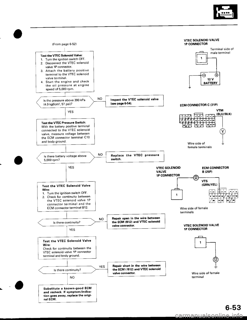
Test the VTEC Solenoid Valve:
1. Turn the ignition switch OFF
2. Disconnect the VTEC solenoid
valve 1P connector,
3. Attach the batterY Posrtrveterminal to the VTEC solenoid
valve terminal.4. Start the engine and check
the oil Pressure at engine
speed ol5,000 rPm
lrcoect the VTEC solenoid valve(see page S54)ls the pressure above 390 kPa(4.0 kgt/cm?, 57 Psi)?
Test the VTEC Pressure Switch:
With the battery Positive terminal
connected to the VTEC solenoid
valve, measure voltage between
the ECM connector terminal C10
and body ground.
ls there battery voltage above
5,000 rpm?
Test the VTEC Solenoid Valve
Wire:1. Turn the ignition switch OFF
2. Check for continuitv between
the VTEC solenoid valve 1P
con nector terminal and the
ECM connector terminal 812
Repair open in the wire between
the ECM lB12| and VTEC aolenoid
Test lhe VTEC Solenoid Valve
Wire:Check for continuity between the
VTEC solenoid valve'lP connector
terminal and body ground.
Repair short in the wiro b€'tween
the ECM ( 812) and VTEC aolenoid
Substitute a known'good ECM
and recheck. lI sYmptom/indica'tion goes away. repleca the origi-
nal ECM.
VTEC SOLENOID VALVE
1P CONNECTOR
Terminal side ofmale terminal
VIEC SOLENOIDVALVE1P CONNECIOR
ECM CONNECTORB l2sP)
ECM CONNECTOR C (31PI
WM
Wire side ot female
termrnals
VTEC SOLENOID VALVE
1P CONNECTOR
I'ft
I
I
Wire side of female
termanal
6-53
Page 164 of 2189
VTEC Solenoid ValveVTEC Rocker Arms
a
I
(
Inspection
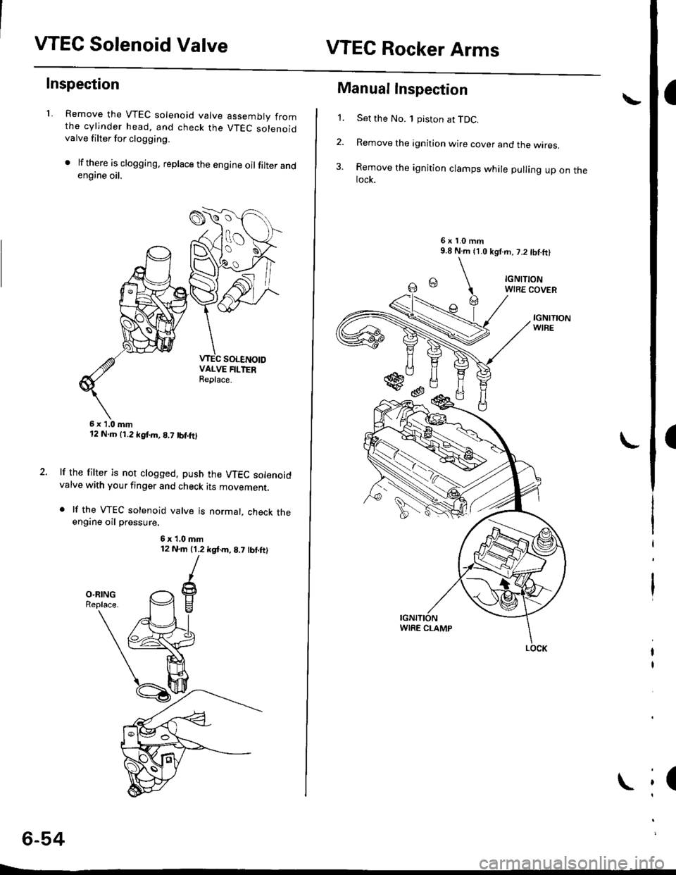
1. Remove the VTEC solenoid valve assembly fromthe cylinder head. and check the VTEC solenoidvalve filter for clogging.
. lf there is clogging, replace the engine oilfilter andengine oil.
6x1.0mm12 N.m (1.2 kgf.m, B,7 tbf.ftl
lf the filter is not clogged. push the VTEC solenoidvalve with your finger and check its movemenr.
. lf the VTEC solenoid valve is normal, check theengine oil pressure.
6x1.0mm12 N.m (1.2 kgtm,8.7 lbt.ft)
6-54
L-
SOLENOID
Manual Inspection
1. Set the No. 1 piston at TDC.
2. Remove the ignition wire cover and the wires.
3. Remove the ignition clamps while pulling up on theIock.
6xl.0mm9.8 N.m (1.0 kgl.m, 7.2 tbtftl
IGNITIONWIRE COVER
IGNITIONWIRE
\
LOCK
Page 171 of 2189
Inspection
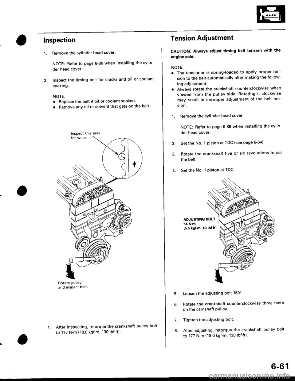
Remove the cylinder head cover.
NOTE: Refer to page 6-86 when installing the cylin-
der head cover.
Inspect the timing belt for cracks and oil or coolant
soakrng.
NOTE:
. Replace the belt if oil or coola nt soaked.
. Remove any oil or solvent that gets on the belt'
I
Rotate PUlleYand inspect belt-
After inspecting, retorque the crankshaft pul
to 177 N.m (18.0 kgf'm, 130 lbf'ft)
'L
lnspect thrs area
Tension Adiustment
CAUTION: Always adiust timing belt tension with the
engine cold.
NOTE:
. The tensioner is spring-loaded to apply proper ten
sion to the belt automatically after making the follow-
ing adjustment.
. Always rotate the crankshaft counterclockwise when
viewed from the pulley side. Rotating it clockw'se
may result in improper adjustment of the belt ten-
sion.
1, Remove the cylinder head cover.
NOTE; Refer to page 6-86 when installing the cylin-
der head cover.
2. Set the No. 1 piston at TDC (see page 6-64)
3. Rotate the crankshaft live or six revolutions to set
the belt.
4. Set the No. 1 Piston at TDC
ADJUSTING BOLT
54 N.m(5.5 kgt.m, a0 lbtftl
5.
7.
8.
Loosen the adjusting bolt 180'.
Rotate the crankshaft counterclockwise three teeth
on the camshaft PulleY.
Tighten the adjusting bolt.
After adjusting, retorque the crankshaft pulley bolt
to 177 N.m (18.0 kgf'm, 130 lbnft)
ley bolt
6-61
Page 172 of 2189
Timing Belt
Removal
NOTE:
. Replace the timing belt at 105,000 mites (168,000 km)according to the maintenance schedule (normal con-ditions/severe conditions).
lf the vehicle is regularly driven in one or more of thefollowing conditions, replace the timing belt at 60,OOOmiles (U.S.A.) 100,000 km {Canada).. In very high temperatures (over 110"F, 43"C).. In very low temperatures (under -20.F, 29.C).. Turn the crankshaft pulley so the No. 1 piston is attop dead center (TDC) before removing the belt (seepage 6-57).
. Inspect the water pump before installing the timingbelt {see page 10-14).
1.
IOLER PULLEY BRACKETEOLT10 x 1.25 mm44 N.m 14.5 kgf.m, 33 bnft)
6-62
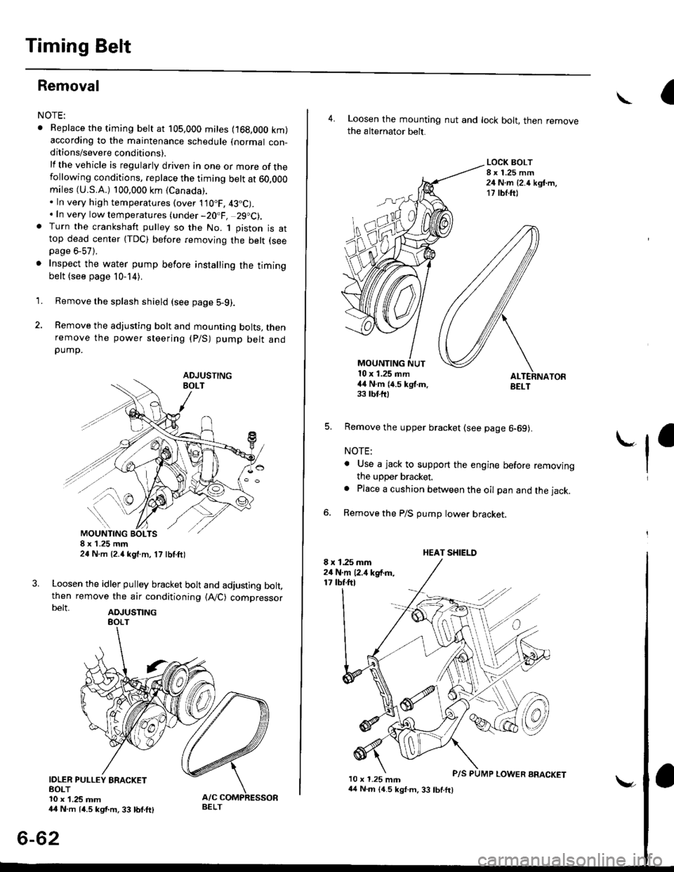
Remove the splash shield (see page 5-9).
Remove the adjusting bolt and mounting bolts, thenremove the power steering (P/S) pump belt andpump.
8xL25mm24 N m {2.{ kgf.m, 17 lbf.ft)
Loosen the idler pulley bracket bolt and adjusting bolt,then remove the air conditioning (A,/C) compressorbelt aDJUsnNG
44 N.m 14.5 kgt.m, 33 lbf.ft)
P/S PUMP LOWER ARACKET
a\
4. Loosen the mounting nut and lock bolt, then removethe alternator belt.
LOCK BOLT8 x 1.25 mm24 N.m {2.4 kgt.m.17 rb{.ftl
5. Remove the upper bracket (see page 6-69).
NOTE:
. Use a jack to support the engine before removingthe upper bracket.
o Place a cushion between the oil pan and the jack.
Remove the P/S pump lower bracket
8 x 1.25 mm24 N.m 12.,1 kgf.m,17 tbf.ftl
l0 x 1.25 mm
'-f'
MOUNTING10 x 1.25 mm44 N.m (4.5 kgf.m.33 rbf.fttBELT
HEAT SHIELD
Page 175 of 2189
Cylinder Head
lllustrated Index
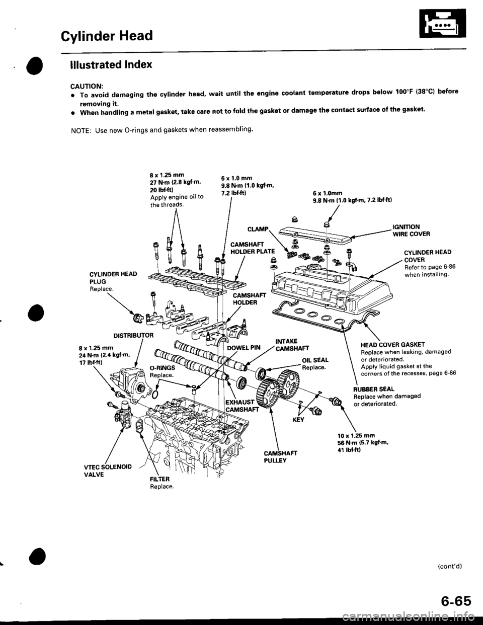
CAUTION:
. To avoid damaging the cylinder head, wait until the engine coolant tempsraturo drops below 100"F (38"C1 bofote
removing it,
. when handling a metal gasket, take caro not to fold the gaskot or damage the contact surface of the gasket.
NOTE: Use new O-rings and gaskets when reassembling.
CYLINDER HEAO
PLUGReplace.
)@
DISTRIBUTOR
8 x 1 ,25 mm
27 N.m P.E kgl m.
20 tbf.foApply engine oil to
the threads.
cr.rMp.S
CAMSHAFT A"o''*t*'; wes@
OIL SEALReplace.
6 x l,omm9.8 N'm tl.0 kgt'm,7.2lbf ft)
RUBBER SEALReplace when damaged
or detedorated.
6x1.0mm9.8 N.m (1.0 kgf'm,
7.2 rbnftl
fi%
IGNMONWIRE COVER
CYLINOER HEAD
COVERRefer to page 6-86
when installing
HEAD COVER GASKETReplace when leaking, damaged
or deteriorated.Apply liquid gasket at thecorners of the recesses, Page 6-86
8 x 1,25 mm24 N.m {2.4 kgf'm,
1? tbf.ftl
EXHAUST
10 x 1.25 mm56 N.m (5.7 kgf m,,r1 lbl.ft)
(cont'd)
6-65
Page 176 of 2189
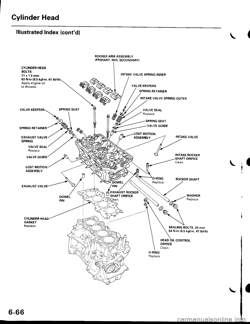
Cylinder Head
lllustrated Index (cont'dl
CYLINDER HEADBOLTS11 x 1.5 mm83 N.m {8.5 kg{.m, 61Apply engine oilto threads.
INTAKE VALVE SPRING INNER
VALVE KEEPERS
SPRING RETAINER
INTAKE VAI.VE SPRING OUTER
valvEKEEPEBS\:""j"*'
SPRING RETAINER
EXHAUST VALVESPRING
VALVE SEALReplace.
VALVE
LOST MOTIONASSEMBLY
EXHAUST VAL
VALVE SEALReplace.
SPRING SEAT
VALVE GUIDE
INTAKE VALVE
ROCKER SHAFT
SEALING AOLTS.20 mm64 N.m (6.5 kgt.m, 47 tbf.ft)
t
il
HEAO OIL CONTROLORIFICEClea n.
a
6-66
Page 177 of 2189
Removal
Engine removal is not required for this procedure.
!@@ Make sure jacks and safety stands are placed
properly and hoist brackels are attached to correst posi-
tion on the engine,
CAUTION:
o Use fender covers to avoid damaging painted sur-
faces.
To avoid damage, unplug the wiling connectors
carelully while holding the connector portion.
To avoid damaging the cylinder head, wait until the
engine coolant temperature drops below 100"F {38'Cl
before loosening the retaining bolt.
NOTE:
. Unspecified items are common.
. Mark all wiring and hoses to avoid misconnection.
AIso, be sure that they do not contact other wiring or
hoses or interfere with other parts.
o Inspect the timing belt before removing the cylinder
n eao.
. Turn the crankshaft pulley so that the No. 1 piston is
at top dead center (see page 6-64).
1. Disconnect the negative terminal from the battery.
Drain the engine coolant {see page 10-7).
. Remove the radiator cap to speed draining.
Remove the strut brace (see page 5-2).
Remove the intake air duct and air cleaner housing
(see page 5-3).
Remove the adjusting bolt and mounting bolt, then
remove the power steering (P/S) pump belt and pump
(see page 5 5).
2.
3.
4.
\
ADJUSTING
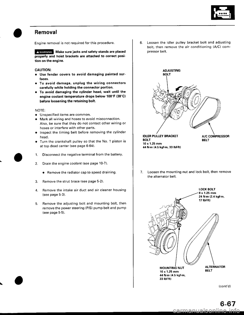
6. Loosen the idler pulley bracket bolt and adjusting
bolt, then remove the air conditioning (A/C) com-
pressor belt.
IDLER PULLEY BRACKETBOLT10 x 1.25 mm44 N.m {4.5 kg,l.m, 33 lbt.ft}
7. Loosen the mounting nut and lock bolt, then remove
the alternator belt.
LOCK BOLT8 x 1.25 mm24 N.m {2.4 kgf.m,17 tbtftl
ALTERNATORBELT10 x 1.25 mm,l,l N.m {4.5 kgf.m,33 tbf.ft,
(cont'd)
6-67