HONDA CIVIC 1999 6.G Workshop Manual
Manufacturer: HONDA, Model Year: 1999, Model line: CIVIC, Model: HONDA CIVIC 1999 6.GPages: 2189, PDF Size: 69.39 MB
Page 1191 of 2189
t-
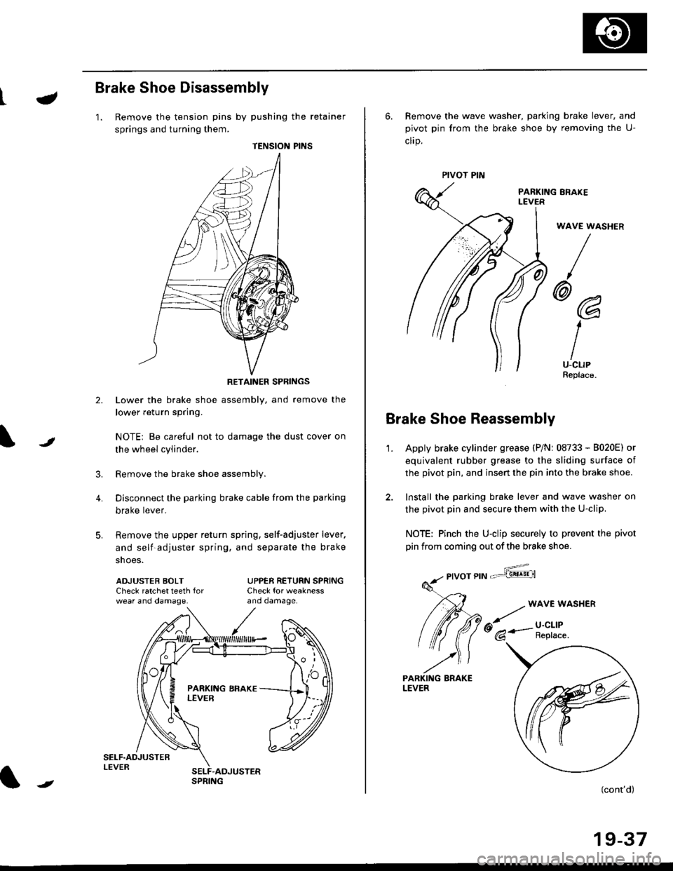
Brake Shoe Disassembly
1. Remove the tension pins by pushing the retainer
springs and turning them.
TENSION PINS
RETAINER SPRINGS
Lower the brake shoe assembly, and remove the
lower return spring.
NOTEi Be careful not to damage the dust cover on
the wheel cylinder.
Remove the brake shoe assembly.
Disconnect the parking brake cable from the parking
brake lever.
Remove the upper return spring, self-adjuster lever,
and self-adjuster spring, and separate the brake
snoe5.
t
3.
4.
ADJUSTEB BOLTCheck ratchet teeth forwear ano oamage.
UPPER RETURN SPRINGCheck for weaknessano oamage.
ll
,'/
N
r
//
t
6. Remove the wave washer, parking brake lever, and
pivot pin from the brake shoe by removing the U-
clrp.
PARKING ERAKEI-EVER
WAVE WASHER
/
@@
I
IU-CLIPReplace.
Brake Shoe Reassembly
1.Apply brake cylinder grease (P/Nr 08733 - B020E) or
equivalent rubber grease to the sliding surface of
the pivot pin, and insert the pin into the brake shoe.
Install the parking brake lever and wave washer on
the pivot pin and secure them with the U-clip,
NOTE: Pinch the U-clip securely to prevent the pivot
pin from coming out of the brake shoe.
,6;::"'
(cont'd)
19-37
LEVER
Page 1192 of 2189
Rear Drum Brake
Brake Shoe Reassembly {cont'dl
Connect the parking brake cable to the parking
brake lever.
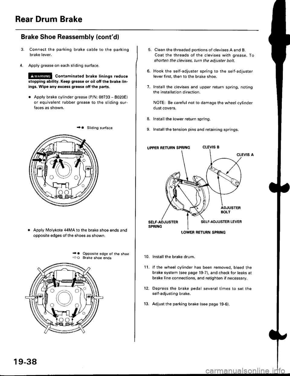
Apply grease on each sliding surface.
!@ contaminated brake linings reduce
stopping ability. Keep grease or oil off the blake lin-
ings. Wipe any excess grease off the parts,
. Apply brake cylinder grease {P/N: 08733 - 8020E)
or equivalent rubber grease to the sliding sur-
faces as shown.
+a Sliding surlace
Apply Molykote 44MA to the brake shoe ends and
opposite edges ofthe shoes as shown.
_' o Opposite edge of the shoe+O Brake shoe ends
19-38
13.
5. Clean the threaded portions of clevises A and B.
Coat the threads of the clevises with grease. To
shoften the clevises, tun the adjuster bolt.
6. Hook the self-adjuster spring to the self-adjuster
lever first, then to the brake shoe
7. Install the clevises and upper return spring. noting
the installation direction.
NOTE: Be careful not to damage the wheel cylinder
dust covers,
8. Install the lower return spring.
9. Install the tension pins and retaining springs.
uppER RETURT{ SpRtNG CLEVIS B
CLEVIS A
Installthe brake drum.
lf the wheel cylinder has been removed, bleed the
brake system (see page 19-7), and check for leaks at
brake line connections, and retighten if necessary.
Depress the brake pedal several times to set the
self-adjusting brake.
Adjust the parking brake (see page 19-6).
't0.
11.
12.
LOWER RETURN SPRING
Page 1193 of 2189
Brake Hoses/Lines
LJ
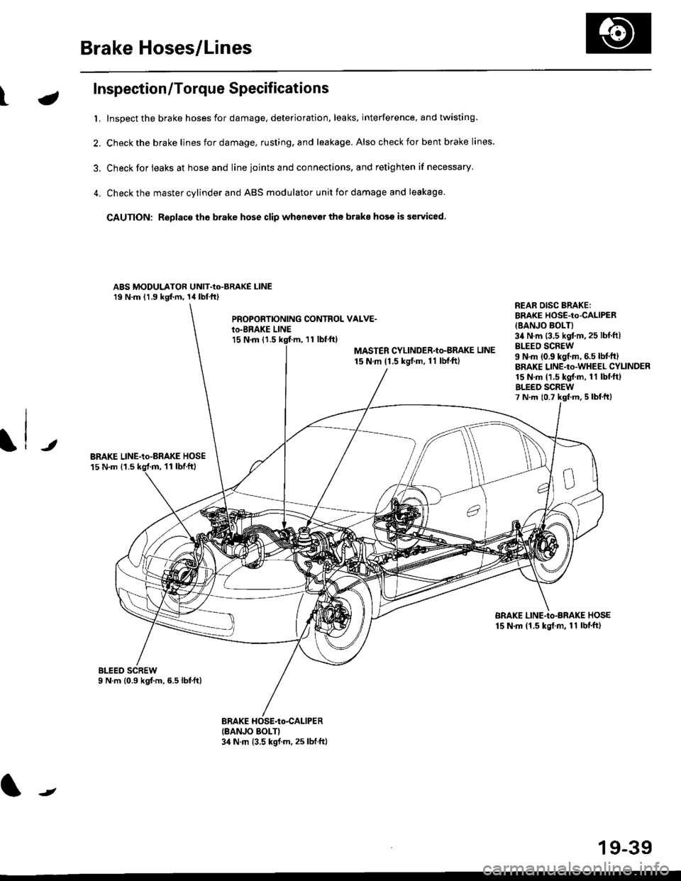
Inspection/Torque Specifications
t. Inspect the brake hoses for damage, deterioration, leaks, interference, and twisting.
2. Check the brake lines for damage, rusting. and leakage. Also check for bent brake lines.
3. Check for ieaks at hose and line ioints and connections, and retighten if necessary'
4. Check the master cylinder and ABS modulator unit for damage and leakage
CAUTION: Replace tho brake hose clip whenev€r the brake hose is serviced.
ABS MODULATOR UNIT-Io-BRAKE l-lNE19 N.m (1.9 kgf.m, 14lbl.ftl
PROPOBTIONING CONTROL VALVE.io-BRAKE LINEl5 N.m (1.511 tbf.ftl
MASTER CYLINDER-Io-BMKE LINE
15 N.m (1.5 ksrf.m, 11 lbf'ft)
REAR DISG BRAKE:BRAKE HOSE-to4ALlPER
{BANJO BOLT}34 N.m (3.5 kgtm,25 lbf ftlBLEEO SCREW9 N'm (0.9 kgf.m, 6.5 lM.ftlBRAKE LINE-to-WHEEL CYLINDER15 N.m (1.5 kgl.m, 11 lbf.ftlBLEED SCREW7 N.m {0.7 kst m, 5 lbf,ttl
JBRAKE LINE-io-aRAKE HOSE15 N.m {1.511 tbtft)
BRAKE LINE-Io-BRAKE HOSE15 N.m (1.5 kgt.m, 11 lbf'ft)
(BANJO BOLT}3,1 N.m 13.5 kgf.m, 25 lbf.ft)
J
19-39
Page 1194 of 2189
Brake Hoses/Lines
Hose Replacement
CAUTION:
. Bgfore reagsembling, chgck that all parts are free of
dust and othor foroign particles.
. Repl8ce parts with new ones whenever specified to
do so,
. Do not spill brake fluid on th6 vehicle; it may damage
tho paint; if brake fluid does contact the paint, wash
it off immediately with water.
1.Replace the brake hose if the hose is twisted, cracked,
or if it leaks.
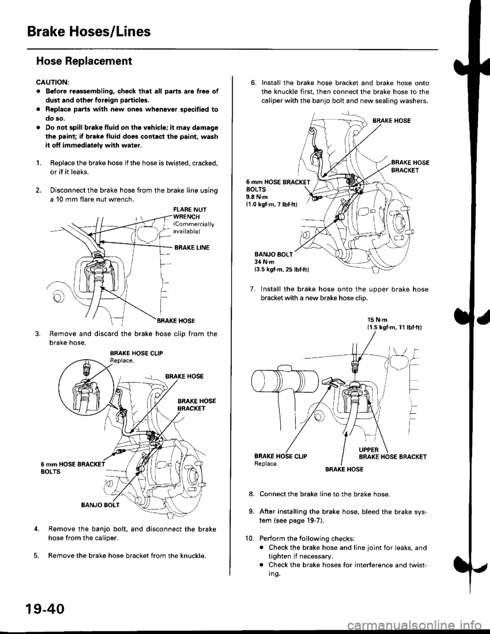
Disconnect the brake hose from the brake line using
a 10 mm flare nut wrench.
FLARE NUTWRENCHlCommerciallyava ilable)
BRAKE LINE
BRAKE HOSE
Remove and discard the brake hose cliD from the
brake hose.
Remove the banjo bolt, and disconnect the brake
hose from the caliper.
Remove the brake hose bracket from the knuckle.
19-40
10.
6. Install the brake hose bracket and brake hose onto
the knuckle first. then connect the brake hose to the
caliper with the banjo bolt and new sealing washers.
BRAKE HOSE
6 mm HOSE BRACKETBOLTS9.8 N.m{1.0 kgf m, 7 lbtfr}
BANJO BOI.T34 N.m{3.5 kgf.m,25 lbt.ftl
7. Install the brake hose onto the uooer brake hose
bracket with a new brake hose clip
15 N.m(1.s ks{.m, 11 lbl.ftl
Connect the brake line to the brake hose.
After installing the brake hose, bleed the brake sys-
tem (see page 19-7).
Perform the following checks:
. Check the brake hose and line joint for leaks, and
tighten if necessary.
. Check the brake hoses for interference and twist-
I ng.
8.
Page 1195 of 2189
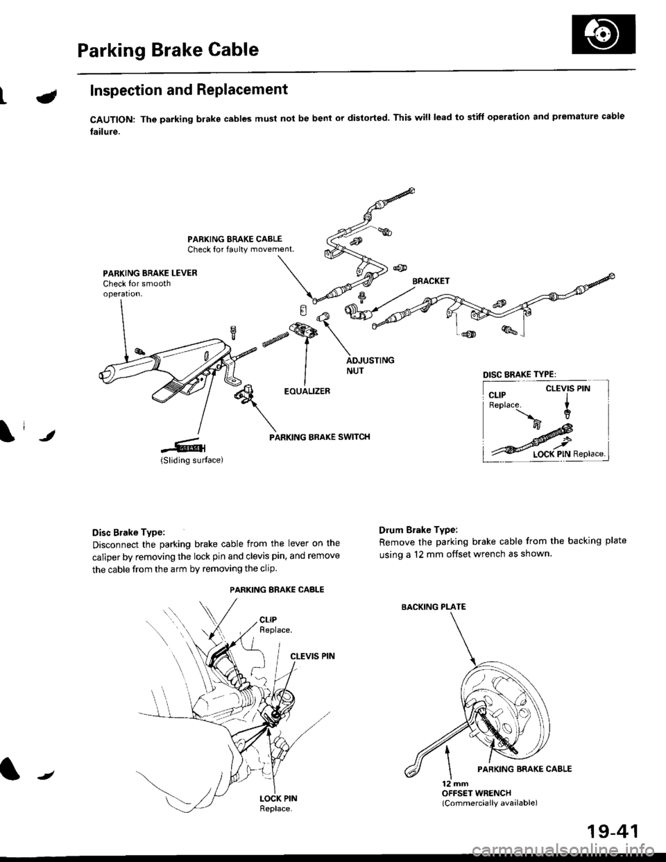
Parking Brake Cable
LInspection and Replacement
CAUTION: The parking blake cables must not be bent or distorted. This will lead to stiff operation and premature cable
failure.
PARKING BRAKE CABLECheck for faulty movement.
PARKING BRAKE LEVERCheck for smoothoperation.
\i ,
EOUALIZER
PARKING BRAKE SWITCH
Disc Brake Type:
Disconnect the parking brake cable from the lever on the
caliper by removing the lock pin and clevis pin, and remove
the cable from the arm by removing the clip
CLEVIS PIN
Drum Brake Type:
Remove the parking brake cable from the backing plate
using a 12 mm offset wrench as shown.
12 mmOFFSET WRENCH(Commercially available)
DISC BRAKE TYPE:
CLEVIS PIN
PARKING ERAKE CABLE
{tt
BACKING PLATE
/
19-41
Page 1196 of 2189
L-
t
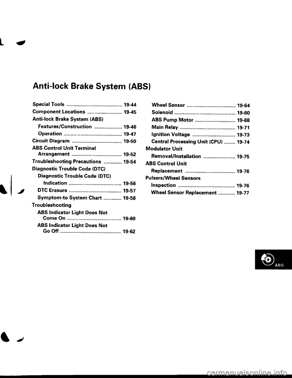
Anti-lock Brake System (ABSI
Special Tools ............. 19-44
Component Locations ......................... 19-45
Anti-lock Brake System (ABS)
Features/Construction ..................., 19-46
Operation ............... 19-47
Circuit Diagram ......... 19-50
ABS Control Unit Terminal
Arrangement ......... 19-52
Troubleshooting Precautions ............. 19-54
Diagnostic Trouble Code (DTCI
Diagnostic Trouble Gode (DTCI
Indication ........... 19-56
DTC Erasure ........... 19-57
Symptom-to System Chart ............. 19-58
Troubleshooting
ABS Indicator Light Does Not
Come On ............ 19-60
ABS Indicator Light Does Not
Go Off ............................................ 19-62
Wheel Sensor ........ 19-64
Solenoid ................. 19-60
ABS Pump Motor ............................. 19-68
Main Relay ............. 19-71
lgnition Voltage .... 19-73
Central Processing Unit {CPU} ........ 19-74
Modulator Unit
Removal/lnstallation ....................... 19-75
ABS Control Unit
Replacement ......... 19-76
Pulsers/Wheel Sensors
Inspection .............. 19-76
Wheel Sensor Replacement ............ 19-77
t/
Page 1197 of 2189
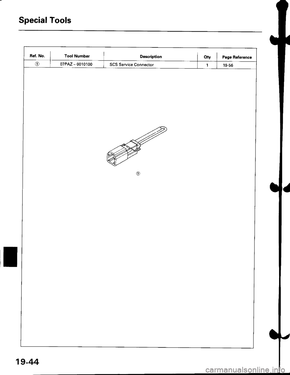
Special Tools
Ret. No. I Tool Number I Description I O,V I page Reference
(!) I 07PM- 0010100 I SCS Service Connector t I 19_s6
19-44
Page 1198 of 2189
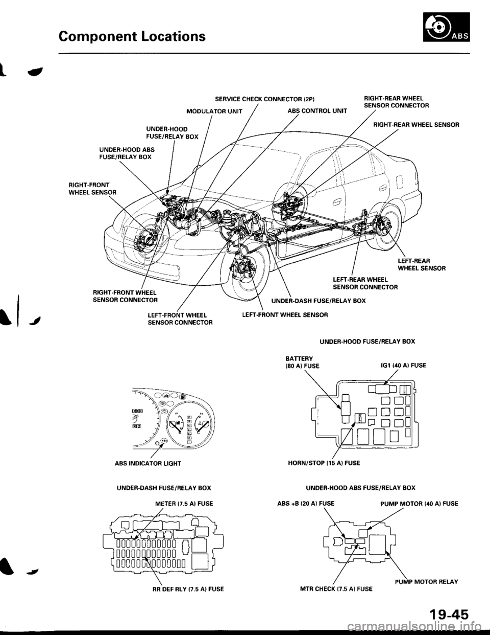
Component Locations
ta
SERVICE CHECK CONNECTOR {2PIBIGHT.REAR WHEELSENSOR CONNECTORMOOULATOR UNITABS CONTROL UNIT
RIGHT-REAR WHEEL SENSOR
LEFT.R€AR WHEELSENSOR CONNECTOR
J
UNDER.DASH FUSE/RELAY 8OX
LEFT.FRONT WHEEL SENSOR
ABS +B (20 A) FUSE
UNDER.HOOD FUSE/RELAY BOX
lcl lilo Al FUSE
ABS INDICATOR LIGHT
UNOEF.DASI{ FUSE/RELAY BOX
HORN/STOP I15 A) FUSE
UNDER.HOOO ABS FUSE/RELAY BOX
PUMP MOTOR {'O A} FUSE
PUMP MOTOR BELAY
E
o
METEB I7.5 AI FUSE
0
0
0
00000 n
00000 u
BR DEF RLY 17,5 A) FUSE
t
MTR CHECK (7.5 AI FUSE
19-45
Page 1199 of 2189
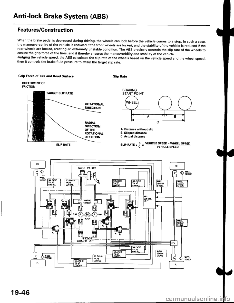
Anti-lock Brake System (ABSI
Featu res/Construction
When the brake pedal is depressed during driving, the wheels can lock before the vehicle comes to a stop, In such a case,the maneuverability of the vehicle is reduced if the front wheels are locked, and the stability of the vehicle is reduced if therear wheels are locked, creating an extremely unstable condition. The ABS precisely controls the slip rate of the wheels toensure the grip force of the tires. and it thereby ensures the maneuverbility and stability of the vehicle.Judging the vehicle speed. the ABS calculates the slip rate of the wheels based on the vehicle speed and the wheel speed,then it controls the brake fluid pressure to attain the target slip rate.
Grip Force of Tire and Road Surlace
COEFFICIENT OFFRICTION
TARGET SLIP RATE
Slip Rate
BRAKINGSTART POINT
ROTATIONALDIRECTION
RADIALDIRECTIONOF THEROTATIONALOIRECTION
A: Distance without slio8: Slippsd distanceC: Actuel distance
sr-rrmre=f=SLIP RATEVEIIICLE SPEED - WHEEL SPEEOVEHICLE SPEED
19-46
Page 1200 of 2189
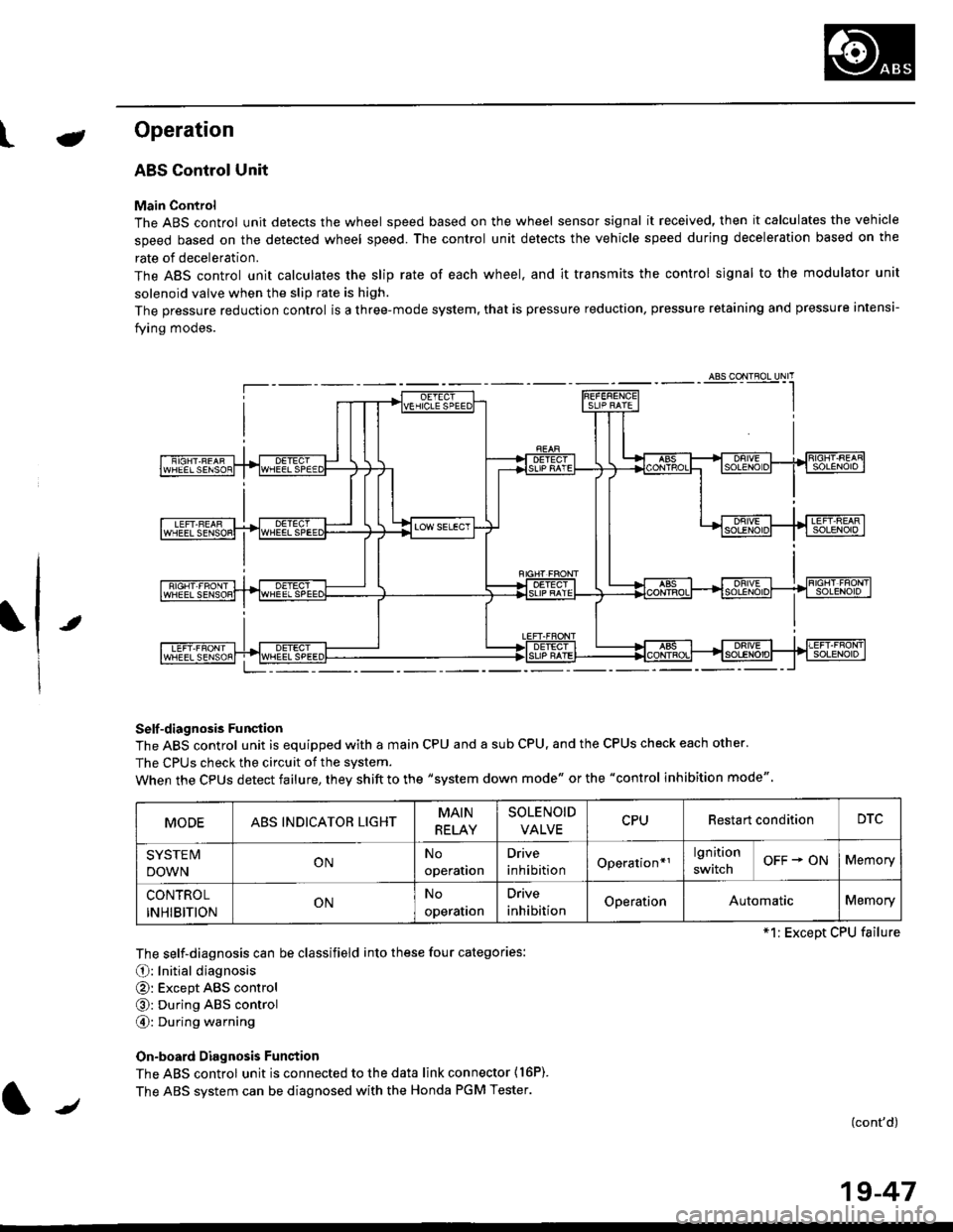
t-Operation
t
ABS Control Unit
Main Control
The ABS control unit detects the wheel speed based on the wheel sensor signal it received, then it calculates the vehicle
speed based on the detected wheel speed. The control unit detects the vehicle speed during deceleration based on the
rate of deceleration.
The ABS control unit calculates the slip rate of each wheel. and it transmits the control signal to the modulator unit
solenoid valve when the slip rate is high.
The pressure reduction control is a three-mode system, that is pressure reduction, pressure retaining and pressure intensi-
fying modes.
Self -diagnosis Funqtion
The ABS control unit is equipped with a main CPU and a sub CPU, and the CPUS check each other'
The CPUs check the circuit of the svstem.
When the CPUS detect failure, they shift to the "system down mode" or the "control inhibition mode"
The self-diagnosis can be classifield into these four categories:
O: Initial diagnosis
@: Except ABS control
@: During ABS control
@: During warning
On-board Diagnosis Funstion
The ABS control unit is connected to the data link connector {16P).
The ABS system can be diagnosed with the Honda PGM Tester.
(cont'd)
MODEABS INDICATOR LIGHTMAIN
RELAY
SOLENOID
VALVECPURestart conditionDTC
SYSTE IV
DOWNONNo
operation
Drive
inhibitionOperation*rlgnition
switchOFF + ONMemory
CONTROL
INHIBITIONONNo
operalron
Drive
inhibitionOperationAutomaticMemory
*1: Except CPU failure
/
19-47