HONDA CIVIC 1999 6.G Workshop Manual
Manufacturer: HONDA, Model Year: 1999, Model line: CIVIC, Model: HONDA CIVIC 1999 6.GPages: 2189, PDF Size: 69.39 MB
Page 1251 of 2189
b
GLASS
REGULATOR
+"+
J\
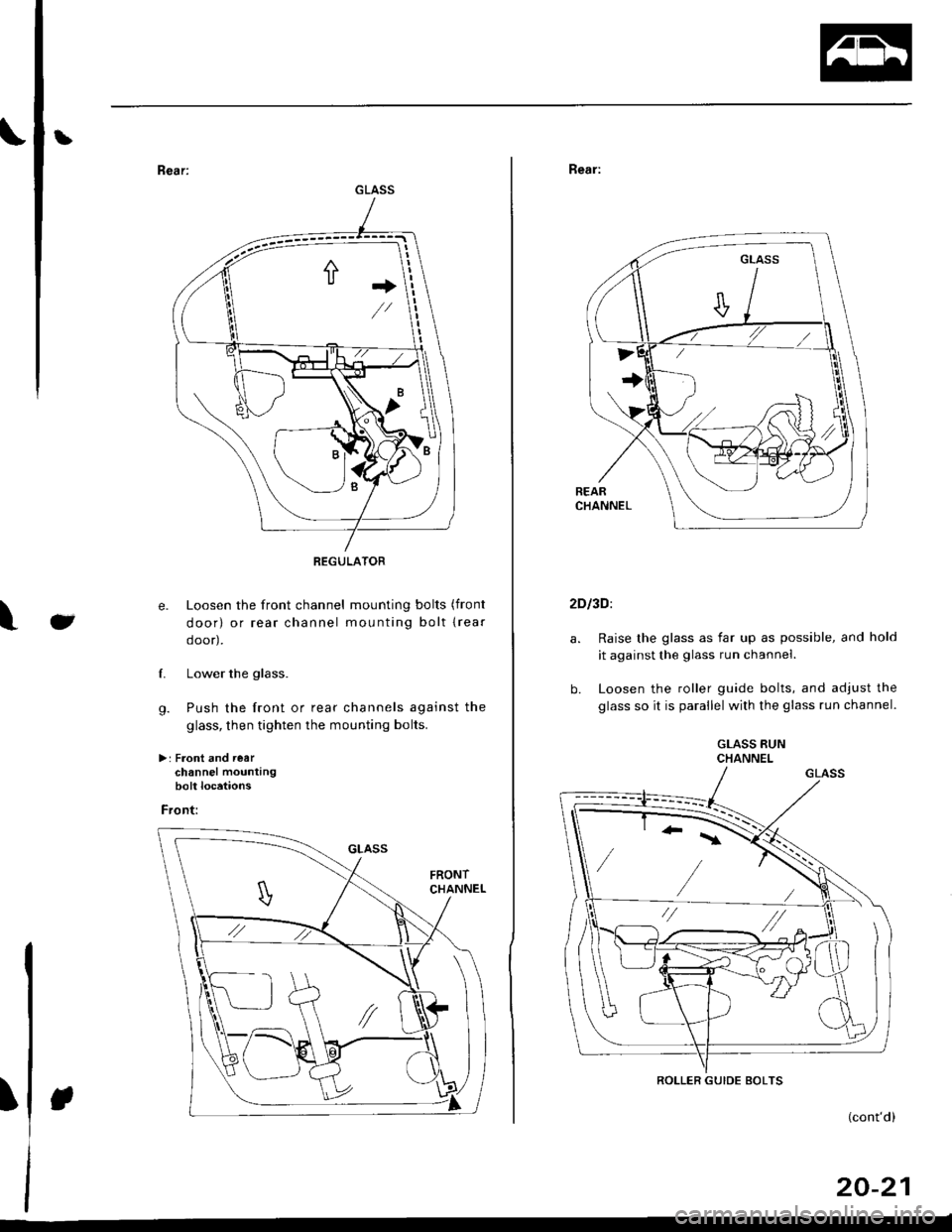
e. Loosen the front channel mounting bolts (front
door) or rear channel mounting bolt lrear
ooor,,
f. Lower the glass.
g. Push the front or rear channels against the
glass, then tighten the mounting bolts.
>: Front and rearchannel mountingbolt locations
Front:
\
Rear:
2DI3D:
b.
Raise the glass as far up as possible, and hold
it against the glass run channel.
Loosen the roller guide bolts, and adjust the
glass so it is parallel with the glass run channel.
GLASS RUNCHANNEL
ROLLER GUIDE BOLTS
(cont'd)
20-21
Page 1252 of 2189
Doors
Glass Adjustment {cont'd)
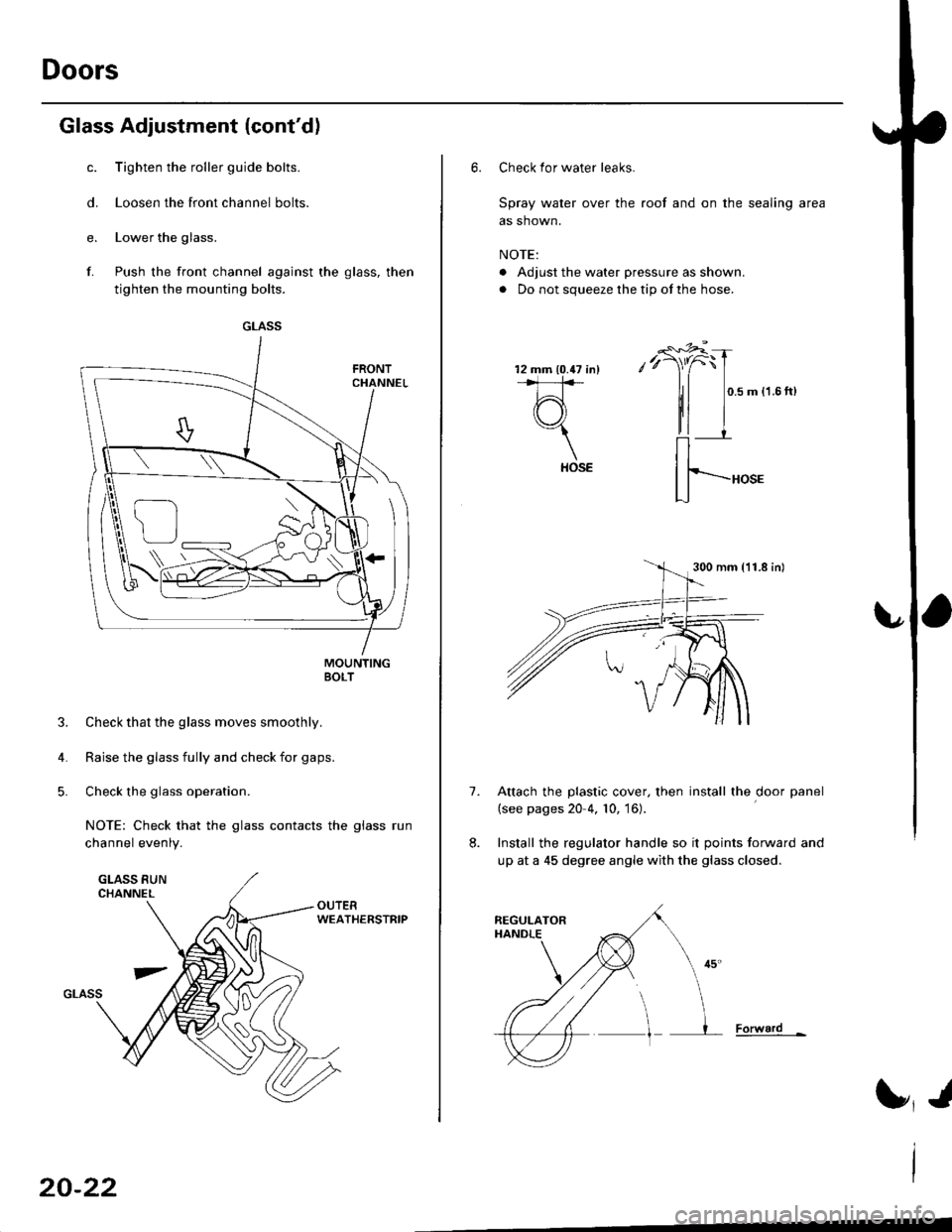
c. Tighten the roller guide bolts.
d. Loosen the front channel bolts.
e. Lower the glass.
f. Push the front channel against the glass, then
tighten the mounting bolts.
MOUNTINGBOLT
3. Check that the glass moves smoothly.
4. Raise the glass fully and check for gaps.
5. Check the glass operation.
NOTE: Check that the glass contacts the glass run
channel evenly.
WEATHERSTRIP
GLASS
U
-\,
20-22
6. Check for water leaks.
Spray water over the roof and on the sealing area
as shown.
NOTE:
. Adjust the water pressure as shown.
. Do not squeeze the tip of the hose.
0.5 m {1.6ft)
HOSE
Attach the plastic cover, then install the door panel
(see pages 20 4, 10, 16).
Install the regulator handle so it points forward and
up at a 45 degree angle with the glass closed.
Forward -
1.
HOSE
300 mm {11.8 in)
Page 1253 of 2189
bPosition Adjustment
NOTE: Place the vehicle on a firm, level surface when
adjusting the doors.
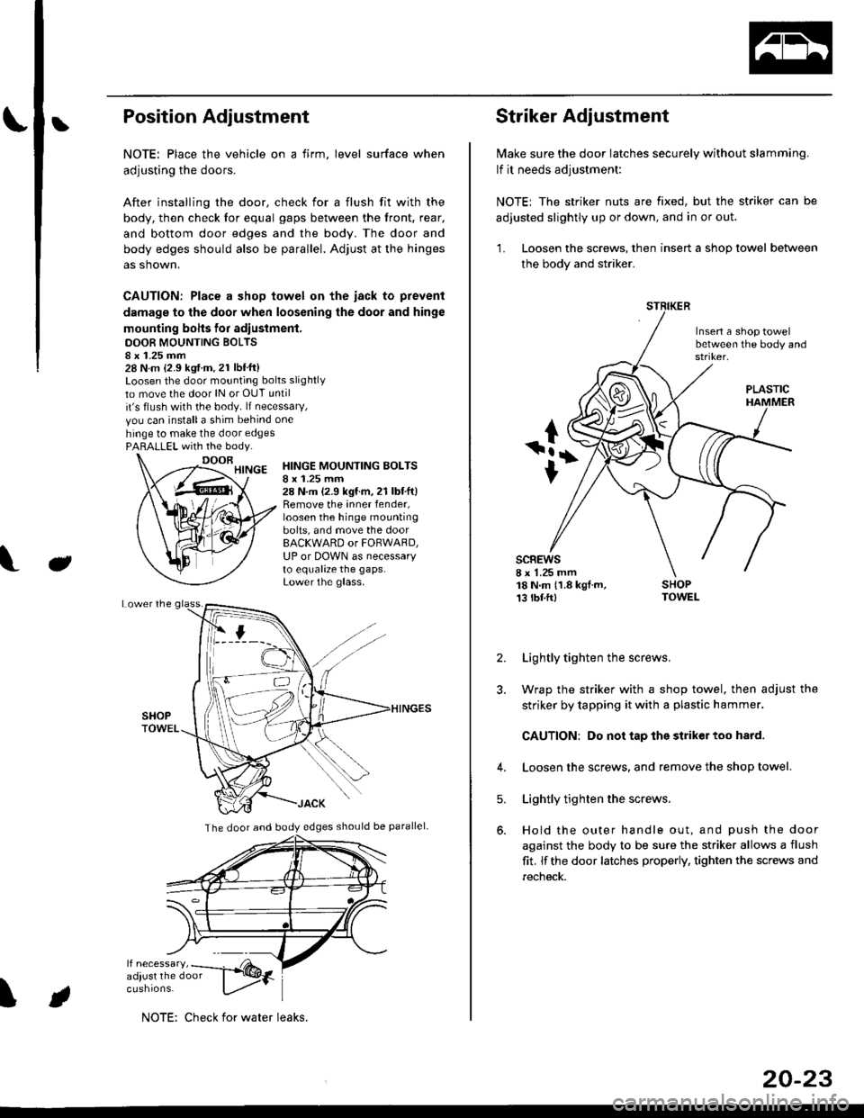
After installing the door, check for a flush fit with the
body, then check for equal gaps between the front, rear,
and bottom door edges and the body. The door and
body edges should also be parallel. Adjust at the hinges
as shown,
CAUTION: Place a shop towel on the iack to prevent
damage to the door when loosening the door and hinge
mounting bohs for adiustment.
DOOR MOUNTING BOLTS8 x 1.25 mm28 N.m {2.9 kgf.m.21 lbt'ft}Loosen the door mounting bolts slightly
to move the door lN or OUT until
it's flush with the body. lf necessary,
vou can installa shim behind one
hinge to make the door edgesPARALLEL with the body.
J
HINGE MOUNTING BOLTSI x 1.25 mm28 N.m (2.9 kgf.m,21 lbtft)Remove the inner fender,loosen the hinge mountingbolts, and move the doorBACKWARD or FORWARD,UP or DOWN as necessaryto equalize the gaps.Lower the glass.
\
The door and body edges should be parallel-
ifF t
NOTE: Check for water leaks.
20-23
Striker Adjustment
lvlake sure the door latches securely without slamming.
lf it needs adjustment:
NOTE; The striker nuts are fixed, but the striker can be
adjusted slightly up or down, and in or out.
'L Loosen the screws, then insert a shop towel between
the body and striker.
Insert a shop towelbetween the body and
sc8Ews8 x 1.25 mm18 N.m (1.8 kgf.m,13 tbtftl
PLASTIC
2. Lightly tighten the screws.
3. Wrap the striker with a shop towel, then adjust the
striker by tapping it with a plastic hammer.
CAUTION: Do not tap the striker too hard.
4. Loosen the screws. and remove the shop towel.
Lightly tighten the screws.
Hold the outer handle out, and push the door
against the body to be sure the striker allows a flush
fit. lf the door latches properly, tighten the screws and
recheck.
5.
Page 1254 of 2189
Mirrors
Mirror Replacement
NOTE: Take care not to scratch the mirror. mirror basecover and door.
l� Lower the door glass.
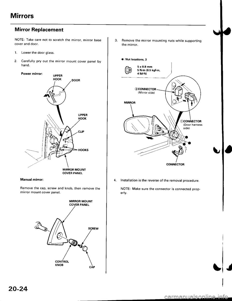
2. Carelully pry out the mirror mount cover panel bynano.
Power mirro.:
MIRROR MOUNTCOVEB PANEL
Manual mirror:
Remove the cap, screw and knob, then remove themirror mount cover panel.
MIRROR MOUNT
KNOB
20-24
3. Remove the mirror mounting nuts while supporting
the mirror.
a: Nut locations,3
€)CONNECTOR(Nrirror side)
MIRROR
(Door harnessside)
CONNECTOR
Installation is the reverse of the removal procedure.
NOTE: Make sure the connector is connected prop-
erly.
Page 1255 of 2189
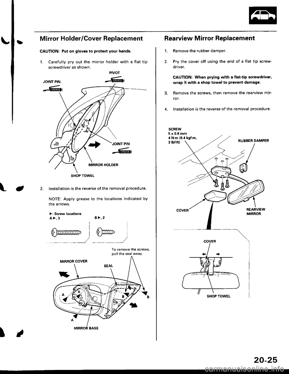
|}Mirror Holder/Cover Replacement
CAUTION: Put on gloves to protecl your hands.
L Carefully pry out the mirror holder with a flat tip
screwdriver as shown.
Installation is the reverse of the removal procedure.
NOTE: Apply grease to the locations indicated by
the arrows.
>: Sc.ew locationsA >, 3 s>,2
I
ry
To remove the screws,pull the seal away.
PIVOT
-6rJOINT PIN
-G{
J
6)drD
)
I
SHOP TOWEL
Rearview Mirror Replacement
1. Remove the rubber damper.
2. Pry the cover off using the end of a flat tip screw-
drivef.
CAUTION: When prying with a flat-tip screwdriver,
wrap it with a shop towel to prgvant damage.
3. Remove the screws, then remove the rearview mir-
ror,
4. Installation is the reverse of the removal procedure.
SCREW5x0.8mmil N.m lo.a kgf.m,3 lbf.ftl
SHOP TOWEL
20-25
Page 1256 of 2189
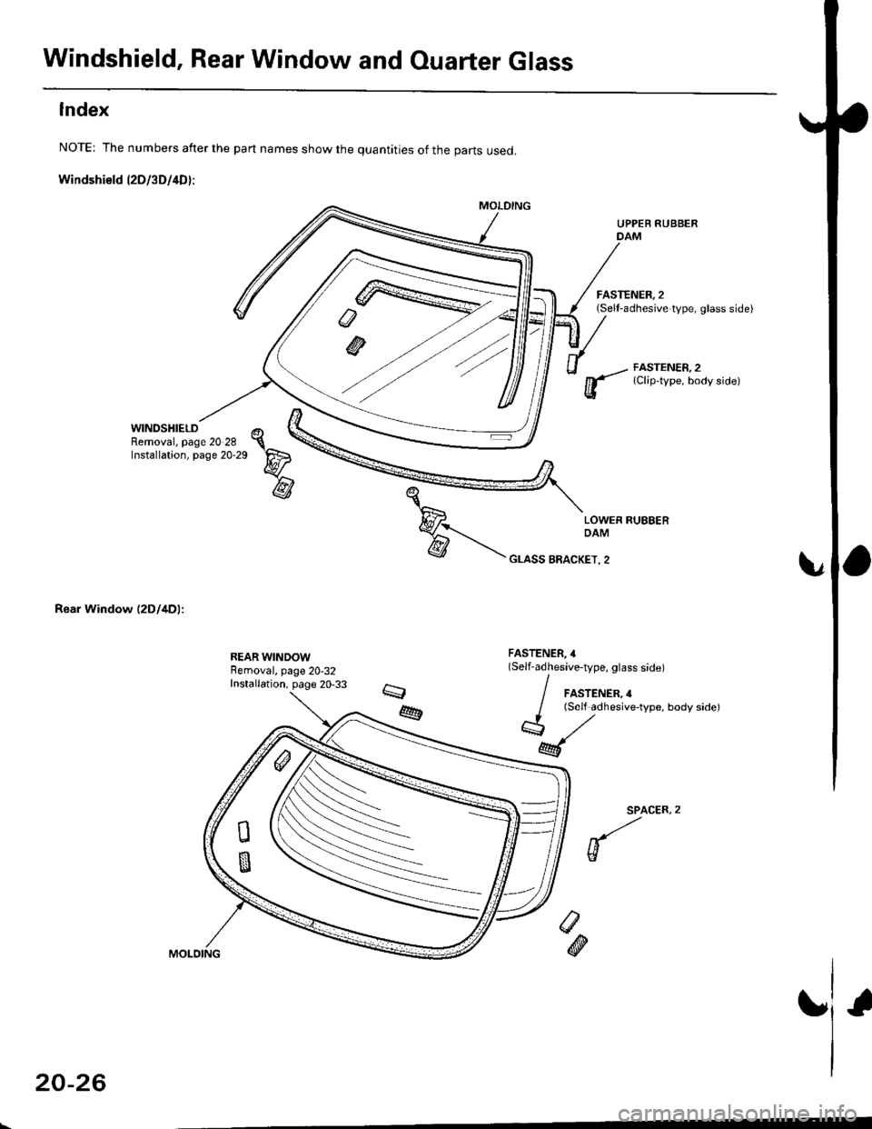
Windshield, Rear Window and Ouarter Glass
Index
NOTE: The numbers after the part names show the quantities of the parts used.
Windshield l2Dl3D/4D):
WINDSHIELDRemoval, page 20 28Installation, page 20-29
Rear Window (2Dl4Dl:
UPPER RUBBERDAM
FASTENER, 2(Sell-adhesive type, glass side)
FASTENER, 2lClip-type, body side)
FASTENER, 4(Self-adhesive-type, glass side)
/ FASTENER,4
/ lSelf adhesive-type, body sidel
*,/
M
SPACER,
w
/>
@
20-26
Page 1257 of 2189
b
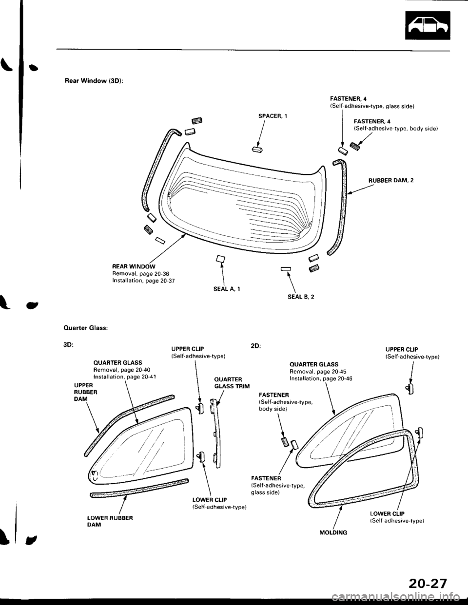
Rear Window l3Dl:
SPACER,
I
| ,o"r.".". o
{ff*'*'YPe
bod'side)
FASTENER,4(Self-adhesive-type, glass side)
RUBBER DAM,2
tIISEAL A, 1
=@
SEAL B, 2
e
Ouarter Glass:
3D:
OUARTER GLASSRemoval, page 20-40Installation, page 20 4lOUARTERGLASS TRIM
LOWER CLIPlSelf adhesive'type)
2D:
FASTENER(Self-adhesive-type,glass side)
FASTENER(Self-adhesave type,body side)
\
\
)f\
n,
$(
\il]
LOWER RUBBERDAM
LOWER CLIP(Self adhesive-type)
J
20-27
Page 1258 of 2189
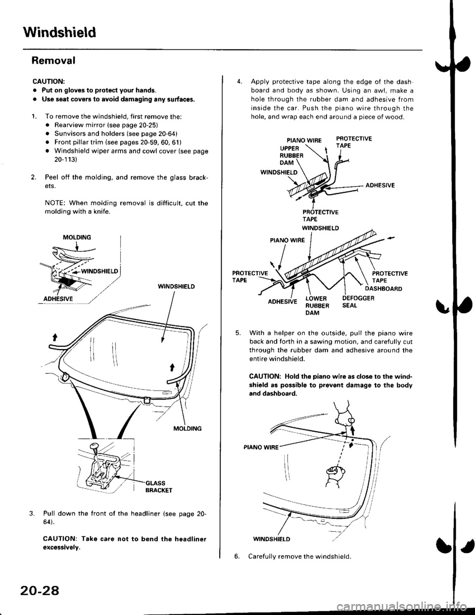
Windshield
Removal
CAUTION:
. Put on gloves to plotest your h8nds.
. Use seat covers to avoid damaging any surfaces.
1. To remove the windshield, first remove the:. Rearview mirror (see page 20-25)
. Sunvisors and holders (see page 20-64)
. Front pillar trim (see pages 20-59, 60, 61)
! Windshield wiper arms and cowl cover (see page
20-1131
Peel off the molding, and remove the glass brack-
ers.
NOTE: When molding removal is difficult, cut the
molding with a knife.
WINDSHIELO
3. Pull down the front of the headliner (see page 20-
64).
CAUTION: Take care not to bend the headlinet
excsssively.
MOLDING
20-24
4. Apply protective tape along the edge of the dash
board and body as shown. Using an awl, make a
hole through the rubber dam and adhesive from
inside the car. Push the piano wire through the
hole, and wrap each end around a piece of wood-
PIANO WIREPROTECTIVE
UPPERRUBBER| '1"
DAM
WINDSHIELO
AOHESIVE
RUBBERDAM
With a helper on the outside, pull the piano wire
back and forth in a sawing motion, and carefully cut
through the rubber dam and adhesive around the
entire windshield.
CAUTION: Hold the piano wile as close to ihe wind-
shield as possible to prevent damage to the body
and dashboard.
WINDSHIELD
6. Carefully remove the windshield.
Page 1259 of 2189
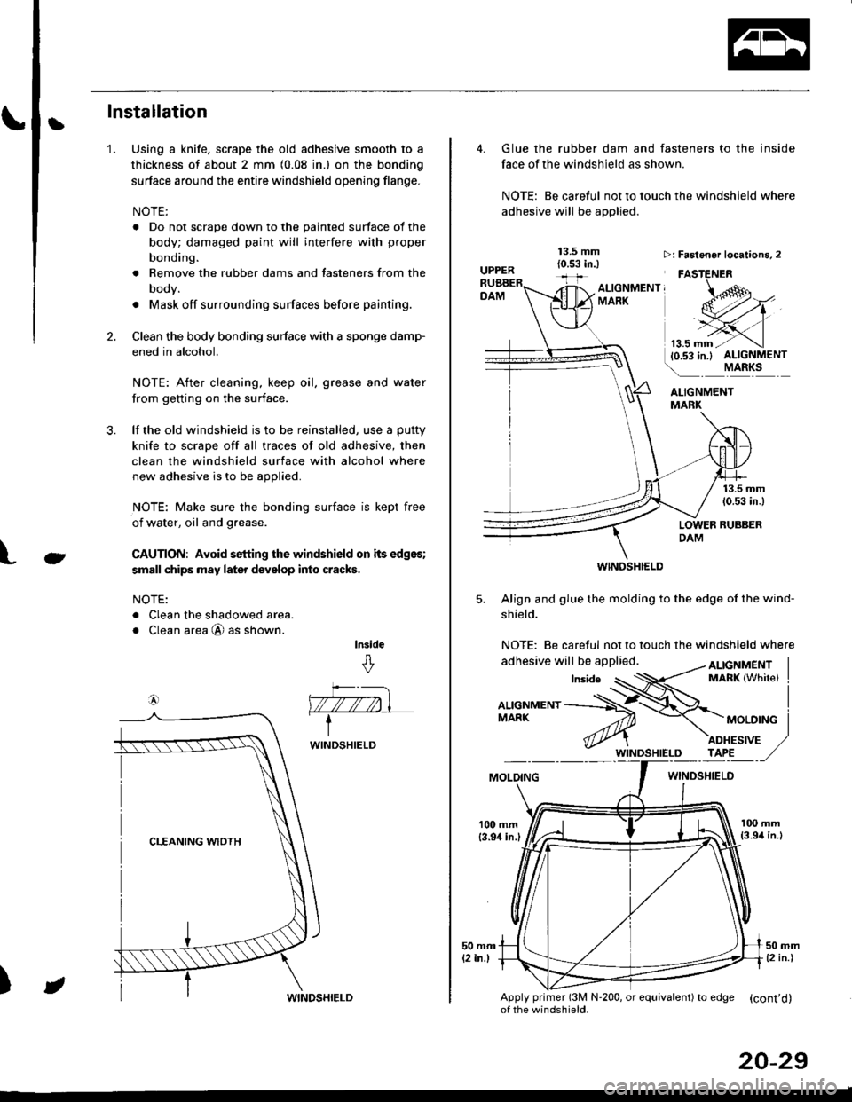
tInstallation
Using a knife, scrape the old adhesive smooth to a
thickness of about 2 mm (0.08 in.) on the bonding
surface around the entire windshield opening flange.
NOTE:
. Do not scrape down to the painted surface of the
body; damaged paint will interfere with proper
bonding.
. Remove the rubber dams and tasteners from the
body.
. Mask off surrounding surfaces before painting.
Clean the body bonding surface with a sponge damp-
ened in alcohol.
NOTE: After cleaning, keep oil, grease and water
from getting on the surface.
lf the old windshield is to be reinstalled, use a putty
knife to scrape off all traces of old adhesive, then
clean the windshield surface with alcohol where
new adhesive is to be applied.
NOTE: Make sure the bonding surface is kept free
of water, oil and grease.
CAUTION: Avoid setting the windshield on its edges;
small chips may later deyelop into cracks.
NOTE:
. Clean the shadowed area.
o Clean area @ as shown.
lnside
&
'1.
2.
3.
Ct
a4)
)
WINDSHIELD
JWINDSHIELD
20-29
Glue the rubber dam and fasteners to the inside
face of the windshield as shown.
NOTE: Be careful not to touch the windshield where
adhesive will be applied.
ALIGNMENTMABK
13.5 mm(0.53 in.)
LOWER RUBBERDAM
WINOSHI€LD
5. Align and glue the molding to the edge of the wind-
shield.
NOTE: Be caretul not to touch the windshield where
>: Faslener localions, 2
FASTENER
ALTGNMENT, -oMARK
MOLOINGWINDSHIELO
100 mm{3.94 in.l
Apply primer (3M N'200, or equivalent) to edSe (cont'd)of the windshield.
Page 1260 of 2189
Windshield
Installation (cont'd)
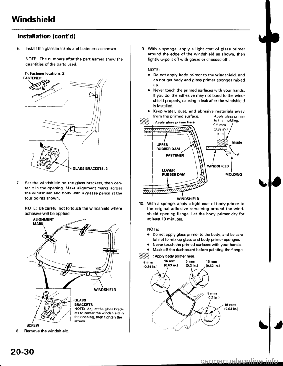
Installthe glass brackets and fasteners as shown.
NOTE: The numbers after the part names show thequantities of the oarts used.
GLASS BRACKETS, 2
Set the windshield on the glass brackets, then cen-
ter it in the opening. Make alignment marks across
the windshield and body with a grease pencil at the
four points shown.
NOTE: Be careful not to touch the windshield where
adhesive will be aDolied.
7.
8. Remove the windshield.
20-30
>: Fastoner locations, 2FASTENER ^ I
I
SCREW
9. With a sponge, apply a light coat of glass primer
around the edge of the windshield as shown. then
lightly wipe it off with gauze or cheesecloth.
NOTE:
. Do not apply body primer to the windshield. and
do not get body and glass primer sponges mixed
up.
. Never touch the primed surfaces with your hands.
lf you do. the adhesive may not bond to the wind-
shield properly, causing a leak after the windshield
is installed.
. Keep water. dust, and abrasrve
from the primed surface.t/////,'/////l I Apply glass p.imer here.
materaals away
Apply glass primerto the molding.
WINDSHIELD
10. With a sponge. apply a light coat of body primer to
the original adhesive remaining around the wind-
shield opening flange. Let the body primer dry for
at least 10 minutes.
NOTE:
. Do not apply glass primer to the body, and be care-
ful not to mix up glass and body primer sponges.
. Never touch the primed surfaces with your hands.
. Mask off the dashboard before painting the flange.7////l/////l I Apply body p mer hcre.
6mm16mm 5mm(0.6:| in.) (0.2 in.l16 mm
{0,63 in.}
/
MOLDING