Power locks HONDA CIVIC 1999 6.G User Guide
[x] Cancel search | Manufacturer: HONDA, Model Year: 1999, Model line: CIVIC, Model: HONDA CIVIC 1999 6.GPages: 2189, PDF Size: 69.39 MB
Page 1728 of 2189
Power Door Locks
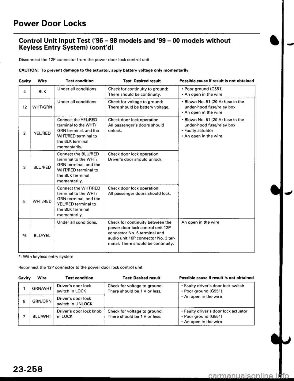
Control Unit lnput Test ('96 - 98 models and'99 - 00 models without
Keyless Entry Systeml (cont'dl
Disconnect the 12P connector from the power door lock control unit.
CAUTION: To prevsnt damage to the actuator, apply battery voltage only momentarily.
Cavity WireTest conditionTest: Desired resultPossible cause if result is nol obtained
*: With keyless entry system
Reconnect the 12P connector to the power door lock control unit.
Cavity WireTest conditionTssl: Desirsd losullPossible cause it resull b not obtained
4BLKUnder all conditionsCheck for continuity to ground:
There should be continuity.
. Poor ground (G55'l ). An open in the wire
WHT/GRN
Under all conditionsCheck for voltage to ground:
There should be battery voltage.
. Blown No. 51 (20 A)fuse in the
under-hood fuse/relay box. An open in the wire
2YEURED
Connect the YEURED
terminal to the WHT/
GRN terminal, and the
WHT/RED terminal to
the BLK terminal
momenraflty.
Check door lock operation:
All passenger's doors should
untocK.
Blown No. 51 {20 A) fuse in the
under-hood fuse/relay box
Faulty actuator
An open in the wire
3BLU/RED
Connect the BLU/RED
terminal to the WHT/
GRN terminal. and the
WHT/RED terminal to
the BLK terminal
momenraflry.
Check door lock operation:
Driver's door should unlock.
5WHT/RED
connect the WHT/RED
terminal to the WHT/
GRN terminal, and the
YEL/RED terminal to
the BLK terminal
momenrafl ty.
Check door lock operation:
All passenger doors should lock.
BLU/YEL
Under all conditions.Check for continuity between the
power door lock control unit l2P
connector No. 6 terminal and
audio unit 16P connector No. 3 ter-
minal: The.e should be continuity.
An open in the wire
GRN,ryVHTDriver's door lock
switch in LOCK
Check for voltage to ground:
There should be 1 V or less.
Faulty driver's door lock switch
Poor ground {G551)
An open in the wire
8GRN/ORNDriver's door lock
switch in UNLOCK
7BLUA/VHT
Driver's door lock knob
in LOCK
Check for voltage to ground:
There should be 1 V or less.
Faulty driver's door lock actuator
Poor ground {G551)
An open in the wire
Page 1730 of 2189
Power Door Locks
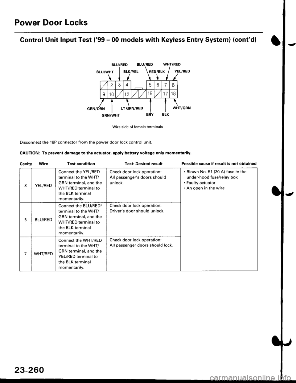
Control Unit Input Test ('99 - 00 models with Keyless Entry System) (cont'd)
BLU/RED WHT/RED
8LU/WHT8LK/YELRED/BLK
2345618
91012/t/t517td
LT GRN,/RED
BLK
Wire side of female terminals
Disconnect the 18P connector from the oower door lock control unit.
CAUTION: To prevent damage to the actuator, apply baftery voltage only momentarily.
Cavity WileTest conditionTest: Desired resultPossible cause if result is not obtained
BLU/RED
YEL/RED
WHT/GRN
GRN/WHT
IYEURED
Connect the YEURED
terminal to the WHT/
GRN terminal, and the
WHT/RED terminal to
the BLK terminal
momenraflty,
Check door lock operation:
All passenger's doors should
untocK.
Blown No. 51 (20 A) fuse in the
under-hood fuse/relay box
Faulty actuator
An open in the wire
5BLU/RED
Connect rhe BLU/RED1
terminal to the WHT/
GRN terminal, and the
WHT/RED terminal to
the BLK terminal
momenlaflry_
Check door lock operation:
Driver's door should unlock.
7WHT/RED
Connect the WHT/RED
terminal to the WHT/
GRN terminal, and the
YEURED terminal to
the BLK terminal
momenlaflry.
Check door lock operation:
All passenger doors should lock.
23-260
Page 1732 of 2189
Power Door Locks
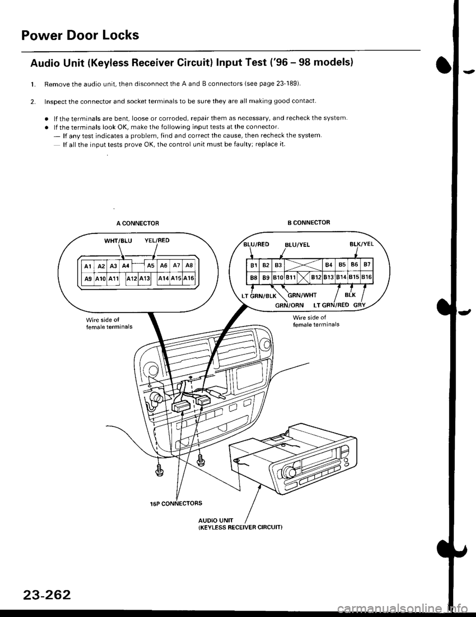
Audio Unit {Keyless Receiver Circuitl Input Test ('96 - 98 models}
Remove the audio unit, then disconnect the A and B connectors (see page 23-189).
Inspect the connector and socket terminals to be sure they are all making good contact
. lf the terminals are bent, loose or corroded, repair them as necessary, and recheck the system
. lf the terminals look OK, make the following input tests at the connector.
- lf anv test indicates a problem, find and correct the cause, then recheck the system
lf all the inout tests prove OK, the control unit must be faulty; replace it.
A CONNECTOBB CONNECTOR
16P CONNECTORS
AUDIO UNIT
L
2.
WHT/BLU YEL/RED
{KEYLESS RECEIVER CIRCUIT}
23-262
Page 1734 of 2189
Power Door Locks
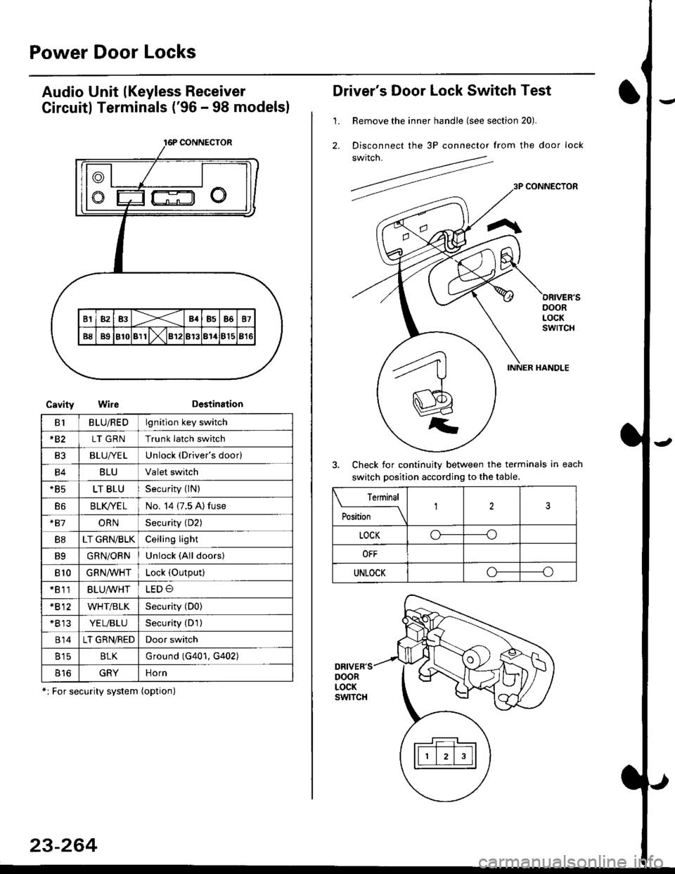
Audio Unit lKeyless Receiver
Circuitl Terminals ('96 - 98 modelsl
CavityWireDestination
16P CONNECTOR
B1BLU/REDlgnition key switch
*82LT GRNTrunk latch switch
Ft2BLU/YELUnlock (Driver's door)
B4BLUValet switch
*85LT BLUSecurity {lN)
B6BLK/YE LNo. 14 (7.5 A) fuse
*81ORNSecurity (D2)
B8LT GRN/BLKCeiling light
B9GRN/ORNUnlock (All doors)
810GRNA/VHTLock (OutPutl
*811BLU/WHTLED O
*812WHT/BLKSecurity (D0)
+B 13YEL/BLUSecurity (D'l )
814LT GRN/REDDoor switch
B15BLKG round (G401, G402)
o toGRYnorn
*: For security system (option)
23-264
Driver's Door Lock Switch Test
1. Remove the inner handle (see section 20).
2. Disconnect the 3P connector from the door lock
switch.
Check for continuity between the terminals in each
switch position according to the table.
DRIVER'SDOORLOCKswtTcH
Terminal
Position123
LOCKo-----o
OFF
UNLOCKo----o
Page 1736 of 2189
Power Door Locks
Transmitter Test
NOTE:
. lf the doors unlock or lock with the transmitter, but
the LED on the transmitter does not come on, the
LED is faulty; replace the transmitter.
. lf any door is open, you cannot lock or unlock the
door with the transmitter.
. lf you unlocked the doors with thetransmitter, but do
not open any of the doors within 30 seconds, the
doors relock automatically.
. The doors do not lock or unlock with the transmitter
if the ignition key is inserted in the ignition switch.
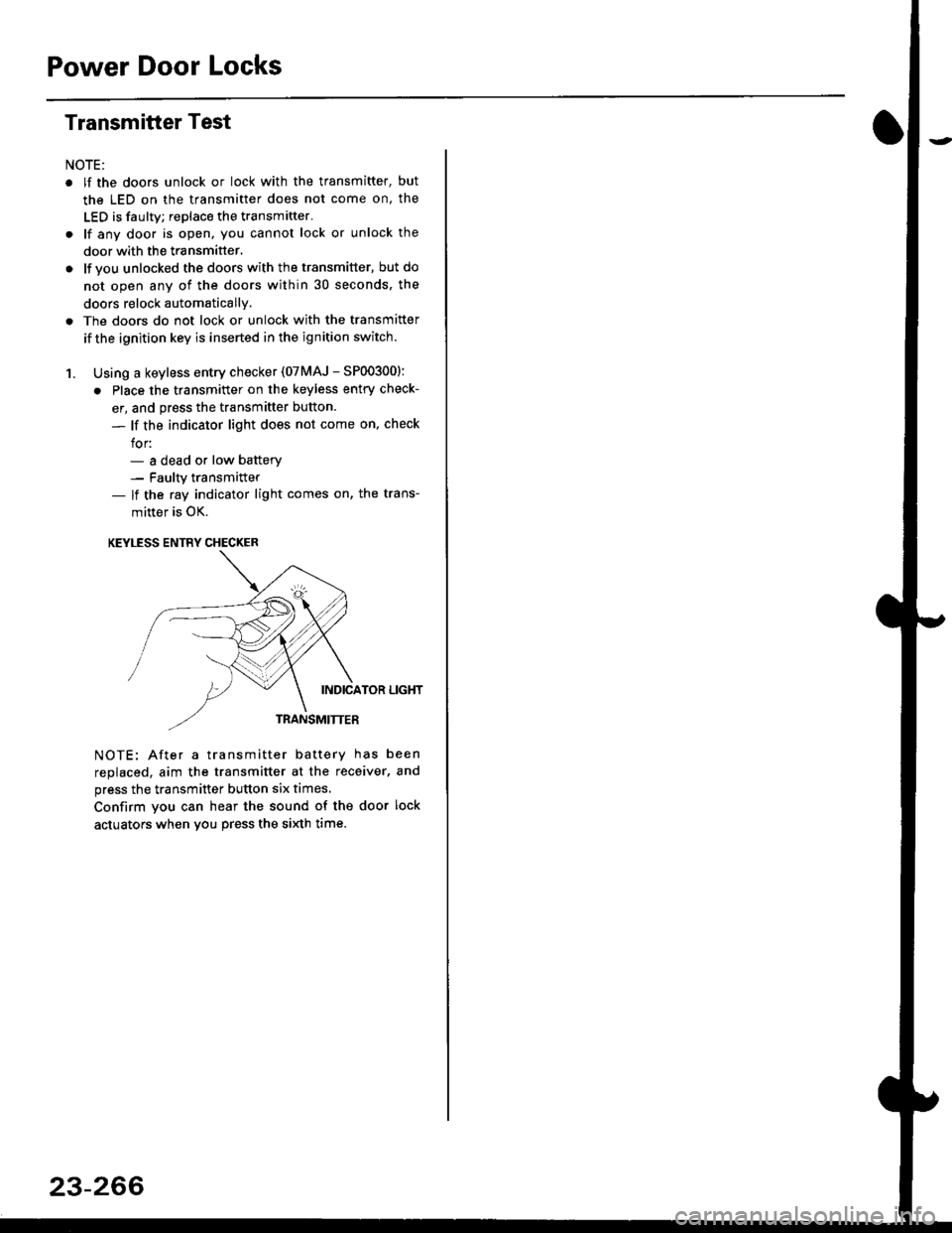
1. Using a keyless entry checker (07MAJ - SP003001:
. Place the transmitter on the keyless entry check-
er, and press the transmitter button.
- lf the indicator light does not come on, check
for:- a dead or low batterv- Faulty transmitter- lf the ray indicator light comes on, the trans-
mitter is OK.
KEYLESS ENTRY CHECKER
INDICATOR LIGHT
TRANSMITTER
NOTE: After a transmitter battery has been
replaced, aim the transmitter at the receiver, and
press the transmitter button six times,
Confirm you can hear the sound of the door lock
actuators when vou press the si)dh time.
23-266
Page 1738 of 2189
Power Door Locks
Transmitter Programming ('99 - 00 modelsl
Storing transmitter codes;
The codes of up to three transmitters can be read into
the keyless receiver unit memory. (lf a fourth code is
stored, the code which was input first will be erased.)
NOTE: lt is important to maintain the time limits
between the steps.
'1. Turn the ignition switch ON (ll).
2. Within 1 to 4 sec., push the transmitter lock or unlock
button with the transmitter aimed at the vehicle.
3. Within I to 4 sec., turn the ignition switch OFF.
4. Within 1 to 4 sec., turn the ignition switch ON 1ll).
5. Within 1 to 4 sec., push the transmitter lock or
unlock button with the transmitter aimed at the
vehicle.
6. Within 1 to 4 sec., turn the ignition switch OFF.
7. Within 4 sec., turn the ignition switch ON (ll).
8. Within 1 to 4 sec., push the transmitter lock or
unlock button with the transmitter aimed at the
vehicle.
9.Within 1 to 4 sec., turn the ignition switch OFF.
Within 4 sec., turn the ignition switch ON (ll).
Within '1 to 4 sec., push the transmitter lock or
unlock button with the transmitter aimed at the
vehicle.
Confirm you can hear the sound of the door lock
acIuarors.
Within 8 sec., aim the transmitters (up to three)
whose codes you want to store at the receiver, and
press the transmitter lock or unlock buttons.
Contirm that you can hear the sound of the door
lock actuators after each transmitter code is stored.
Turn the ignition switch OFF, and pull out the key.
Confirm proper operation with the new code(s).
'10.
11.
12.
14.
23-268
Page 1748 of 2189
Preca utions/Procedures
Spring-loaded Lock Connector
Some SRS system connectors have a spring-loaded lock.
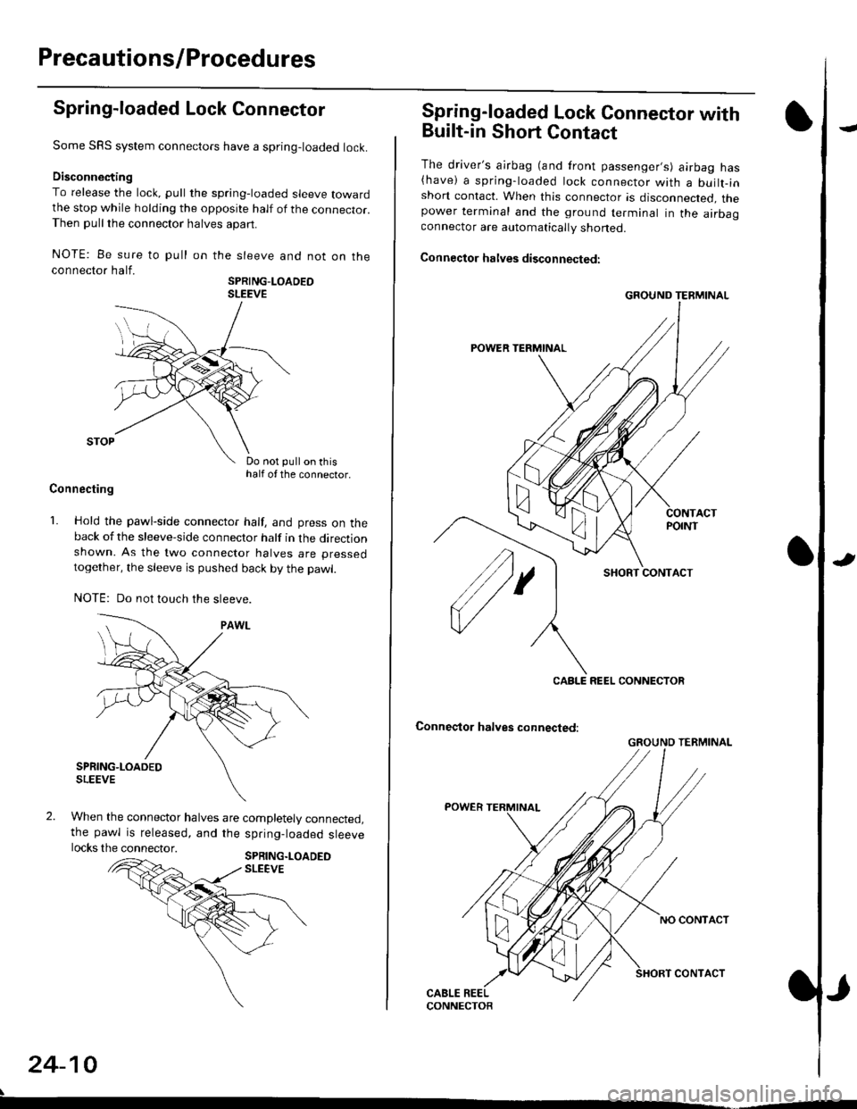
Disconnecting
To release the lock, pull the spring-loaded sleeve towardthe stop while holding the opposite half of the connecror.Then pull the connector halves apart.
NOTE: Be sure to pull
connector half.
on the sleeve and not on the
SPRING-LOADEOSLEEVE
Do not pull on thishalf of the connector.
Connecting
1. Hold the pawl-side connector half, and press on theback of the sleeve-side connector half in the directionshown. As the two connector halves are pressed
together, the sleeve is pushed back by the pawl.
NOTE: Do not touch the sleeve.
When the connector halves are completely connected,the pawl is released, and the spring-loaded sleevelocks the connector.SPRING.LOADEDSLEEVE
24-10
Spring-loaded Lock Connector with
Built-in Short Contact
The driver's ajrbag (and front passenger,s) airbag has(have) a spring-loaded lock connector with a builr-inshort contact. When this connector is disconnected, thepower terminal and the ground terminal in the airbaaconnector are automatically shoned.
Connector halves disconnected:
SHORT CONTACT
Conneqtor halves connected:
GROUND TERMINAL
CABLE REEL CONNECTOR
GROUND TERMINAL
Page 1817 of 2189

Contents
How to Use This Manual ICircuit Schematics (see Circuit Index)Fuse/Relaylnformation 6Ground-to-Componentslndex 6-6ComponentLocationPhotooraohs 201Conriector Views 202
Circuit Index
Accessory power socket 155Air conditionerAir delivery'96198 models 61'99-'00 models 61-2Blower controls'96198 models 60'99100 models 60-1Compressor controls 62Fans 63Anti-lock brake system (ABS) 44A/T gear position indicatorCVT 89All except CVT 89-1Automatic transmission controlsAll '96-'98 models except CVT and GX 39All '99100 models except CVT 39-8All GX models 39-8'96-'�98 CVT 39-4'99100 cw 39-12Back-up lightsCoupe and Sedan 110Hatchback l'10-1Brake lightsAll Coupes and'96-'98 Sedans 110-15'99-'00 Sedans 110-16Hatchback 110-17Brake system indicator light'96198 models 7'1'99100 models 71-1Ceiling light 114-3Charging system 22Condenser fan 63Console lights 114Cruise control 34Dash lights 114Daytime running lights 110- 13Engine coolant temperature gauge 81-1Fog lights 110-10Front parking lights 110-2Fuel gauge 81-1Fuse/relay boxUnder-dash 6Under-hood 6-4Underhood ABS 6-3Gauges 81Ground distribution 14Ground-to-Componentslndex 6-6Hazard warning lightsAll except '99100 Sedans 110-6'99100 Sedans 110-8Headlights 110-12Headlight switch 100Heater - See Air ConditionerHorn'96197 models 40'98 model 40-1'99100 models 40-2lgnition key reminder 73lgnition systemAll '96198 models except Dl685 20All '99100 models except D16Y5 with Mn 2O-2All D1685 engines 20-2'99-'00 D 16Y5 with M/T 20
lndicators 80Integrated control unit 70lnterlock systemAll except'96J98 CVT 138'96198CVT 138-1License plate lightsAll Coupes and '96-'98 Sedans I l0-3'99100 Sedans 1 10-4Hatchback 110-5Low fuel indicator light 74Moonrool'96197 models |22'98-'00 models 122-1Odometer 81Oil pressure indicator light 80-3Power distributionBattery to ignition switch, fuses, and relaysFuses to relays and components 10-2Power door locksAll models without keyless entry 130'96-'98 models with keyless entry 130-2'99100 models with keyless entry 130-12Power mirrorsWithout detogger 141With defogger '141-2
Power windows 120Programmed fuel injection system (PGNr-Fl)All '96-98 models except D1685 23All '99-'00 models except D16Y5with M/T and D1685 24All D1685 engines 25'99100 D16Y5 with M/T 23Radiator fan 63Rear window defogger'96-,98 models 64'99100 models 64-1Seat belt reminder 73Security system'96.'98 USA HX, LX, EX 133'96-'98 Canada EX, Si 133'99TOO USA HX, LX, EX, DX.V Si 133-4'99100 Canada EX, Si 133-4All CX and DX models 133-8Speedometer 81Starting systemA./T (All except Dl685) 21A"/r (D16Bs) 21-1Manualtransmission 21-2Slereo sound system 150Supplemental rastraint system (SRS) 47Tachometer 81TailliqhtsAllboupes and'96-'98 Sedans 110-3'99100 Sedans 1 10-4Hatchback 110-5Trunk light 114-3Turn signal lightsAll except'99100 Sedans 110-6'99-'00 Sedans 1 10-8Vehicle speed sensor (VSS) 33Wiper/washerFront 91Rear 92
10
Page 1827 of 2189
How To Use This Manual
Symbols
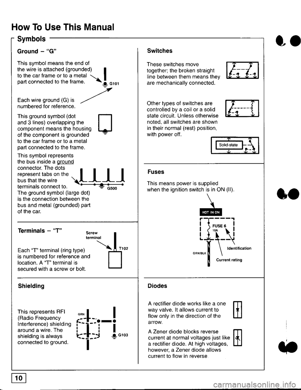
Ground - "G"
This symbol means the end ol
the wire is attached (grounded) Ito the car frame or to a metal I
part connected to the frame. \i oro,|
-t'
Each wire ground (G) it --/
numbered for reference.
oo
Switches
These switches move
together; the broken straight
line between them means the,
are mechanically connected.
Other types of switches are
controlled by a coil or a solid
state circuit. Unless otherwise
noted. all switches are shown
in their normal (rest) position,
with power off.
This ground symbol (dot
and 3 lines) overlapping the
component means the housing
of the component is grounded
to the car frame or to a metal
part connected to the frame.
This symbol represents
the bus inside a ground
connector. The dots I
i:l*,':1,'^:*,:"
;"
r"L I I I
terminals connect to.
The ground symbol (large dot)
is the connection between the
bus and metal (grounded) part
of the car.
Terminals - "T"
ffi
ffi
Solid-state
Fuses
This means power is supplied
when the ignition switch is in ON (ll).
Current rating
Diodes
A rectifier diode works like a one
way valve. lt allows current to
llow only in the direction of the
arrow.
A Zener diode blocks reverse
current at normal voltages just like
a rectifier diode. At high voltages.
however, a Zener diode allows
current to f low in reverse
oo
Each "T" lerminal (ring type)
is numbered for reference and
location. A "T" terminal is
secured with a screw or bolt.
Shielding
This represents RFI
(Radio Frequency
Interference) shielding
around a wire. The
shielding is always
connected to ground.
f--l;j-i",..
I
,,,,
T
Page 1865 of 2189
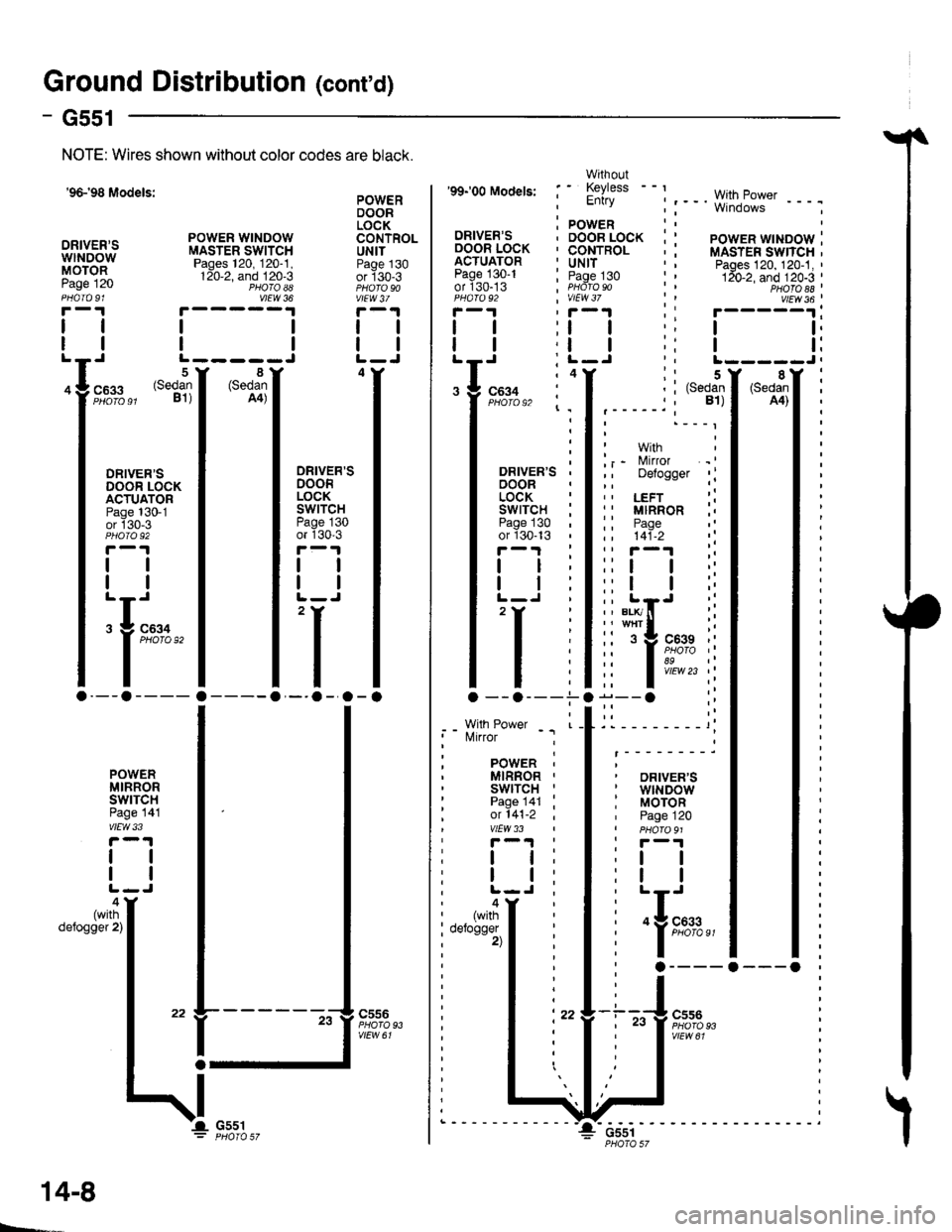
Ground Distribution (cont'd)
1
- G551
Page
I
I
'96-'98 Models:
DRIVER'SwtNDowMOTOR
NOTE: Wires shown without color codes are black.
4
12091
I
I
c633
oRrvER'sDOOR LOCKACTUATORPage 130-1or 130-3
tl
tl
:f ;'*"
.--a ----
sl)
POWER WINDOWMASTER SWITCHPages 120, 120-1,120-2, and 120-3PHO|O AAvlEW 36
tl
tlL-----J
POWERDOORLOCKCONTROLUNITPage 130or 130-3
vlEW3/
tl
tl
4
c556
vtEw 61
8(SedanA4)
DRIVER'SDOORLOCKswrTcHPage 130or 130-3
tl
tl
,I
'-.o -.o -
POWERMIRRORswrTcHPage 141vlEw 33
ll
tl
4(withdefogger 2)
G55t
14-8