ecu connector HONDA CIVIC 1999 6.G User Guide
[x] Cancel search | Manufacturer: HONDA, Model Year: 1999, Model line: CIVIC, Model: HONDA CIVIC 1999 6.GPages: 2189, PDF Size: 69.39 MB
Page 979 of 2189
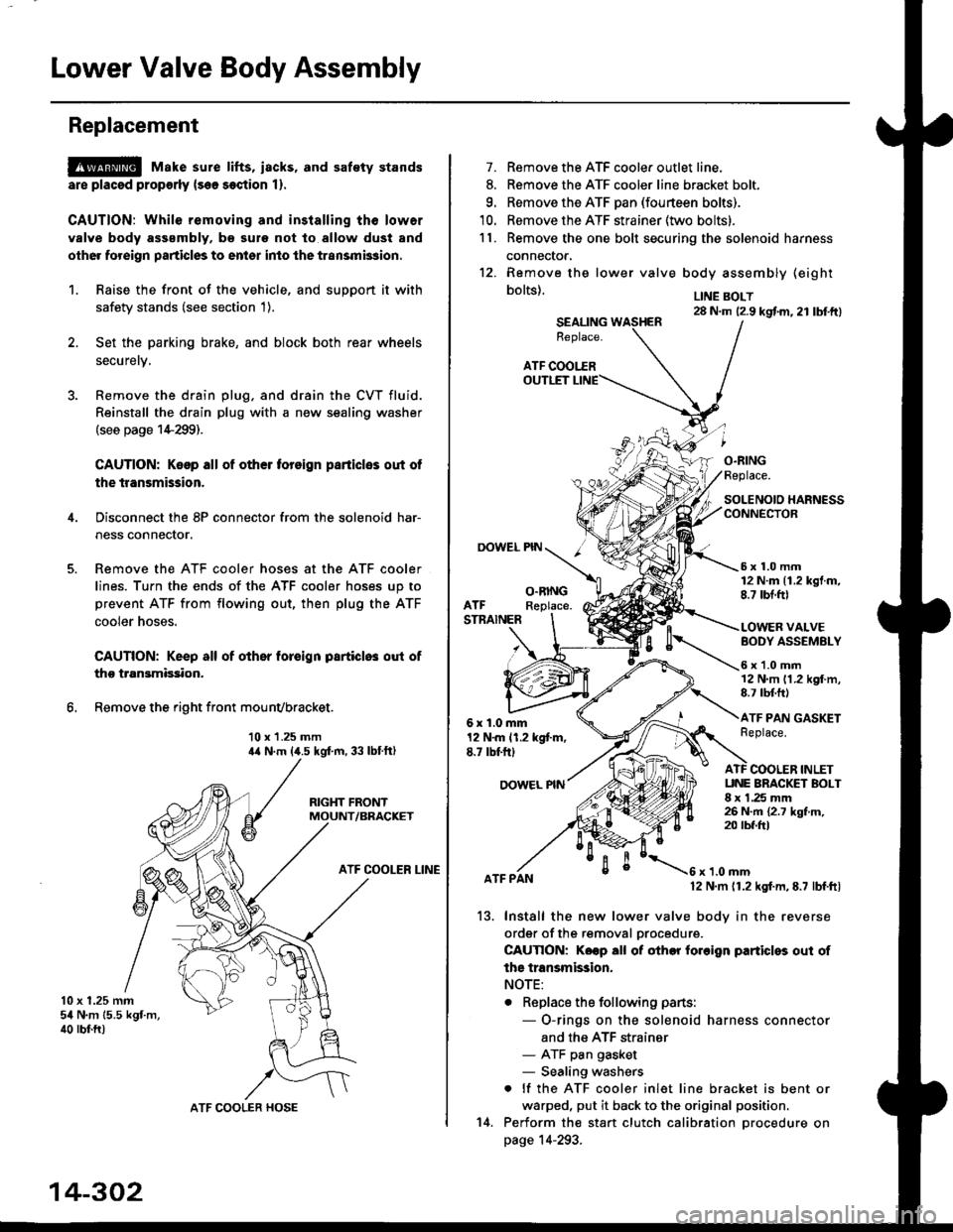
Lower Valve Body Assembly
Replacement
@ Make sure lifts, iacks, and saf€ty stands
are placsd prop€rly {sea section 1).
CAUTION: While removing and installing th6 lower
valve body asssmbly, b€ sule not to allow dust and
other for€ign particles to entsr inio the transmksion.
1. Raise the front of the vehicle, and support it with
safetv stands (see section 1).
2. Set the parking brake, and block both rear wheels
securetv.
4.
6.
Remove the drain plug, and drain the CVT fluid.
Reinstall the drain plug with a new sealing washer(see page 1+299).
CAUTION: Keop all of other toreign parliclos out of
the transmission.
Disconnect the 8P connector from the solenoid har-
ness connector.
Remove the ATF cooler hoses at the ATF cooler
lines. Turn the ends of the ATF cooler hoses up to
prevent ATF from flowing out, then plug the ATF
cooler noses.
CAUTION: Keep all of other foroign particlo3 out of
tho transmission.
Remove the right front mounvbracket.
10 x 1.25 mmila N.m (,1.5 kgf.m, 33 lbtft)
RIGHT FRONTMOUNT/BRACKET
ATF COOLER LINE
10 x 1.25 mmsil N.m 15.5 kgf.m,40 rbr.ft)
ATF COOLER HOSE
14-302
14.
7. Remove the ATF cooler outlet line.
8. Remove the ATF cooler line bracket bolt.
9. Remove the ATF pan (fourteen bolts).
10. Remove the ATF strainer (two bolts).
1 l. Remove the one bolt securing the solenoid harness
connector,
12. Remove the
bolts).
lower valve body assembly (eight
LINE BOLT28 N.m (2.9 kgtm,21 lbtft)SEALINGReplace.
ATF COOI.-EROUTLET
OOWEL PIN
O.RINGFeplace.
SOLENOIO HARNESSCONNECTOR
5x1.0mm12 N.m 11.2 kgt.m,8.7 tbt.ftlO.RINGReplace.ATFSTNAINER
6x1.0mm12 N.m 11.2 kgt m,E.7 tbt'ft)
OOWEL NN
BODY ASSEMBLY
6x1.0mm12 N.m 11.2 kgf.m,8.7 rbf.ft)
ATF PAN GASKETReplace.
VALVE
ATF COOLER INLETUNE BRACKET BOLT8 x 1,25 mm26 N.m {2.7 kgf.m,20 tbf.frl
13.
ATF PANx 1.0 mm12 N.m 11.2 kgf.m, E.7 lbf.ftl
Install the new lower valve bodv in the reverse
ordgr of the removal orocedure.
CAUTION: Koep all ot other fo.oign particles out of
ths transmission.
NOTE:
. Replace the following parts:
- O-rings on the solenoid harness connector
and the ATF strainer- ATF pan gasket- Sealing washers
. lf the ATF cooler inlet line bracket is bent or
warped, put it back to the original position.
Perform the start clutch calibration orocedure on
page 14-293.
Page 992 of 2189
l.
'1.
2.
5.
6.
7.
Remove the ATF cooler inlet iine bracket bolt'
Remove the ATF cooler outlet line
Remove the ATF pan (fourteen bolts).
Remove the ATF strainer {two bolts)
Remove the one bolt securing the solenoid harness
connector, then push the connector.
Remove the lower valve body (eight bolts)
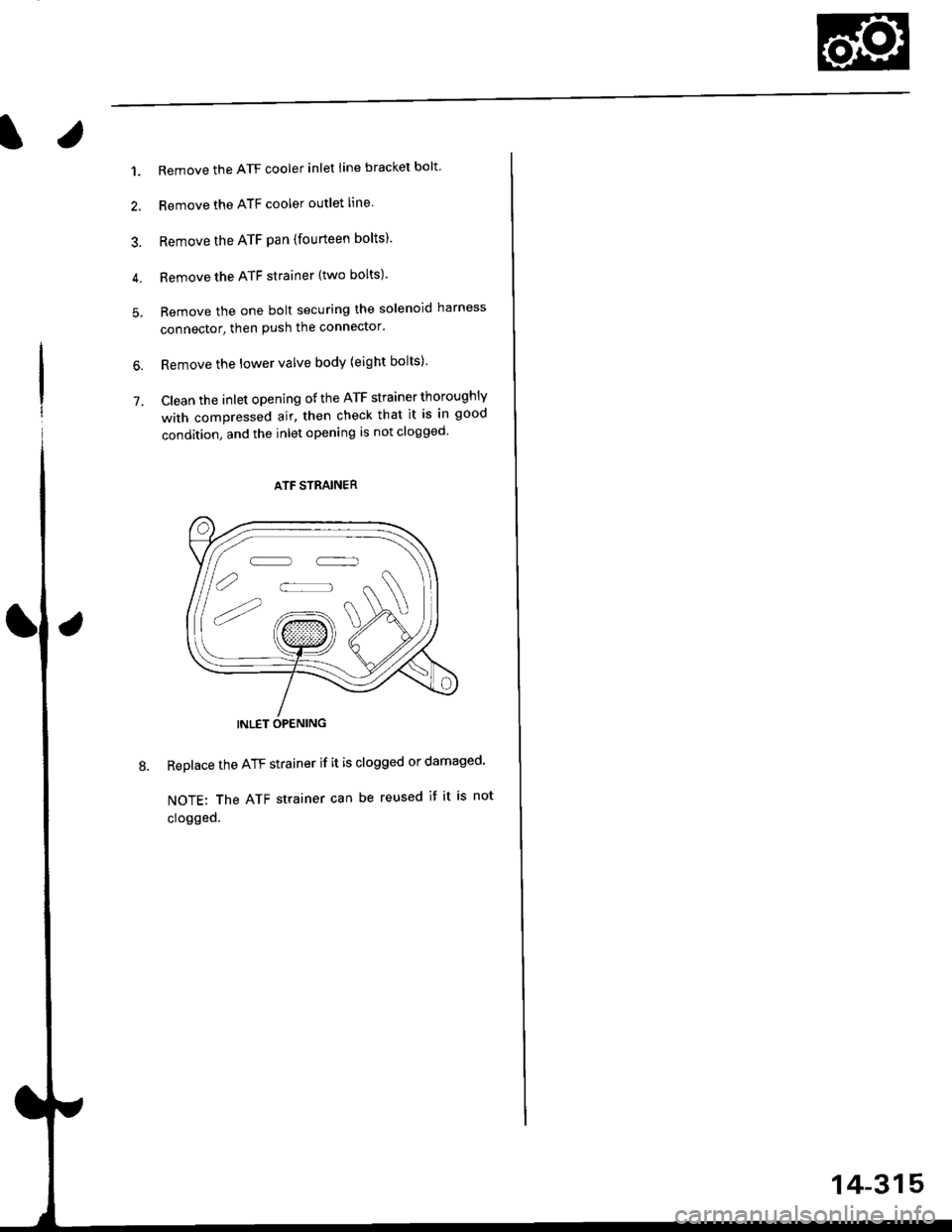
Clean the inlet opening of the ATF strainer thoroughly
with compressed air, then check that it is in good
condition, and the inlet opening is not clogged'
ATF STRAINER
INLET OPENING
Replace the ATF strainer if it is clogged or damaged
NOTE: The ATF strainer can be reused it it is not
clogged.
2c'
c;2 ar\
14-315
Page 1093 of 2189
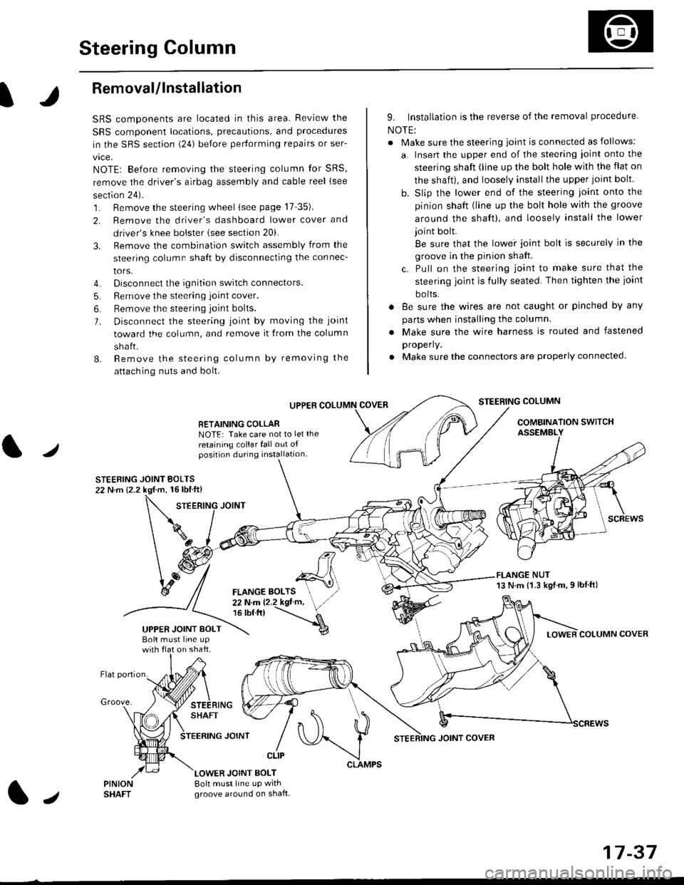
Steering Column
I
Removal/lnstallation
SRS components are located in this area. Review the
SRS component locations, precautions, and proceclures
in the SRS sectron (24) before pertorming repairs or ser-
vice.
NOTE: Before removing the steering column for SRS,
remove the driver's airbag assembly and cable reel lsee
section 24).
1. Remove the steering wheel (see page 17 35).
2. Remove the driver's dashboard lower cover and
driver's knee bolster (see section 20).
3. Remove the combination switch assembly from the
steering column sha{t by disconnecting the connec-
tors.
4. Disconnect the ignition switch connectors.
5. Remove the steering joint cover.
6. Bemove the steering joint bolls.
7. Disconnect the steering ioint by moving the joint
toward the column, and remove it from the column
shaft.
8. Remove the steering column by removing the
attaching nuts and bolt.
UPPER
RETAINING COLLABNOTE: Take care not to let the
retaining collar fall out ofposition during installation.
STEERING JOINT BOLTS22 N.m {2.2 kgf.m, 16lbtft}
9. Installation is the reverse of the removal procedure
NOTE:
. Make sure the steering joint is connected as follows:
a. Insert the upper end of the steering ioint onto the
steering shaft (line up the bolt hole with the flat on
the shait), and loosely install the upper joint bolt.
b. Slip the lower end of the steering joint onto the
pinion shaft (line up the bolt hole with the groove
around the shaft), and loosely install the lower
joint bolt.
Be sure that the lowei joint bolt is securely in the
groove in the pinion shaft.
c. Pull on the steering joint to make sure that the
steering joint js fully seated. Then tighten the ioint
bolts.
. 8e sure the wires are not caught or pinched by any
parts when installing the column
. Make sure the wire harness is routed and fastened
properly.
. Make sure the connectors are properly connected.
STEERING COLUMN
COMBINATION SWITCHASSEMBLY
FLANGE NUT13 N.m {1.3 kgl.m.9 lbf ft)
COLUMN COVER
FLANGE BOLTS22Nm12.2kgl'm,16 tbt.tr)
UPPER JOINT BOLTBolt musl line upon shaft.
Groove.
LOWER JOINT BOLT8oh must line up wrthgroove around on shaft.
CLIP
J
JOINT COVER
17-37
Page 1209 of 2189
Diagnostic Trouble Code (DTCI
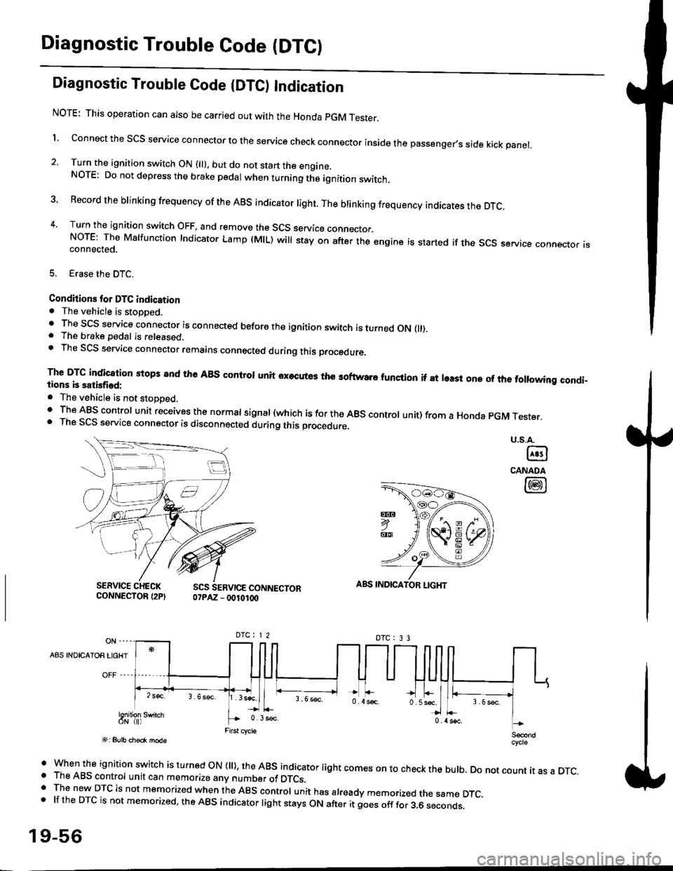
Diagnostic Trouble Code {DTC) Indication
NOTE: This operation can also be carried out with the Honda pGM Tesrer.
l connect the scs service connector to the service check connector inside the passenger,s side kick panel.
2. Turn the ignition switch ON (||). but do not start the engine.NOTE: Do not depress the brake pedal when turning the ignition switch.
3 Record the brinking frequency of the ABS indicator right. The brinking frequency indicates the DTc.
4, Turn the ignition switch OFF, and remove the SCS service connector.NorE: The Mslfunction Indicator Lamp (MlL) will stay on after the engine is started if the scs service connector isconnected.
5. Erase the DTC.
Condhions for DTC indication. The vehicle is stoDDed.. The SCS service connector is connected before the ignition switch is turned ON fll).. The brake pedal is released.. Th€ SCS service connector remains connected during this procedure
The DTG indication stops 8nd the ABs conltol unit executes the softwaro tunqtion if at least one of the following condi-tions b satisfied:
o The vehicle is not stoDoed.' The ABS control unit receives the normat signal (which is for the ABS controt unit) from a Honda pGM Tester.. The SCS service connector is disconnected during this procedu.e,
u.s.A.
@
CANADA
@
SERVICE CHECKCONNECTOR {2PISCS SERVICE CONNECTOR07PAZ - 0010100
ABS INDICATOR LIGHT
DTC : 3 3
A8S INDICAIOR LIGHT
Snilion swirch
' when the ignition switch is turned oN (ll), the ABs indicator light comes on to check the bulb. Do not count it as a DTc.o The ABS control unit can memorize any number of DTCs.. The new DTC is not memorized when the ABS control unit has already memorized the same DTC,.lftheDTCisnotmemorized,theABSindicatorlightstaysONafteritgoesofffor3.6seconds.
19-56
Page 1210 of 2189
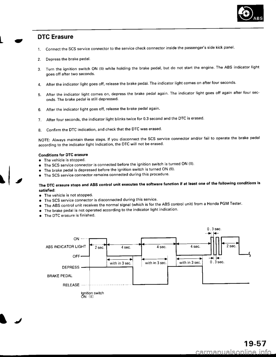
LJDTG Erasure
1.
2.
Connect the SCS service connector to the service check connector inside the passenger's side kick panel.
Depress the brake pedal.
Turn the ignition switch oN (ll) while holding the brake pedal, but do not start the engine. The ABS indicator light
goes off after two seconds.
After the indicator light goes off, release the brake pedal The indicator lightcomeson after four seconds
After the indicator light comes on, depress the brake pedal again. The indicator light goes off again after four sec-
onds. The brake pedal is still depressed.
4.
5.
\t
6. After the jndicator light goes off, release the brake pedal again'
7. After four seconds, the indicator light blinks twice for 0 3 second and the DTC is erased
8. Confirm the DTC indication, and check that the DTC was erased
NOTE: Always maintain these steps. lf you disconnect the scs service connector and/or fail to operate the brake pedal
according to the indicator light indication, the DTC will not be erased
Conditions for DTC erasure
o The vehicle is stopped.
. The SCS service connector is connected before the ignition switch is turned ON {ll)
. The brake pedal is depressed before the ignition switch is turned ON (ll)'
. The SCS service connector remains connected during this procedure
The DTC erasure stops and ABS control unit executes the software lunction it at least one ot the following conditions is
satisfied:
o The vehicle is not stopped.
. The SCS service connector is disconnected during this servace'
.TheABscontro|unitreceivesthenormaIsigna|(whichisfortheAEscontro|unit)fromaHondaPGMTester'
. The brake pedal is not operated according to the indicator light indication
. The DTC erasure is finished
ABS INDICATOR LIGHT
OFF
DEPRESS
BRAKE PEDAL
RELEASE
0.3sec
lqnition switchoN (I)
J
19-57
Page 1307 of 2189
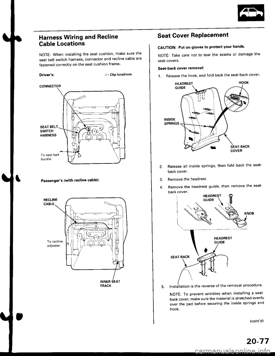
Harness Wiring and Recline
Cable Locations
NOTE: When installing the seat cushion, make sure the
seat belt switch harness, connector and recline cable are
fastened correctly on the seat cushion frame'
Driver's:>: Clip locations
Passenger's (with lecline cablel:
TRACK
Seat Cover RePlacement
CAUTION: Put on gloves to protest yout hands'
NOTE: Take care not to tear the seams or damage the
seat covers.
Seat-back cover removal:
1. Release the hook, and fold back the seat-back cover'
Release all inside springs, then fold back the seat-
back cover.
Remove the headrest.
Remove the headrest guide, then remove the seat-
back cover.
lnst;llation is the reverse of the removal procedure'
NOTE: To prevent wrinkles when installing a seat-
back cover, make sure the material is stretched evenly
over the pad before securing the inside springs and
hook.
3.
(cont'd)
20-77
HEADREST
Page 1342 of 2189
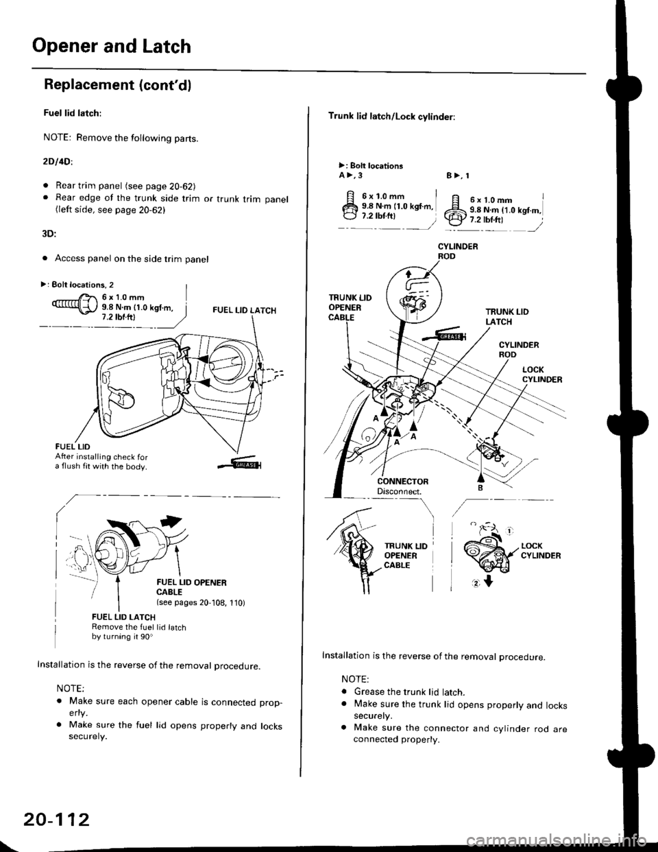
Opener and Latch
Replacement (cont'd)
Fuel lid latch:
NOTE: Remove the following pa(s.
2D l4Dl
. Rear trim panel (see page 20-62J. Rear edge of the trunk side trim or trunk trim panel(left side, see page 20-62)
3D:
. Access panel on the side trim panel
FUEL I-IO LATCH
II
FUEL LID OPENERCABLE(see pages 20,108, 1'10)
FUEL LID LATCHRemove the fuel lid latchby turning it 90o
Installation is the reverse of the removal procedure.
NOTE;
o Make sure each opener cable is connectedelty
. Make sure the fuel lid opens properly andsecurely.
prop-
locks
>: Eolt locations, 2 |r'- 6x10mm9.8 N.m (1.0 kgf.m, I
FUEL LIDAfter installing check fora flush fit with the body.
\
20-112
Trunk lid latch/Lock cylinder:
>: Bolt locationsA >,3
6x1.omm i9.8 N.m (1.0 kgf.m,
:::^ _=)
TRUNK LIDOPENER
CONNECTORDisconnect.-\
TRUNK LIDOPENERCABLE
8>, 1
ff e rt.omm IZS 9.8 N.ln (1.0 kgt m,.ty 7.2-tbr.ftt ,/
CYLINOER
TRUNK LIDLATCH
CYLINDERROD
Installation is the reverse of the removal procedure.
NOTE:
. Grease the trunk lid latch.. Make sure the trunk lid opens properly and lockssecurely.
a Make sure the connector and cylinder rod areconnected property.
Page 1343 of 2189
Windshield Wiper Arms
and Linkage
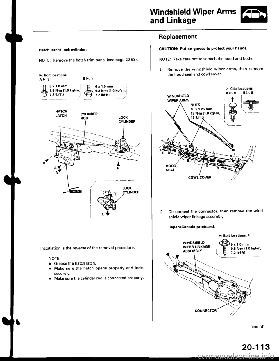
Hatch latch/Lock cylinder:
NOTE: Remove the hatch trim panel (see page 20-63).
>: Bolt locationsA>,3
6x1.0mm I9.8 N.m i1.0 ksf m,l
1.2lbl.trl /
B>, 1
E6'cr
CYLINDER
6;:il;l,lr'.",
.r\
LOCK- r€ cYLTNDERL^ ! ./
rAs<.L ,/
\faa"El
rl
lnstallation is the reverse of the removal procedure.
NOTE:
. Grease the hatch latch.
. Make sure the hatch opens properly and locks
securely.
. Make sure the cylinder rod is connected properly.
Replacement
CAUTION: Pul on gloves to protect your hands
NOTE: Take care not to scratch the hood and body.
1. Remove the windshield wiper arms, then remove
the hood seal and cowl cover.
>: Clip locationsA>,9 B>,9WINOSHIELDWIPER ABMS
\j:_
Hw
u
cowl covER
Disconnect the connector, then
shield wiper linkage assemblY.
Japan/Canada-produced:
remove the wind-
10 x 1.25 mm18 N.m ll.8 kgf m,
(cont'd)
20-113
Page 1363 of 2189
Opener and Latch
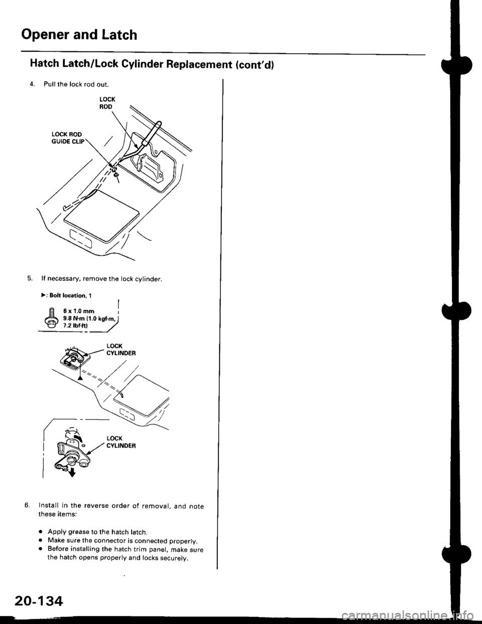
Hatch Latch/Lock Cylinder Replacement (cont'd)
4. Pullthe lock rod out.
lf necessary, remove the lock cylinder.
>: Bolt locelion. 1
6xr.omm I9.8 N.m (1.0 kq .m, I9.8 N.m (1.0 kq .m, I,:!!_J
6. Install in the reverse order of removal, and note
these atems:
. Apply grease to the hatch latch.. Make sure the connector is connected properly.. Before installing the hatch trim panel, make surethe hatch opens properly and locks securely.
ry*)*,,
\""<,/
.z ,/\
20-134
Page 1414 of 2189
Heater Unit
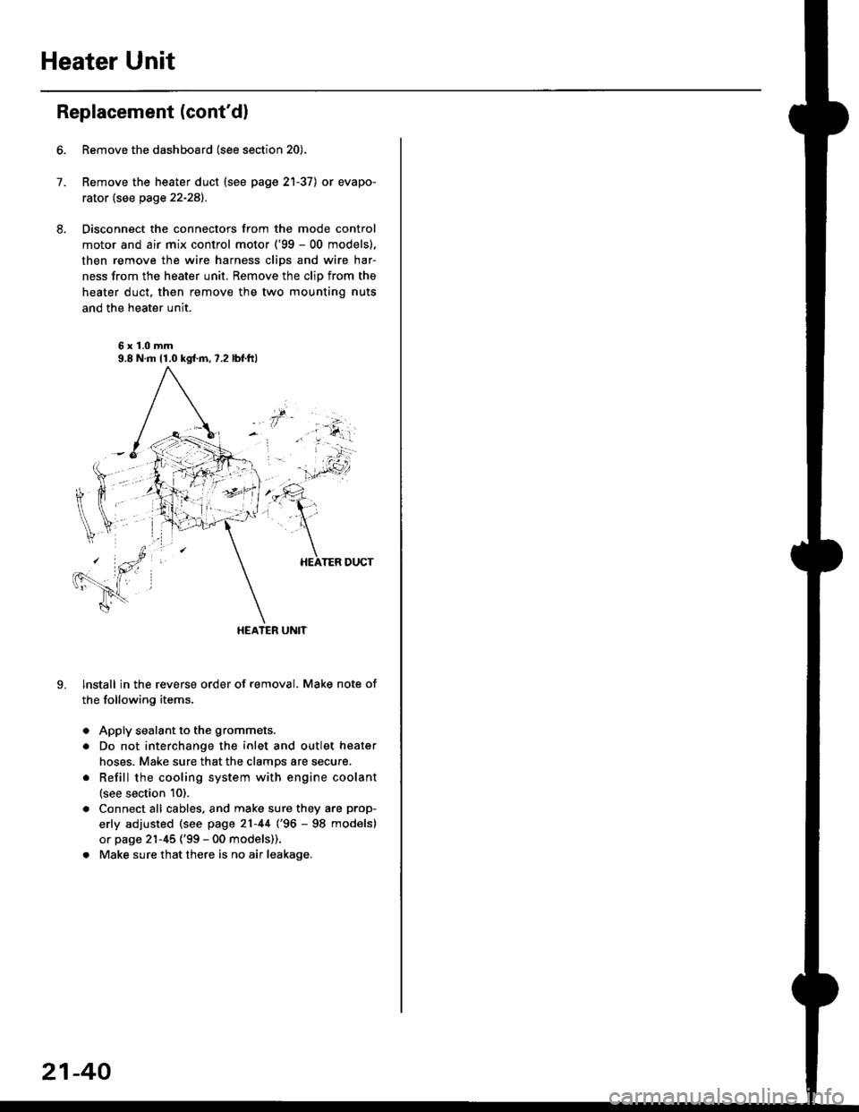
Replacement (cont'dl
6.
7.
8.
9.
Remove the dashboard (see section 20).
Remove the heater duct (see page 21-37) or evapo-
rator (see page 22-28).
Disconnect the connectors from the mode control
motor and air mix control motor ('99 - 00 models),
then remove the wire harness clips and wire har-
ness from the heater unit. Remove the clip from the
heater duct, then remove the two mounting nuts
and the heater unit.
6x1.0mm9.8 N.m 11.0 kgl.m,7.2 lbf.ftl
HEATER UNIT
lnstall in the reverse order of removal. Make note of
the following items.
Apply sealant to the grommets.
Do not interchange the inlet and outlet heater
hoses. Make sure that the clamps are secure.
Refill the cooling system with engine coolant
(see section 10).
Connect all cables, and make sure they are prop-
erly adjusted (see page 21-44 (96 - 98 models)
or page 21-45 ('99 - 00 models)).
Make sure that there is no air leakage.
21-40