link HONDA CIVIC 1999 6.G User Guide
[x] Cancel search | Manufacturer: HONDA, Model Year: 1999, Model line: CIVIC, Model: HONDA CIVIC 1999 6.GPages: 2189, PDF Size: 69.39 MB
Page 435 of 2189
PGM-FI System
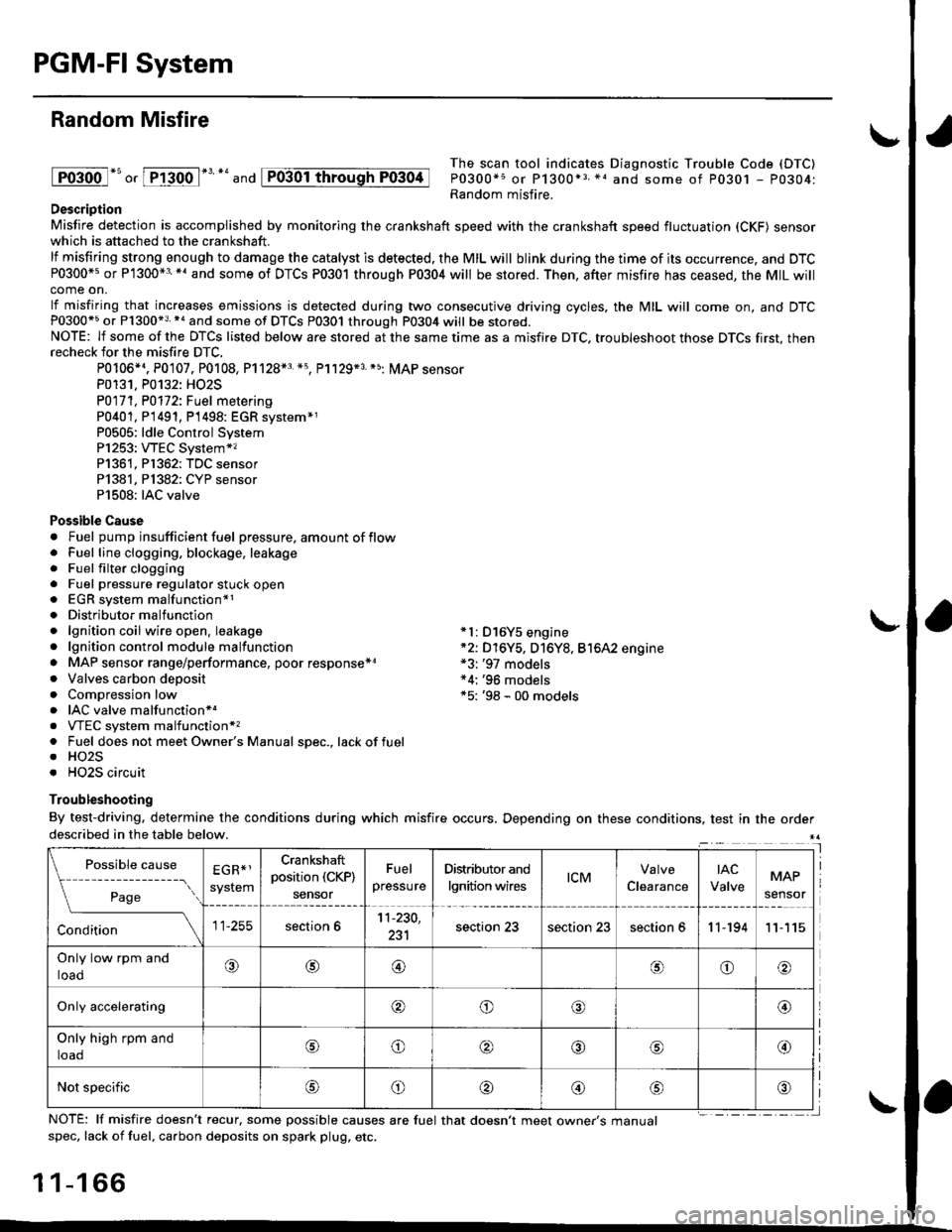
Random Misfire
lFoioo l*u o, [FTioo l*' *' and
The scan tool indicates Diagnostic Trouble Code (DTC)
P0300*5 or P1300*3 *1 and some of P0301 - P0304:Random misfire.Description
Misfire detection is accomplished by monitoring the crankshaft speed with the crankshaft speed fluctuation (CKF) sensorwhich is attached to the crankshaft.
lf misfiring strong enough to damage the catalyst is detected. the MIL will blink during the time of its occurrence, and DTCP0300*5 or P1300*3'*' and some of DTCs P0301 through P0304 will be stored. Then, after misfire has ceased, the MIL willcome on.
lf misfiring that increases emissions is detected during two consecutive driving cycles, the MIL will come on, and DTCP0300*5 or P1300*3 *a and some of DTCS P0301 through P0304 will be stored.NOTE: lf some of the DTCS listed below are stored at the same time as a misfire DTC. troubleshoot those DTCS first, thenrecheck for the misfire DTC.
P0106*4. P0107. P0108, P1128*3 *5, Pl129*3 *5; MAP sensorP0131. P0132: HO2S
P0171, P0112i Fuel metering
P0401, P 1491, P1498: EGR svstem*1P0505: ldle Control SystemP1253: VTEC System*,P1361, P1362: TDC sensorP1381, Pl382: CYP sensorP1508: IAC valve
Possible Cause. Fuel pump insufficient fuel pressure, amount of flow. Fuel line clogging, blockage, leakage. Fuel filter clogging. Fuel pressure regulator stuck open. EGR system malfunction*1. Distributormalfunction. lgnition coil wire open. leakage *l: D16Y5 engine. lgnition control module malfunction *2: D16Y5, D16Y8, Bt6A2 engine. MAP sensor range/performance, poor response*r *3: '97 models. Valves carbon deposit *4;'96 models. Compression low *5: '98 - 00 models. IAC valve malfunctionr.. VTEC system malfunction*,. Fuel does not meet Owner's Manual spec., lackoffuel. HO2S. HO2S circuit
Troubleshooting
By test-driving, determine the conditions during which misfire occurs, Depending on these conditions, test in the orderdescribed in the table below.
Possible
- --^ ---
rage
causeEGR*1
system
Crankshaft
position (CKP)
sensor
Fuel
pressure
Distributor and
lgnition wirestcMClearance
tAc
ValveMAP
sensor
section 611-230,
231section 23section 23section 611-19411
Only low rpm and
loado@@oo
Only accelerating@o@@
Only high rpm and
toaooo@
Not specificoo@
NOTE: lf misfire doesn't recur, some possible causes are fuel that doesn't meet owne/s manualspec, lack of fuel, carbon deposits on spark plug, etc.
1 1-1 66
I
P0304
Page 436 of 2189
I
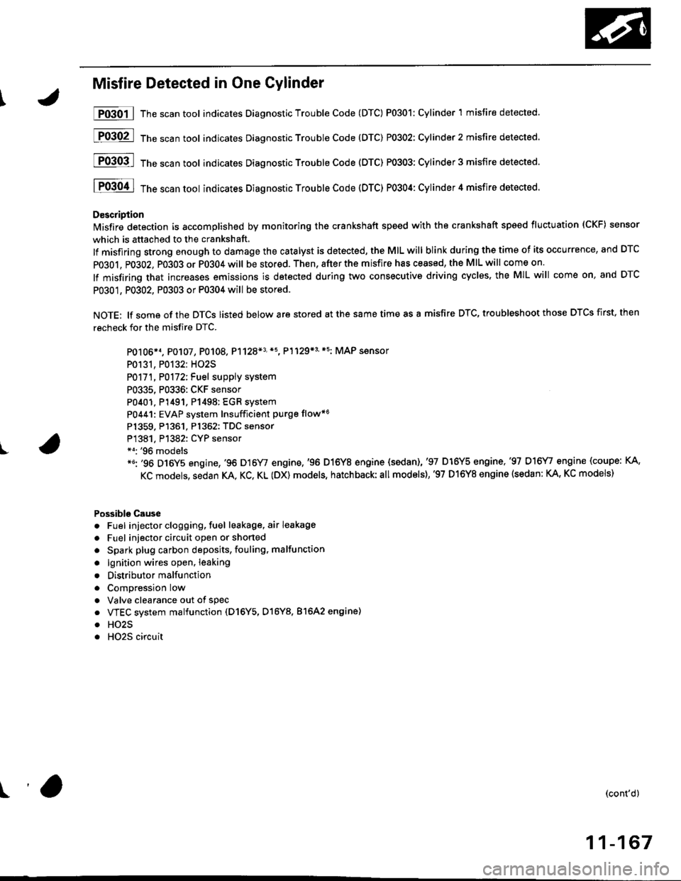
Misfire Detected in One Cylinder
P0301 | The scan tool indicates Diagnostic Trouble Code (DTC) P0301: Cylinder 1 misfire detected.
[F03O2l 16"""untool indicates Diagnostic Trouble code (DTc) P0302: Cylinder2 misfire detected.
[FO3Ofl 16" ".un toot indicates Diagnostic Troubte Code (DTC) P0303; Cylinder 3 misfire detected.
I P0304 I ths..rr tool indicates Diagnostic Trouble Code (DTC) PO3O4: Cylinder 4 misfire detected.
D€scription
lMisfire detection is accomplished by monitoring the crankshaft speed with the crankshaft speed fluctuation (CKF) sensor
which is attached to the crankshaft,
lf misfiring strong enough to damage the catalyst is detected, the MIL will blink during the time of its occurrence, and DTC
PO3O1, P0302, PO3O3 or P0304 will be stored. Then, after the misfire has ceased, the MIL will come on.
lf misfiring that increases emissions is detected during two consecutive driving cyclss, the MIL will come on, and DTC
P0301, P0302, P0303 or P0304 will be stored.
NOTE: lf some of the DTCS listed below are stored at the same time as a misfire DTC, troubleshoot those DTCS first, then
recheck for the misfire DTC.
PO106*1, P0107, P0108. P1128*3'*5, P1129*3'*5: MAP sensor
P0131, P0132: HO2S
P0171, P0172iFuel suppiy system
P0335, P0336: CKF sensor
P0401. P1491, P1498: EGR system
P0441: EVAP system Insufficient purge flow*6
Pl359. P1361. Pl362: TDC sensor
P1381. Pl382: CYP sensor*o: '96 models*6: '96 D16Y5 engine,'96 D16Y/ engine,'96 D16Y8 engine {sedan),'97 D16Y5 engine,'97 D16\4, engine (coupe: KA,
KC models, sedan KA. KC, KL (DX) models, hatchback:all models),'97 D16Y8 engine (sedan: KA, KC models)
Possible Cause
. Fuel injector clogging, fuel leakage, air leakage
. Fuel injector circuit open or shorted
. Spark plug carbon deposits, fouling, malfunction
. lgnition wires open. leaking
. Distributor malfunction
. ComDression low
. Valve clearance out of spec
. VTEC system malfunction (D16Y5, D16Y8. 81642 engine)
. HO2S
. HO2S circuit
(cont'd)
11-167
r'a
Page 513 of 2189
lntake Air System
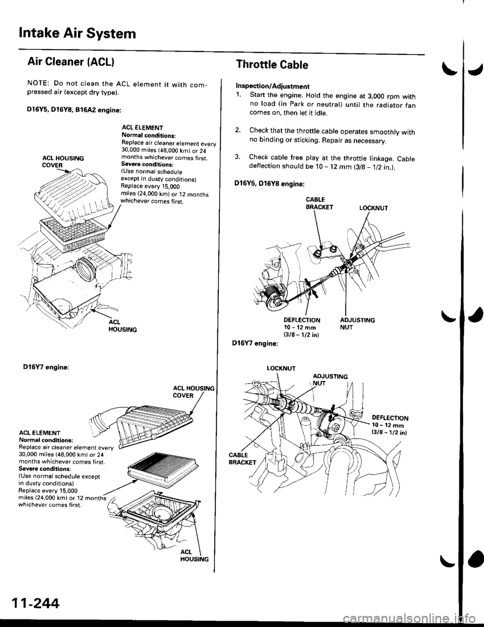
Air Cleaner (ACLI
NOTE: Do not clean the ACL element it with com-pressed air {except dry type).
D16Y5, D16Y8, 816A2 engine:
ACL ELEMENTNormal conditions:Replace air cleaner element every30,000 miles (48,000 km) or 24months whichever comes first.S€voae conditions:(Use normal scheduleexcept in dusty conditions)Replace every 15,OOOmiles (24,000 km)or 12 monthswhichever comes first.
D16Y7 engine:
ACL ELEMENTNormal conditions:Replace air cleaner element every30,000 miles (48,000 km) or 24months whichever comes first,Seve.s conditions:(Use normal schedule exceptin dusty conditions)Replace every l5,000
whichever comes first.
11-244
Throttle Cable
Inspection/Adiustment
1. Start the engine. Hold the engine at 3,000 rpm withno load (in Park or neutral) until the radiator fancomes on, then let it idle.
2. Check that the throftle cable operates smoothly withno binding or sticking. Repair as necessary.
3. Check cable free play at the throttle linkage. Cabledeflection shoutd be 10- l2 mm (3/B - 112 in.l.
D16Y5, D16Y8 engine:
CABLEBRACKETLOCKNUT
DEFLECTION10-12mm
BIA- 112 inl
D16Y7 engine:
LOCKNUT
DEFLECTION10- 12 mml3lA - lninl
Page 514 of 2189
\J
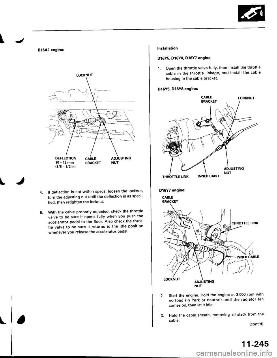
816A2 engine:
DEFLECTION10-12mmBla- 112inl
CABLE ADJUSTINGBRACKET NUT
t
lf deflection is not within specs' loosen the locknut'
turn the adjusting nut untilthe deflection is as speci-
fied, then retighten the locknut.
With the cable properly adiusted, check the thronle
valve to be sure it opens fully when you push the
accelerator pedal to the floor. Also check the throt-
tle valve to be sure it returns to the idle position
whenever you release the accelerator pedal'
LOCKNUT
lnstallation
Dl6Y5, Dr6Y8, D16Y, €ngine:
1. Open the throttle valve fully, then install the throttle
cable in the throttle linkage, and install the cable
housing in the cable bracket.
D16Y5, D16Y8 engins:
LOCKNUT
Start the engine. Hold the engine at 3,000 rpm with
no load (in Park or neutral) until the radiator fan
comes on, then let it idle.
Hold the cable sheath. removing all slack from the
caDle (cont'dl
11-245
Page 515 of 2189
Intake Air System
Throttle Cable (cont'dl
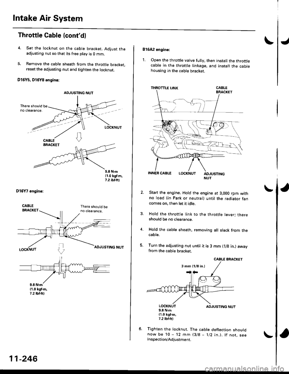
4. Set the locknut on the cable bracket. Adjust theadjusting nut so that its free play is O mm.
5. Bemove the cable sheath from the throttle bracket,reset the adjusting nut and tighten the locknut.
O16Y5, D16Y8 engino:
ADJUSTING NUT
9.8 N.m{1.0 kgl.m,1.2 tbt.ttl
DtGYT 6ngine:
11-246
816A2 engine:
1. Open the throttle valve fully, then install the throttlecable in the throttle linkage. and install the cablehousing in the cable bracket,
THROTTLE LINK
LOCKNUTADJUSTINGNUT
Start the engine. Hold the engine at 3.000 rpm withno load (in Park or neutral) until the radiator fancomes on, then let it idle.
Hold the throttle link to the throttle lever; thereshould be no clearance.
Hold the cable sheath, removing all slack from thecable.
Turn the adjusting nut untit it is 3 mm {1/8 in.) awayfrom the cable bracket,
LOCKNUT9.8 N.m(1.0 kgt m,7.2 tM.ttl
ADJUSTING NUT
Tighten the locknut. The cable deflection shouldnow be 10 - 12 mm l3/B - 1/2 in.). lf nor. seeInspection/Adjustment.
3 mm 11/8 in.)
Page 516 of 2189
IThrottle BodY
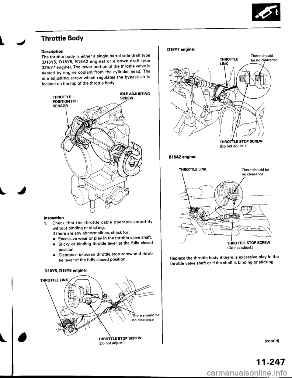
Description
The throttle bodY is either a single-barrel side-draft type
(D16Y5, D16Y8, 816A2 engine) or a down-draft type
(D16Y/ engine). The lower portion ot the throttle valve is
heated by engine coolant from the cylinder head' The
idle adjusting screw which regulates the bypass air is
located on the top of the throttle body
THROTTLEPOS|T|ON lTPlSENSOR
IDLE AD.'USTINGSCREW
t
In3pection
1. Check that the throttle cable operates smoothly
without binding or sticking.
lf there are any abnormalities, check for:
. Excessive wear or play in the throttle valve shaft'
. StickY or binding throttle lever at the fully closed
Position.. Clearance between throttle stop screw and throt-
tle lever at the fully closed position'
D16Y5, Dl6Y8 engine:
THROTTLE STOP SCREW
{Do not adjust.)
Dl6Y7 ongine:
816A2 engins:
THROTTLE LINK
STOP SCREW
THROTTTE STOP SCREW(Do not adjust.)
Replace the throftle body if thsre is excessive play in the
throttle valve shaft or iJ the shaft is binding or sticking'
(cont'd)
11-247
{Do not adjust.)
Page 726 of 2189
Troubleshootin g Procedures
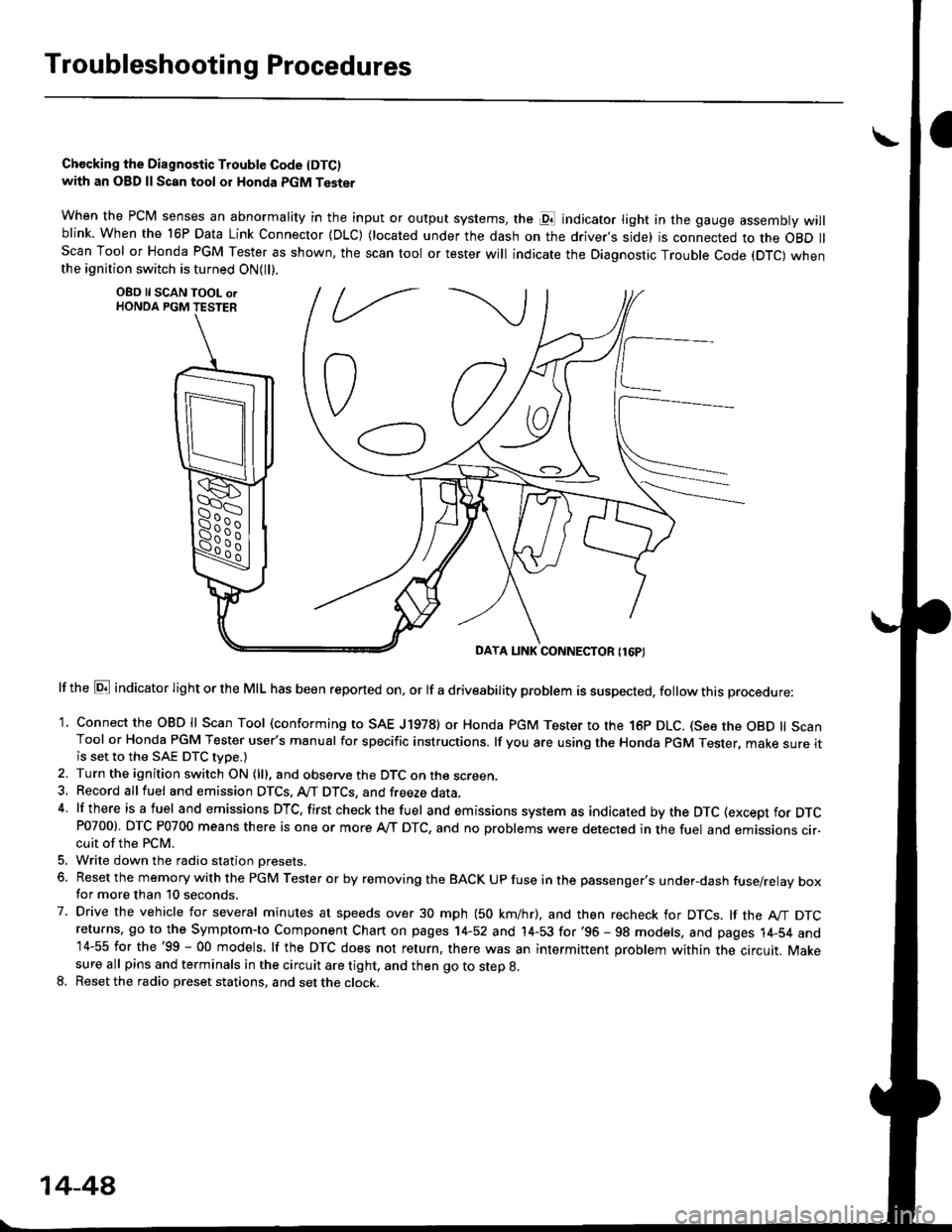
Chccking the Diagnostic Trouble Code IDTC)with an OBD ll Scan tool or Honda PGM Tester
when the PCM senses an abnormality in the input or output systems, the pl indicator light in the gauge assembly willblink. When the 16P Data Link Connector (DLC) (located under the dash on the driver,s side) is connected to the OBD llScan Tool or Honda PGM Tester as shown, the scan tool or tester will indicate the Diagnostic Trouble Code (DTC) whenthe ignition switch is turned ON{ll).
lf the El indicator light or the MIL has been reported on, or lf a driveability problem is suspected, follow this procedure:
1. Connect the OBD ll Scan Tool (conforming to SAE J19781 or Honda PGM Tester to rhe 16p DLC. (See the OBD ll ScanTool or Honda PGM Tester user's manual for specific instructions. lf you are using the Honda PGM Tester, make sure itis set to the SAE DTC type.)
2. Turn the ignition switch ON (lll, and observe the DTC on the screen,3, Record all fuel and emission DTCS, A/T DTCS, and freeze data.4 lf there is a fuel and emissions DTC, first checkthe fuel and emissions system as indicated bythe DTC (except for DTCP0700). DTC P0700 means there is one or more A,/T DTC, and no problems were detected in the fuel and emissions cir-cuit of the PCM.
5. Write down the radio station oresets.
6. Reset the memory with the PGM Tester or by removing the BACK UP fuse in the passenger's under-dash fuse/relay boxfor more than 10 seconds.
7. Drive the vehicle for several minutes at speeds over 30 mph (50 km/hr), and then recheck for DTCS. lf the A"/T DTCreturns, go to the Symptom-to Component Chart on pages 14-52 and 14-53 for'96 - 98 models, and pages 14-54 and14-55 for the'99 - 00 models, lf the DTC does not return, there was an intermittent problem within the circuit. Makesure all pins and terminals in the circuit are tight, and then go to step g.
8. Reset the radio preset stations, and set the clock.
OBD ll SCAN TOOL orHONDA PGM TESTER
DAYA LINK CONNECTOR {16P}
14-44
Page 727 of 2189
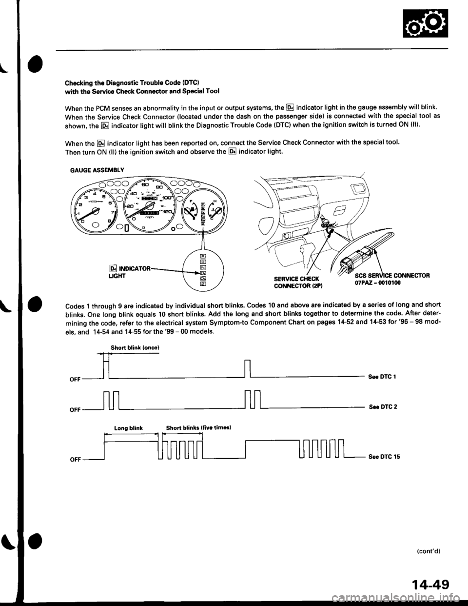
Chocking th€ Diagnostic Trouble Code (DTCI
with the Servico Check Conneqtor and Sp€cialTool
When the PCM senses an abnormality in the input or output systems, the @ indicator light in the gauge assembly will blink
When the Service Check Connector (locat€d under the dash on the passengsr side) is connected with the special tool as
shown, the E indicator light will blink the Diagnostic Trouble Code (DTC) when the ignition switch is turned ON (ll).
When the E indicator light has been reported on, connect the Service Check Connector with the special too'.
Then turn ON (ll) the ignition switch and obssrve the E indicator tight.
CONNECTOBSERVICE CHECKCONNECTOR I2PI07PAZ -0010100
Codes 1 through 9 are indicated by individual short blinks, Codes 10 and above are indicat€d by a sories of long and short
blinks. One long blink equals 1O short blinks. Add the long and short blinks together to determine th€ code. After deter-
mining the code, refer to the electrical system Symptom-to Component Chart on pages 1+52 and 1+53 for'96 - 98 mod-
els, and 14-54 and 14-55 for the '99 - 00 models.
S€r DTC 1
s.. DTC 2
Long blinkShort blink lfiYa tim.!,
S€c DTC 15
(cont'd)
GAUGE ASSEMBLY
Short blink loncel
14-49
Page 729 of 2189
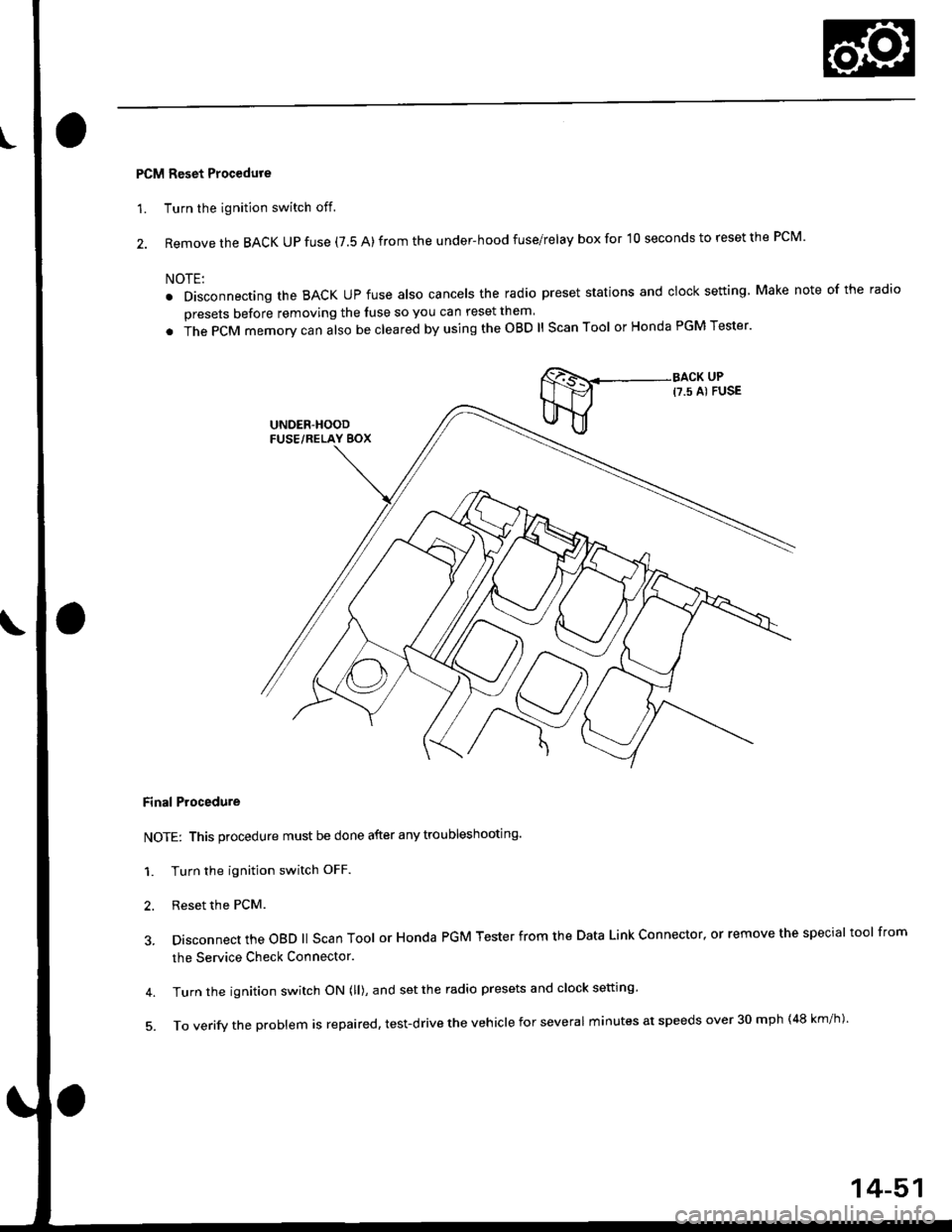
PCM Reset Procedure
1. Turn the ignition switch off.
2. Remove the BACK UP fuse (7.5 A) from the under-hood fuse/relay box for '10 seconds to reset the PCM'
NOTE:
. Disconnecting the BACK UP fuse also cancels the radio preset stations and clock setting Make note of the radio
presets before removing the luse so you can reset them
. in" gCfU memory can also be cleared by using the OBD ll Scan Tool or Honda PGM Tester'
Final Procedure
NOTE: This procedure must be done after any troubleshooting.
1. Turn the ignition switch OFF.
2. Reset the PcM.
3. Disconnect the oBD ll scan Tool or Honda PGM Tester from the Data Link connector, or remove the special tool from
the Service Check Connector.
4. Turn the ignition switch ON (ll), and set the radio presets and clock setting'
5'ToVerifytheprob|emisrepaired,test.drivetheVehic|eforseveralminutesatspeedsover30mph(48km/h).
14-51
Page 730 of 2189
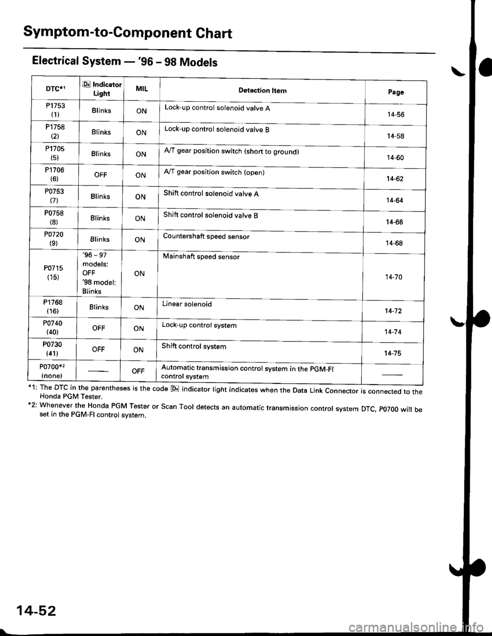
Symptom-to-Component Ghart
Electrical System -'gG - 98 Models
*1: The DTC in the parentheses is the code E indicator light indicates when the Data Link connector is connected to theHonda PGM Tester.*2: Whenever the Honda PGM Tester or Scan Tool detects an automatic transmission control system DTC, p07OO will beset in the PGM-FI control svstem.
DTCIIE Indicaior
LightMILDotection ltemPage
P1753
fl)BlinksONLock-up control solenoid valve A14-56
P1758
\21BlinksONLock-up control solenoid valve B14-58
P1705
(51BlinksONAy'T gear position switch (short to groundl14-60
P1706
(6)OFFONA,/T gear position switch (open)14-62
P0753
l7lBlinksONShift control solenoid valve A14-64
P0758
{8)ElinksONShift control solenoid valve B14-66
POl20
(9)BlinksONCountershaft speed sensor14-68
P0715
{15)
'96 - 97
models:
OFF'98 model:
Blinks
ON
Mainshaft speed sensor
14-70
P1768
{16)BlinksONLinear solenoid't 4-72
P0740
(40)OFFONLock-up control system14-7 4
P0730
(41)OFFONShift control system14-75
P0700*,
(none)Automatic transmission control svstem in the pGM-Fl
control svstem
14-52