ac line HONDA CIVIC 1999 6.G Workshop Manual
[x] Cancel search | Manufacturer: HONDA, Model Year: 1999, Model line: CIVIC, Model: HONDA CIVIC 1999 6.GPages: 2189, PDF Size: 69.39 MB
Page 681 of 2189

Description
The automatic transmission is a 3-element torque converter and a dual-shaft electronically controlled unit which provides
4 soeeds forward and 1 reverse.
Torque Convertel, Geats, and Clutches
The torque converter consists of a pump, turbine and stator, assembled in a single unit. They are connected to the engine
crankshaft so they turn together as a unit as the engine turns. Around the outside of the torque converter is a ring gear
which meshes with the starter pinion when the engine is being started. The entire torque converter assembly seryes as a
flywheel while transmiuing power to the transmission mainshaft.
The transmission has two parallel shafts: the mainshaft and the countershaft. The mainshaft is in Iine with the engine
crankshaft. The mainshaft includes the 1st, 2nd and 4th clutches, gears tor 2nd, 4th, reverse and lst (3rd gear is integral
with the mainshaft, while the reverse gear is integral with the 4th gear). The countershaft includes the 3rd clutch, and
gears for 3rd,2nd, 4th, reverse. 1st and park. The gears on the mainshaft are in constant mesh with those on the counter-
shaft. When certain combinations of gears in transmission are engaged by clutches. power is transmitted from the main-
shaft to the countershaft to provide E, ld, E, and E positions.
Electronic Control
The electronic control svstem consists of the Powertrain Control Module {PCM), sensors, a linear solenoid and four
solenojd valves. Shifting and lock-up are electronically controlled for comtonable driving under all conditions. The PCM is
located below the dashboard, under the front lower panel on the passenger's side
Hydraulic Control
The valve bodies include the main vatve body, the secondary valve body, the regulator valve body, the servo body and the
lock-up valve body through the respective separator plates, They are bolted on the torque converter housang
The main valve body contains the manual valve, the 1-2 shift valve. the 2nd orifice control valve, the CPB {Clutch Pressure
Back-up) valve, the modulator valve. the servo control valve, the relief valve, and ATF pump gears The secondary valve
body contains the 2-3 shift valve. the 3-4 shift valve, the 3-4 orifice control valve, the 4th exhaust valve and the CPC (Clutch
pressure Control) valve. The regulator valve body contains the pressure regulator valve, the torque converter check valve,
the cooler relief valve, and the lock-up control valve. The servo body contains the servo valve which is integrated with the
reverse shift fork, and the accumulators. The lock-up valve body contains the lock-up shift valve and the lock-up timing
valve. The linear solenoid and the shift control solenoid valve Ay'B are bolted on the outside of the transmission housing,
and the lock-up control solenoid valve Ay'B is bolted on the outside of the torque converter housing. Fluid from regulator
passes through the manual valve to the various control valves. The clutches receive fluid from their respective teed pipes
or internal hydraulic circuit.
Shift Control Mechanism
Input from various sensors located throughout the car determines which shift control solenoid valve the PCM will activate
Activating a shift control solenoid valve changes modulator pressure, causing a shift valve to move. This pressurizes a line
to one of the clutches, engaging that clutch and its corresponding gear, The shift control solenoid valves A and B are con-
trolled by the PCM.
Lock-up Mechanism
In ,Dt1 position, in 3rd and 4th. and in E position in 3rd, pressurized fluid is drained from the back of the torque converter
through a fluid passage, causing the lock-up piston to be held against the torque converter cover. As this takes place, the
mainshaft rotates at the same as the engine crankshaft. Together with hydraulic control, the PCM optimizes the timing of
the lock-up mechanism. The lock-up valves control the range of lock-up according to lock-up control solenoid valves A and
B, and linear solenoid. When lock-up control solenoid valves A and B activate, the modulator pressure changes The lock-
up control solenoid valves A and B and the linear solenoid are controlled by the PCM.
(cont'd)
14-3
Page 683 of 2189
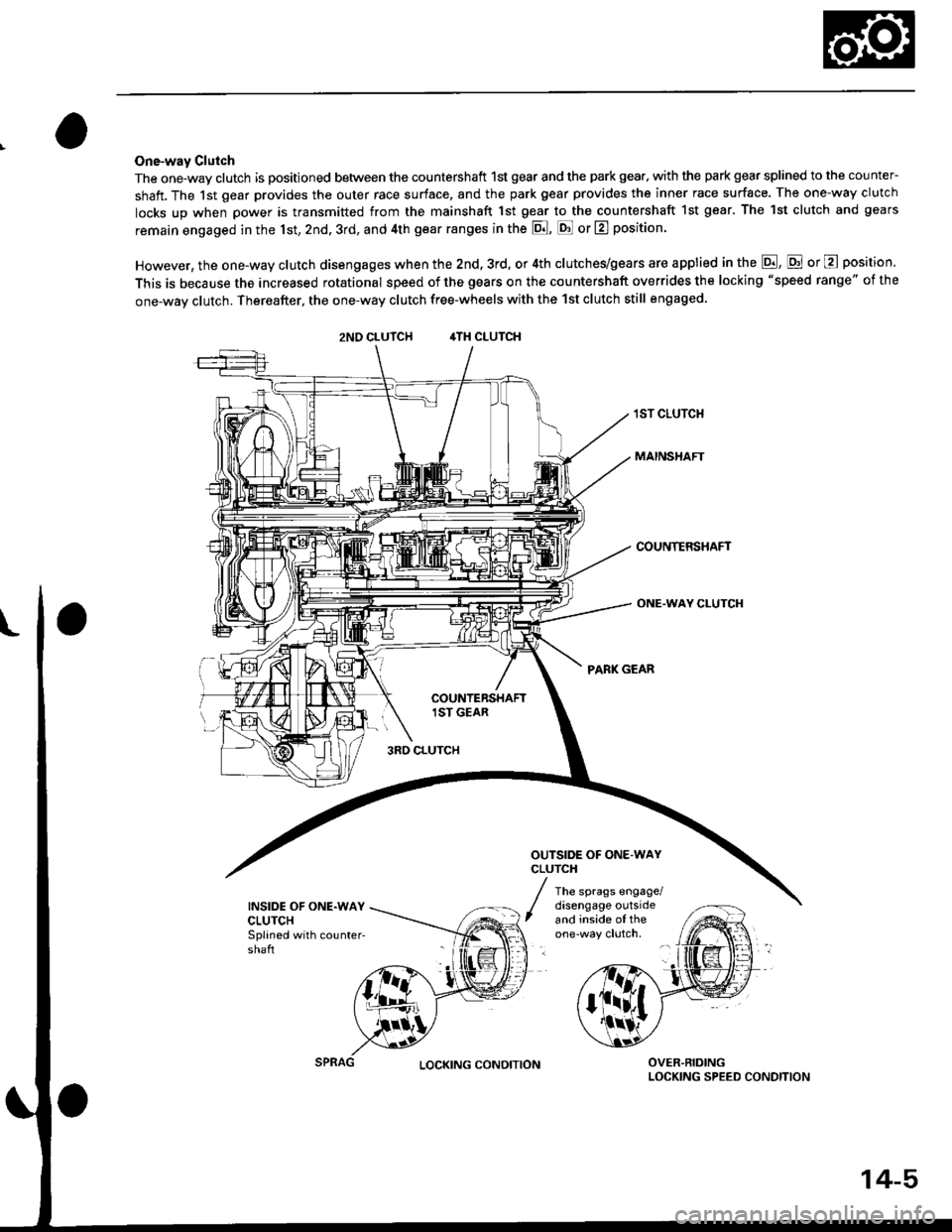
One-way Clulch
The one-way clutch is positioned between the countershaft 1st gear and the park gea., with the park gear splined to the counter-
shatt, The 1st gear provides the outer race surface, and the park gear provides the inner race surface. The one-way clutch
locks up when power is transmitted from the mainshaft 1st gear to thetountershaft 1st gear. The lst clutch and gears
remain engaged in the 1st, 2nd. 3rd, and 4th gear ranges in the p!1, p! or L?l position.
However, the one-way clutch disengages when the 2nd, 3rd, or 4th clutches/gears are applied in the E, E or @ position.
This is because the increased rotational speed of the gears on the countershaft overrides the locking "speed range" of the
one-way clutch. Thereafter, the one-way clutch free-wheels with the 1st clutch still engaged.
zNO CLUTCH ,lTH CLUTCH
1ST CLUTCH
MAINSHAFT
COUNTERSHAFT
ONE.WAY CLUTCH
INSIDE OF ONE.WAYCLUTCHSplaned with countershaft
disengage outsideand inside oI the
3RO CLUTCH
OUTSIDE OF ONE.WAYCLUTCH
PANK GEAR
The sprags engage/
OVER-RIDINGLOCKING SPEED CONDITIONLOCKING CONDITION
14-5
Page 692 of 2189
Description
Electronic Control System (cont'd)
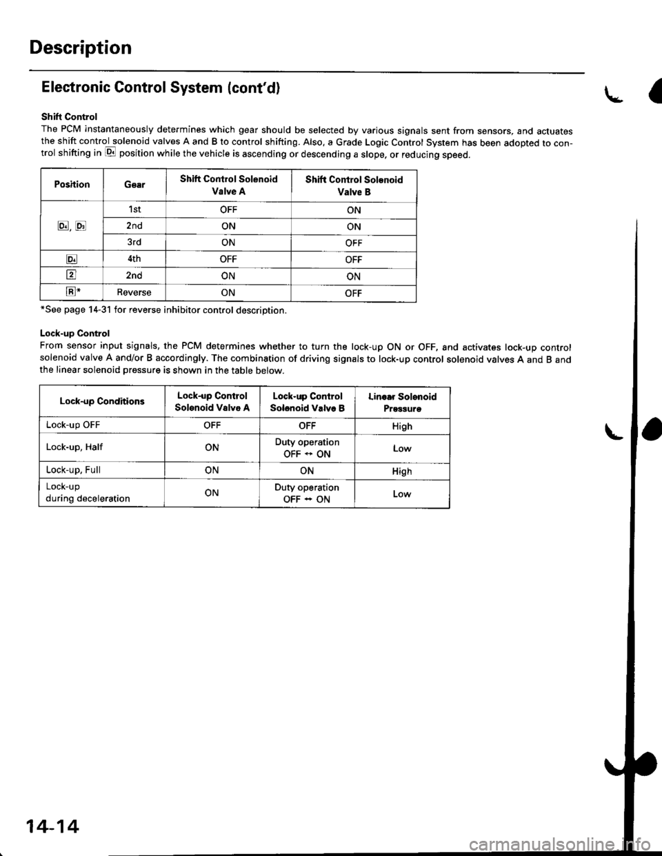
Shift Control
The PCM instantaneously determines which gear should be selected by various signals sent from sensors, and actuatesthe shift control solenoid valves A and B to control shifting. Also. a Grade Logic Control System has been adopted to con-trol shifting in E position while the vehicle is ascending or descending a slope, or reducing speed.
PoshionGearShift Control Solenoid
Vslve A
Shift Control Solenoid
Valve B
8,tr
1stOFFON
2ndONON
3rdONOFF
E4thOFFOFF
tr2ndONON
E-ReverseONOFF
*See page 14-31 for reverse inhibitor control description.
Lock-up Control
From sensor input signals, the PCM determines whether to turn the lock-up ON or OFF, and activates lock-up controlsolenoid valve A and/or B accordingly. The combination of driving signals to lock-up control solenoid valves A and B andthe linear solenoid pressure is shown in the table below.
Lock-up ConditionsLock-up Control
Solenoid Valvo A
Lock-up Control
Solenoid Valve B
Linoar Solonoid
Prggguro
Lock-up OFFOFFOFFHigh
Lock-up, HalfONDuty operation
OFF * ONLow
Lock-up, FullONONHigh
LOCK-Up
during decelerationONDuty operation
OFF - ON
a
14-14
Page 697 of 2189
Hydraulic Control
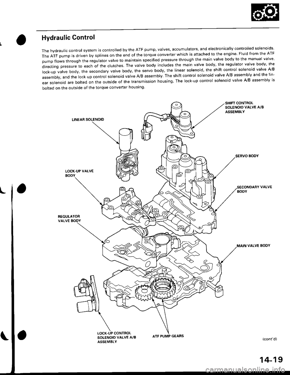
The hydraulic control system is controlled by the ATF pump, valves, accumulators, and electronically controlled solenoids'
TheATFpUmpisdrivenbysp||nesontheendofthetorqueconverterWhichisattachedtotheengine.F|uidfromtheATF
pumpf|owsthroughtheregu|atorva|vetomajntainspecifiedpressurethroughthemainva|vebodytothemanuaIva|ve'
directingpressuretoeachofthec|utches.Theva|vebodyinc|udesthemainvaivebody,theregu|atorvalvebody,the
|ock-upva|vebody,thesecondaryVa|vebody,theservobody,theIinearso|enoid,theshiftcontro|so|enoidva|velVB
assembly, and the lock up control solenoid valve A/B assembly. The shift control solenoid valve Ay'B assembly and the lin-
ear solenoid are bolted on the outside of the transmission housing. The lock-up control solenoid valve A,/B assembly is
bolted on the outside of the torque converter housing
SHIFT CONTROLSOLENOIO VALVE A/8
ASSEMBLY
LINEAR SOLENOID
SERVO BOOY
REGULATORVALVE BODY
VALVE
VALVE BOOY
(cont'd)
CONTROLSOLENOID VALVE A/BASSEMBLY
ATF PUMP GEARS
14-19
Page 700 of 2189
Description
Hydraulic Control (cont'dl
Regulator Valve
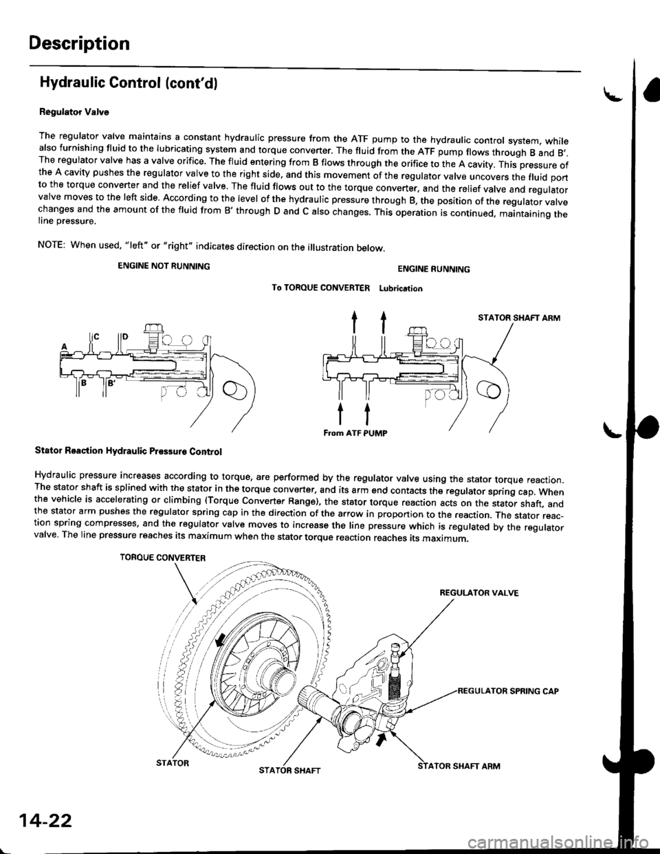
The regulator valve maintains a constant hydraulic pressure from the ATF pump to the hydraulic control system, whitealso furnishing fluid to the lubricating system and torque converter. The fluid from the ATF pump flows through B and 8,.The regulator valve has a valve orifice. The fluid entering from B flows through the orifice to the A cavity. This pressure ofthe A cavity pushes the regulator valve to the right side, and this movement of the regulator valve uncovers the fluid portto the torque converter and the relief valve. The fluid flows out to the torque converter, and the relief valve and regulatorvalve moves to the left side. According to the level of the hydraulic pressure through B, the position of the regutator vatvechanges and the amount of the fluid from B' through D and c also changes. This operation is continued. maantaining theline pressure,
NOTE: When used. "|eft" or "right" indicates direction on the illustration betow.
ENGINE NOT RUNNING
TOROUE CONVERTER
ENGINE RUNNING
To TOROUE CONVERTER Lubrication
Stator Roaction Hydraulic Prossur6 Control
Hydraulic pressure increases according to torque, are performed by the regulator valve using the stator torque reaction.The stator shaft is splined with the stator in the torque converter, and its arm end contacts the regulator sprang cap. whenthe vehicle is accelerating or climbing (Torque Convert€r Range), the stator torque reaction acts on the stator shaft, andthe stator arm pushes the regulator spring cap in the direction of the arrow in proponion to the reaction. Jne stator reac-tion spring compresses, and th€ reoulator valve moves to increase the line pressure which is regulated by the regulatorvalve. The line pressure reaches its maximum when the stator torque reaction reaches its maximum.
STATOR SHAFT ARM
REGULATOR VALVE
14-22
STATORATOR SHAFT ARM
SPRING CAP
Page 702 of 2189
Description
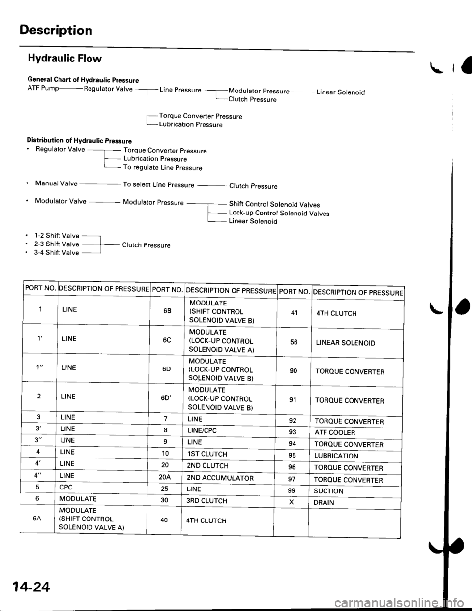
Hydraulic Flow
General Chart ol Hydraulic PressureATF Pump- pegurator varve -_l- Line pressure -f- Modurator pressure - Linear sorenoid
| -Clutch pressure
-Torque Converter pressure
t-Lubrication Pressure
Distribution of Hydraulic Pressur€. Regulator Valve -]- Torque Converter pressure
F_ Lubrication pressure
i- To regulate Line pressure
. Manual valve _ To select Line pressure _ clutch pressure
' Modulator Valve i/odulator pressure _ ___f_ Shift Control Solenoid Valves
F_ Lock_up Control Solenoid ValvesL_ Linear Solenoid
. 1-2 Shift Valve - l. 2-3 Shift Valve - 1- Ctutch pressure. 3-4 Shift Valve
lra
PORT NO.DESCRIPTION OF PRESSUREPORT NO.DESCRIPTION OF PRESSUREPORT NO.DESCRIPTION OF PRESSURE
1LINE6B
MODULATE(SHIFT CONTROL
SOLENOID VALVE B)
414TH CLUTCH
LINEMODULATE(LOCK-UP CONTROL
SOLENOID VALVE A)
56LINEAR SOLENOID
LINE6D
MODULATE(LOCK-UP CONTROL
SOLENOID VALVE B)
90TOROUE CONVEBTER
2LINE6D'
MODULATE
(LOCK-UP CONTROL
SOLENOID VALVE B)
91TOROUE CONVERTER
LINE7LINE92TOROUE CONVERTERLINE8LINE/CPC93ATF COOLER3"LINE9LINE94TOROUE CONVERTER4LIN E'101ST CLUTCH95LUBRICATION
LINE202ND CLUTCHYOTOROUE CONVERTERLINE20A2ND ACCUMULATOR97TOROUE CONVERTER5LINE99SUCTION
MODULATE303RD CLUTCHXDRAIN
6A
MODULATE(SHIFT CONTROL
SOLENOID VALVE A)
404TH CLUTCH
14-24
Page 703 of 2189
\
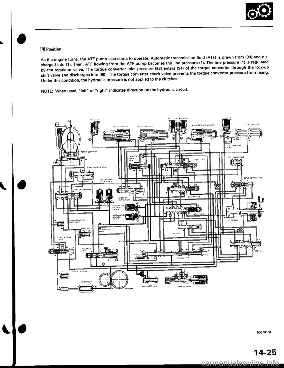
@ Position
As the engine turns, the ATF pump also starts to operate, Automatic transmission fluid (ATF) is drawn from (99) and dis-
charged into (1). Then, ATF flowing from the ATF pump becomes the line pressure (1). The line pressure (1) is regulated
by the regulator valve. The torque conv€rter inlet pressure (92) enters (94) of the torque converter through the lock-up
shift valve and discharges into (901. The torque converter ch€ck valve prevents the torque converter pressure from rising'
Under this condition, the hydraulic pressure is not applied to the clutches'
NOTE: When used, "1eft" or "right" indicates direction on the hydraulic circuit'
14-25
Page 704 of 2189
Description
Hydraulic Flow (cont'd)
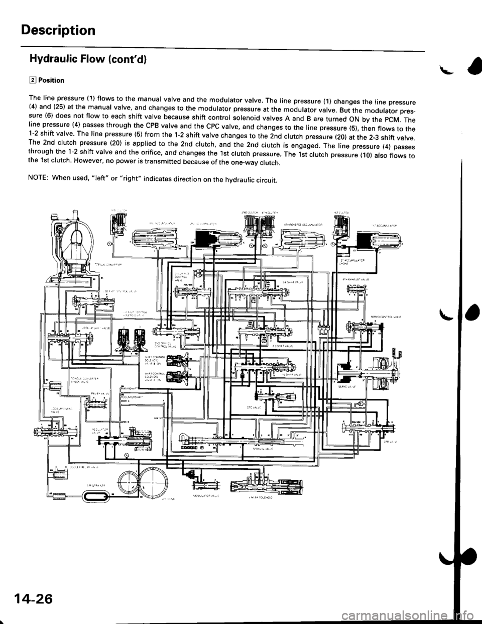
L?j Position
The line pressure (1) flows to the manual valve and the modulator valve. The line pressure (1) changes the trne pressure(4) and (25) at the manual valve. and changes to the modulator pressure at the modulator valve. But the moourator pres-sure (6) does not flow to each shift valve because shift control solenoid valves A and B are turned oN by the pcM. Theline pressure (4) passes through the cPB valve and the cPc valve. and changes to the line pressure (s), th;n flows to the1-2 shift valve. The line pressure {S) from the l-2 shift valve changes to the 2nd clutch pressure (20) at the 2-3 shift valve.The 2nd clutch pressure (20) is applied to the 2nd clutch. and the 2nd clutch is engaged. The line pressure (4) passesthrough the 1-2 shift valve and the orifice, and changes the lst clutch pressure, The 1st clutch pressure (10) atso flows tothe 1st clutch. However, no power is transmitted because of the one_way clutch.
NOTE: When used, "Ieft" or "right" indicates direction on the hvdraulic circuit.
14-26
Page 705 of 2189
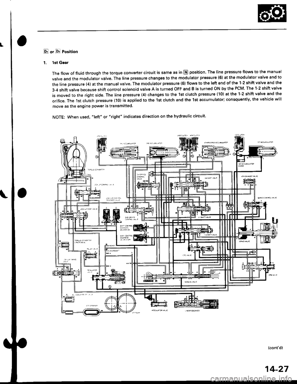
E! or l8! Position
1. lst Gear
The flow of fluid through the torque converter circuit is same as in E position, The line pressure tlows to the manual
valve and the modulator valve. The line pressure changes to the modulator pr€ssure (6) at the modulator valve and to
the line pressure (4) at the manual valve. The modulator pressure (61 flows to the lsft end of the 1-2 shift valve and the
3-4 shift valve because shift control solenoid valve A is turned OFF and B is turned ON by the PCM. The 1-2 shift valve
is moved to the right side. The line pressure (4) changes to the lst clutch pressure (10) at the 1-2 shift valve and the
oritice. The lst clutch pressure (10) is applied to the 1st clutch and tho 1st accumulator; consquently, the vehicle will
move as the engine power is transmitted.
NOTE: When used, "|eft" or "right" indicates direction on the hydraulic circuit'
(cont'd)
14-27
Page 706 of 2189
Description
Hydraulic Flow (cont'd)
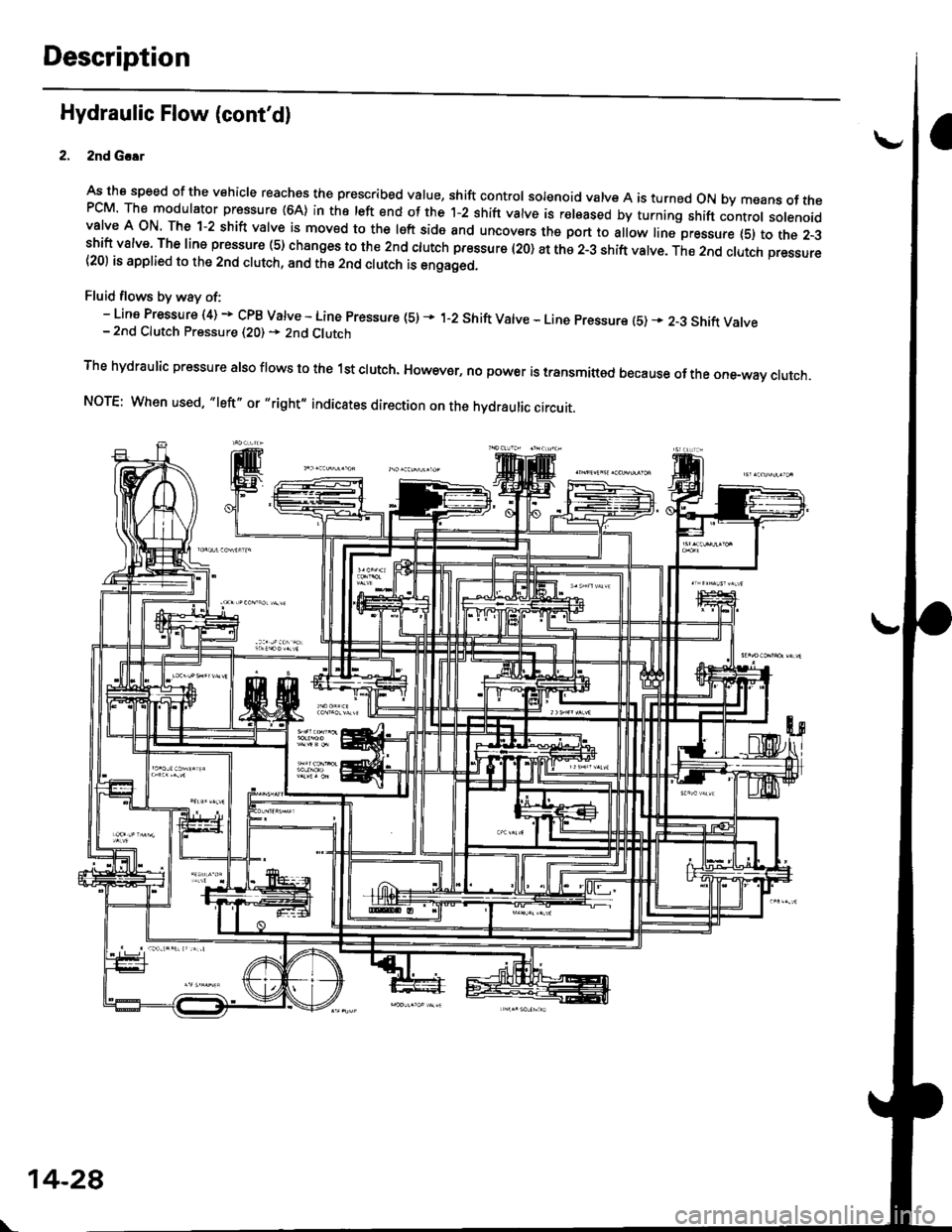
2nd G.!r
As tha speed of the vehicle reaches the prescribed value, shift control solenoid valve A is turned oN by means of thePCM The modulator pressure {64} in the left end of the 1-2 shift valve is r€leased by turning shift controt sotenoidvalve A oN The 1-2 shift valve is moved to the left side and uncovers the port to allow line pressure {5) to the z-3shift valve. The line pressure (5) changes to the 2nd ctutch pfessure l2O) at the 2-3 shift valve. The 2nd clutch pressure(20) is applied to the 2nd clutch, and the 2nd clutch is engaged.
Fluid flows by way of:- Line Pressure (4) + cPB varve - Line pressure (s) * 'r-2 shift varve - Line pressure (5) * 2-3 shift varve- 2nd Clutch Pressure (20) + 2nd Clutch
The hydraulic pressure also flows to the 1st clutch. However, no power is transmittod because of the one-way ctutch.
NOTE: When used, "|eft" or ,,right,, indicates direction on the hydraulic circuit.
\-
14-28