troubleshooting HONDA CIVIC 1999 6.G Workshop Manual
[x] Cancel search | Manufacturer: HONDA, Model Year: 1999, Model line: CIVIC, Model: HONDA CIVIC 1999 6.GPages: 2189, PDF Size: 69.39 MB
Page 1804 of 2189
Troubleshooting
DTC 9-2 (cont'dl
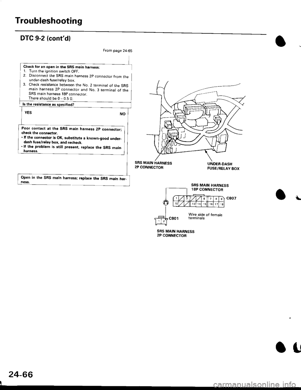
2- Disconnect the SRS rnain harness 2p connector lrom theunder-dash fuse/relay box.3- Check resistance between the No. 2 terminal of the SRSmain harness 2P connecior and No. 3 terminal of theSFS main harness 18P connector_
Poor contact at the SRS main ha.ness 2p connector;check the connecto... lf the connector is Ol(, sub3titute a known-good under-dash tuse/r€lay box, and recheck.'lt tho problem is still present, replece the SRS main
Open in the SBS main harness; replace the SRS main har_ness,
SRS MAIN HARNESS2P CONNECTOR
24-66
I
\
From page 24-65
Chock tor an open in th€ SRS main hern€ss:1. Turn the ignition switch OFF.
There should be 0 0.5 0
SRS MAIN
SRS MAIN HARNESS18P CONNECTOR
o!
Page 1821 of 2189
How To Use This Manual
Power Distribution Schematics (cont'd)
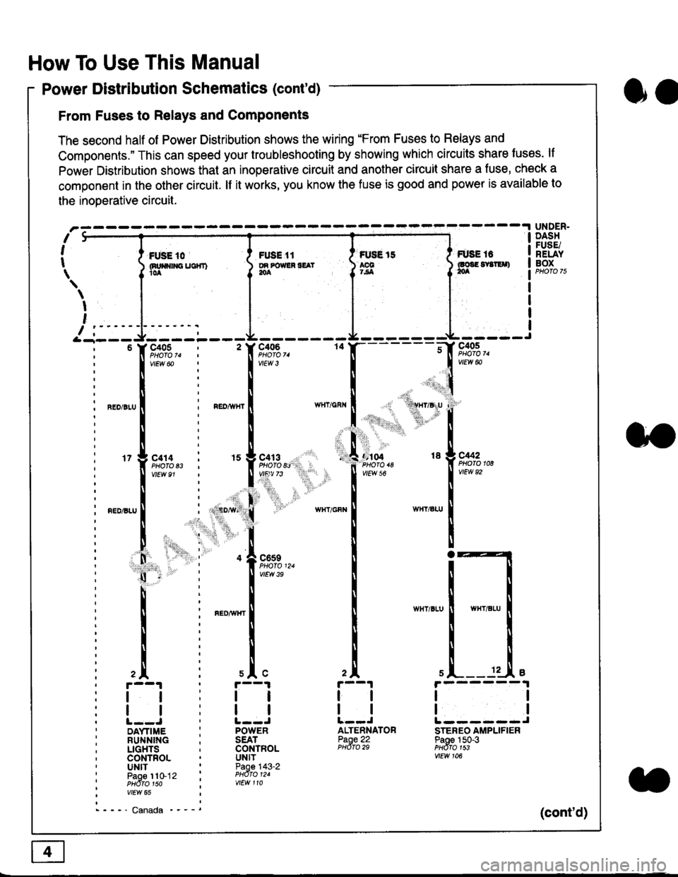
From Fuses to Relays and Components
The second half of Power Distribution shows the wiring "From Fuses to Relays and
Components." This can speed your troubleshooting by showing which circuits share luses. lf
Power Distribution shows thal an inoperative circuit and another circuit share a fuse, check a
component in the other circuit. lf it works, you know the fuse is good and power is available to
the inoDerative circuit.
oa
UNDER.DASHFUSE/RELAYBOXI i *. to i ru..'.' l * tt I tust tt
){nuo$rouc}rr) }g*"""' }tS }ff***,
\
I
,
I-- - ----\&- -----J-------ir
9,s9:,.,
,.,'li"'"rr' ' 'rll$vryglu
:
]:l. ,' "'':r.,
,:ti. .:1,,.,
*_lu*'.
'71ffi"�
- -t**,-
vtEw &
04 18 g C442
2A
tl
12 .L e
tl
ALTENNATORPaoe 22PHdro 29
ll
tlL------JSTEREO AMPLIFIERPaoe 150-3PHdfo 1s3vtEw 106
121
'f,"c;93,. : '� f,t'ffi
lv'Ew6o ! 1,.",
l:lN'll
^.o,r.u I i ".o,*", I
l:t
l,l
u*,.11,2", i "l9*',g
11""" : l*'-
l:lnEDisLu
|
; . ED,w' (
I'lP:ll
! " : .1".,9t3
q - '
I v'Ew3e
h;ll
l:ll
I : FED^rir{r
i
l:i
tii
,.L i slc
r--1 : r--1
tt:ll
ltlllt--J ' l--JDAYTIME : POWERRUNNING ; SEATLIGHTS . CONTROLCONTROL . UNITUNIT ' Paoe 143-2paoe 1to-j2 t PHdro t2.PHdTo 1so i wEw 110vtEw 65
- - -' Canada '_ _ _(cont'd)
Page 1828 of 2189
Five-Step Troubleshooting
L Verify The Complaint
Turn on all the components in the problem
circuil lo check the accuracy of the customer
complaint. Note the symptoms. Do not begin
disassembly or testing until you have
narrowed down the problem area.
2. Analyze The Schematic
Look up the schematic for the problem
circuit. Determine how the circuit is
supposed to work by tracing the current
paths lrom the power source through the
circuit components to ground. Also, trace
circuits that share wiring with the problem
circuit. The names of circuits that share the
same fuse, ground, or switch, and so on, are
referred to in each circuit schematic. Try to
operate any shared circuits you didn't check
in step 1 . lt the shared circuits work, the
shared wiring is OK, and the cause must be
in the wiring used only by the problem
circuit. lf several circuits fail at the same
time, the fuse or ground is a likely cause.
Based on the symptoms and your
understanding of the circuit's operation,
identify one or more possible causes.
3. lsolate The Problem By Testing The Circuit
Make circuit tests to check the diagnosis
you made in step 2. Keep in mind that a
logical, simple procedure is the key to
efficient troubleshooting. Test for the most
likely cause of failure first. Try to make tests
at points that are easily accessible.
4. Fix The Problem
Once the specific problem is identified,
make the repair. Be sure to use proper tools
and safe procedures.
5. Make Sure The Circuit Works
Turn on all components in the repaired
circuit in all modes to make sure you've
fixed the entire problem. ll the problem was
a blown fuse, be sure to test all of the
circuits on that fuse. Make sure no new
problems turn up and the original problem
does not recur.
Test Equipment
Most circuits include solid-state devices.
Test the voltages in these circuits only with
a 1o-megaohm or higher impedance digital
mUltimeter. Never use a test light or analog
meter on circuits that contain solid-state
devices. Damage to the devices may result.
Test Light and DVOM
On circuits without solid-state devices, use a
test light to check for voltage. A test light is
made up of a 12 volt bulb with a pair of leads
attached. After grounding one lead, touch the
other lead to various points along the circuit
where voltage should be present. The bulb
will go on if there is voltage at the point being
tested. lf you need to know how much
voltage is present, use a digital
volVohmmeter (DVOM).
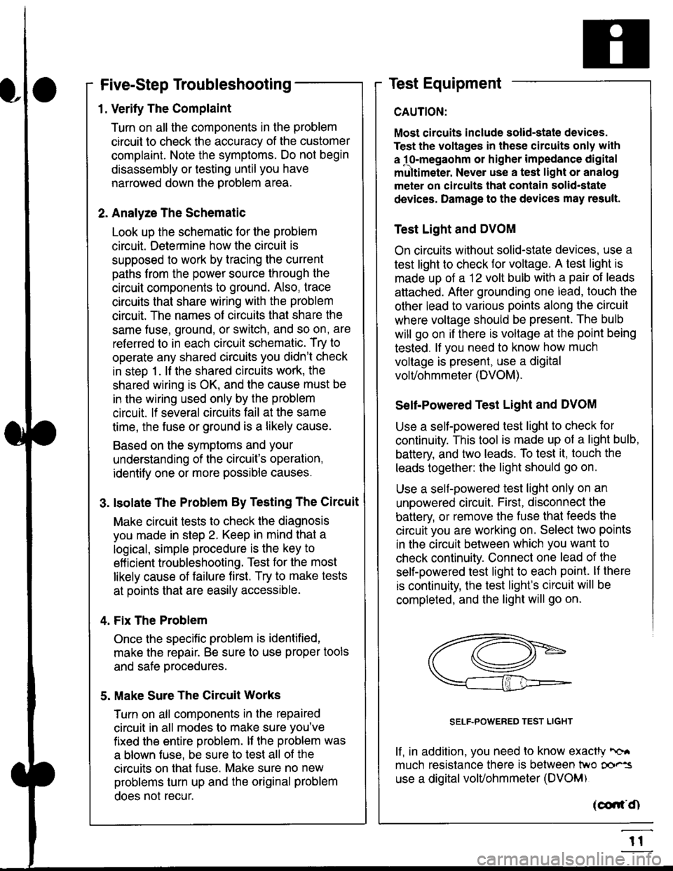
Self-Powered Test Light and DVOM
Use a self-powered test light to check for
continuity. This tool is made up of a light bulb,
battery, and tlvo leads. To test it, touch the
leads together: the light should go on.
Use a self-powered test light only on an
unoowered circuit. First, disconnect the
battery, or remove the fuse that feeds the
circuit you are working on. Select two points
in the circuit belween which you want to
check continuity. Connecl one lead of the
self-powered test light to each point. lf there
is continuity, the test light's circuit will be
completed, and the light will go on.
SELF-POWERED TEST LIGHT
lf, in addition, you need lo know exacW hc'.
much resistance there is between two oo'^=
use a digital volUohmmeter (DVOM)
acdrt'Cn
t1
Page 1829 of 2189
In the "OHMS" range, the DVOM will measure
resistance between two points along a circuit.
Low resistance means good continuity.
Diodes and solid-state devices in a circuit can
make a DVOM give a false reading. To check
a reading, reverse the leads, and take a
second reading. lf the readings differ, the
component is affecting lhe measurement.
Jumper Wire
Use a jumper wire to bypass an open circuit.
A iumper wire is made up ot an in-line fuse
holder connected to a set of test leads. lt
should have a five amoere fuse. Never
connect a jumper wire across a short circuit.
The direct battery short will blow the fuse.
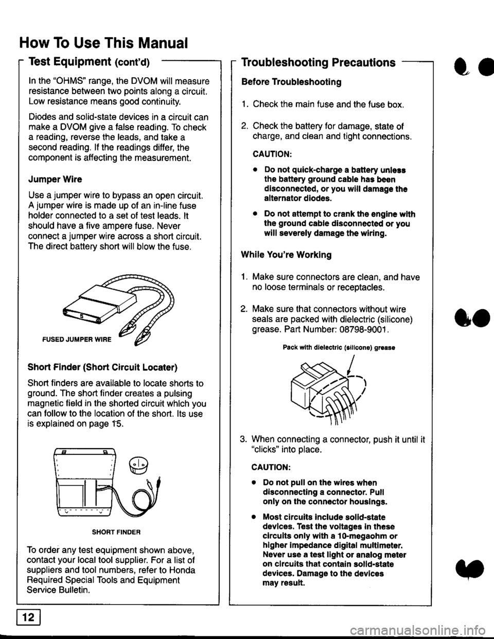
Short Finder (Short Circuit Locater)
Short finders are available to locale shorts to
ground. The short tinder creates a pulsing
magnetic field in the shorted circuit whlch you
can follow to the location of the short. lts use
is explained on page 15.
SHORT FINDER
To ordei any test equipment shown above,
contact your local tool supplier. For a list of
suppliers and tool numbers, refer to Honda
Required Special Tools and Equipment
Service Bulletin.
How To Use This Manual
Test Equipment (cont'd)
oa
Troubleshooting Precautions
Before Troubleshooting
1. Check the main fuse and the fuse box.
2. Check the battery for damage, state of
charge, and clean and tight connections.
CAUTION:
. Do not quick-charge a battery unlers
the battery ground cable has been
disconnected, or you will damage the
alternator diodes.
. Do not attempt to crank the engine wlth
the ground cable disconnected or you
will severely damage the wiring.
While You're Working
1. Make sure connectors are clean, and have
no loose terminals or receptacles.
2. Make sure lhat connectors without wire
seals are packed with dielectric (silicone)
grease. Part Number: 08798-9001 .
Pack wllh dlelectrlc (sillcons) greass
When connecting a connector, push it until it"clicks" into place.
Do not pull on the wires when
disconnecting a connector. Pull
only on the connector houslngs.
Most circuits Include solid-state
devlces. Test the voltages In these
circuits only with a lo-megaohm or
higher impedance digital multlm6ter.
Never use a test light or analog meter
on chcuits that contain solld-state
devices. Damage to the devices
may result.
oo
Page 1830 of 2189
Troubleshooting Tests
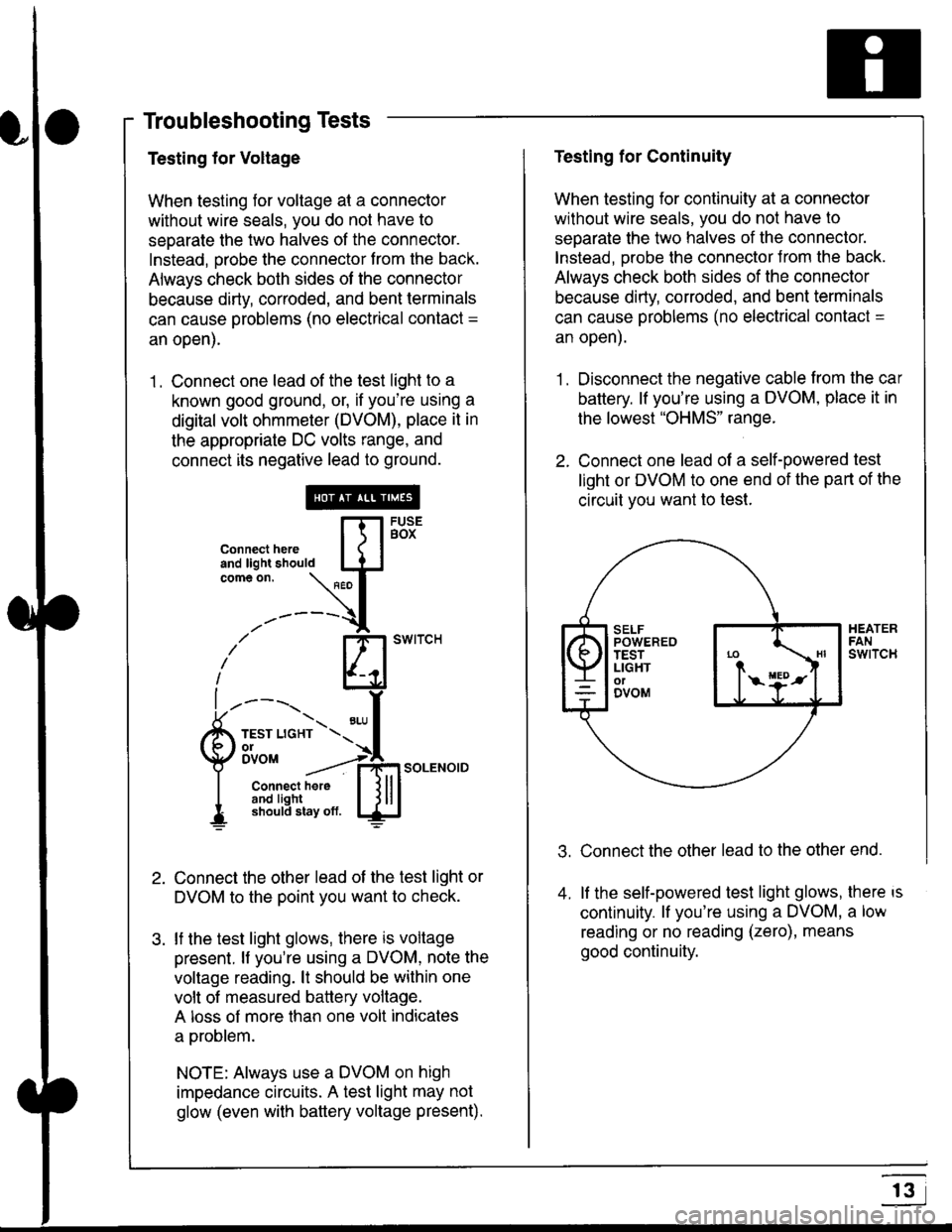
Testing for Voltage
When testing for voltage at a connector
without wire seals, you do not have to
seoarate the two halves of the connector.
Instead, probe the connector from the back.
Always check both sides of the connector
because dirty, corroded, and bent terminals
can cause problems (no electrical contact =
an open).
1 . Connect one lead of the test light to a
known good ground, or, if you're using a
digital volt ohmmeter (DVOM), place it in
the appropriate DC volts range, and
connect its negative lead to ground.
Connect the other lead of the test light or
DVOM to the point you want to check.
lf the test light glows, there is voltage
present. lf you're using a DVOM, note the
voltage reading. lt should be within one
volt of measured battery voltage.
A loss of more than one volt indicates
a problem.
NOTE: Always use a DVOM on high
impedance circuits. A test light may not
glow (even with baftery voltage present).
connecthere [fl5tst-tand light should IJJcomeon.
\" I
------{
/' BT swrrcH
lhl
l ----., I
6m""*soLENo,DI connect here I { lll
I 3#Ji8iL,* lj!!J
Testing for Continuity
When testing for continuity at a connector
without wire seals, you do not have to
separate the two halves of the connector.
lnstead. Drobe the connector Jrom the back.
Always check both sides of the connector
because dirty, conoded, and bent terminals
can cause problems (no electrical contacl =
an open).
1. Disconnect the negative cable from the car
battery. lf you're using a DVOM, place it in
the lowest "OHMS" range.
2. Connect one lead of a self-powered test
light or DVOM to one end of the part of the
circuit vou want lo test.
Connect the other lead to the other end.
lf the self-powered test light glows, there is
continuity. lf you're using a DVOM, a low
reading or no reading (zero), means
good continuity.
.t.
A
r3
Page 1831 of 2189
How To Use This Manual
Troubleshooting Tests
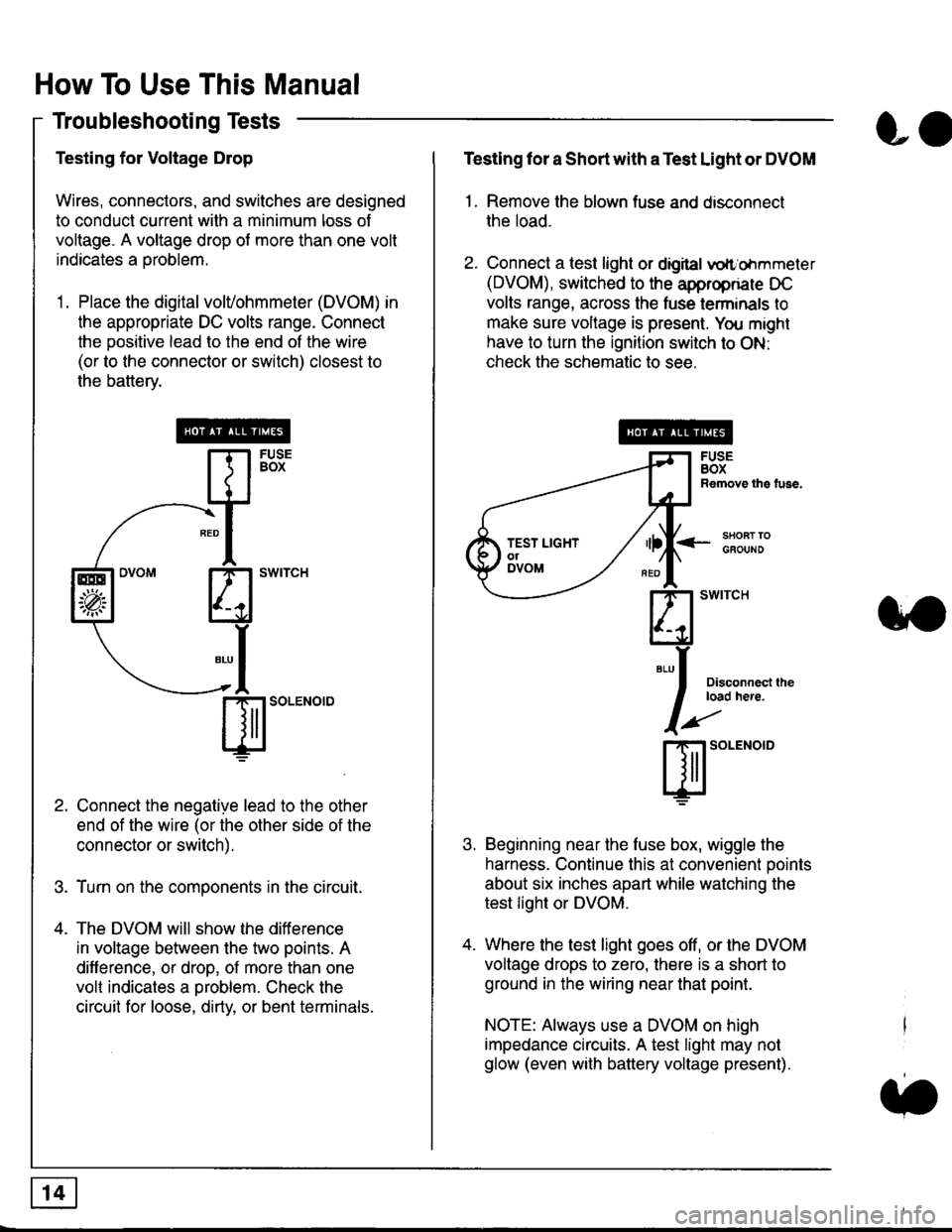
Testing for Voltage Drop
Wires, connectors, and switches are designed
to conduct current wilh a minimum loss of
voltage. A voltage drop of more than one volt
indicates a Droblem.
'1. Place the digital volVohmmeter (DVOM) in
the appropriate DC volts range. Connect
the positive lead to the end of the wire
(or to the connector or switch) closest to
the bafterv.
Connect the negative lead to the other
end of the wire (or the other side of the
connector or switch).
Turn on the components in the circuit.
The DVOM will show the difference
in voltage between the two points. A
difference, or drop, of more than one
volt indicates a oroblem. Check the
circuit for loose, dirty, or bent terminals.
co
Testing lor a Short with a Test Light or DVOM
1. Remove the blown fuse and disconnect
the load.
2. Connect a test light or digital
oltr'ohmmeter
(DVOM), switched to the appropnare DC
volts range, across the tuse lerminals to
make sure voltage is present. You might
have to turn the ignition switch to ON:
check the schematic to see.
<-s80RT TOGFOUNO
Disconnecl lheload here.
Beginning near the luse box, wiggle the
harness. Continue this at convenient ooints
about six inches apart while watching the
test light or DVOM.
Where the test light goes off, or the DVOM
voltage drops to zero, there is a short to
ground in the wiring near that point.
NOTE: Always use a DVOM on high
impedance circuits. A test light may not
glow (even with battery voltage present).
3'�'
ffito.'"o'o
.t.
TEST LIGHTolDVOM
Page 1833 of 2189
How To Use This Manual
Troubleshooting Tests (cont'd)
4. Turn on the short finder. This creates a
pulsing magnetic field around the wiring
between the fuse box and the short.
5. Beginning at the fuse box, slowly move
the short finder along the circuit wiring.
The meter will show current Dulses
through sheet metal and body trim. As
long as the meter is between the fuse and
lhe short, the needle will move with each
current pulse. Once you move the meter
past the point of the short, the needle will
stop moving. Check the wiring and
connectors in this area to locate the cause
of the short.
co
Page 1917 of 2189
- How the Gircuit Works
With the ignition switch in ON (ll) or START (lll),
battery voltage is supplied through fuse 15 and
the BLI(WHT and BLK/YEL wire to the vehicle
speed sensor (VSS). The sensor is grounded by
the BLK wire to G1 01 . The speedometer and
other control units in the circuit supply about 5
volts to the BLU/WHT wire. The vehicle soeed
sensor (VSS) intermittently grounds the
BLUMHT wire which generates a pulsed signal
in it. The number of pulses per minute
increases/decreasos with the soeed of the car.
Reter to th€ Service Manual (Section 23, Electrical)
tor specific tosts or troubleshooting procedures.
33-1
Page 1922 of 2189
Gruise Control (cont'd)
- How the Circuit Works
The cruise control system uses mechanical and
electrical devices to maintain the car's sDeed at a
setting selected by the driver.
System Description
The cruise control unit receives command signals
from the crurse control main switch and the cruise
control SeVResume switch. With the ignition switch
in ON (ll) or START (lll), voltage is provided to the
cruise control main switch through fuse 14. When
you push the switch to ON, power is provided to the
cruise control unit and the brake switch.
The cruise control unit receives information about
operating conditions from the brake switch, the
vehicle speed sensor (VSS), and the clutch switch
(manual transmission) or the A,/T gear position
switch (automatic transmission). The cruise control
unit then sends signals to the cruise control actuator
which regulates the throttle position to maintain the
selected speed. The conlrol unit compares the
actual speed of the car to the selected speed. The
control unit then uses the result of that comoarison
to open or close the throttle.
The brake switch releases the system's control of
the throttle at the instant you press on the brake
pedal. The switch sends a signal to the control unit
by removing power from the normally closed brake
input (GRY wire), and providing power at the
normally open brake input (GRN/vVHT wire). The
control unit responds by allowing the throttle to
close. The clutch switch or the A,/T gear position
switch sends a "disengage" signal to the control unit
that also allows the throttle to close.
The cruise control system will set and automatically
maintain any speed above 25 mph (40 km/h). To set
it, make sure the main switch is on and the switch
indicator is on. Then, after reaching the desired
speed, press the SET switch. This sends a "set"
signal to the cruise control unit which, in turn,
controls the cruise control actuator to maintain the
set speed.
When you push the SET switch and the cruise
control system is on, the "cruise control" ON
indicator lights up.
34-4
(
You can cancel the cruise control system by
turning the main switch off . This removes power to
the control unit and erases the set speed from
memory. lf the system is disengaged temporarily
by the brake switch, or clutch switch, and the car's
speed is still above 25 mph, press the resume
switch: the car will automatically return to the
previously set speed.
For gradual acceleration without pressing the
accelerator pedal, push the RESUME switch and
hold it there. This will send an "acceleration" signal
to the control unit. When you release the switch, the
system will be reprogrammed for the new speed. To
slow the car down. oush the SET switch in and hold
it there. This sends a "deceleration" signal to the
control unit, causing the car to coast. When the
desired speed is reached, release the SET switch.
This reprograms the system tor the new speed.
Refer to the Service Manual (Section 23, Electrical)
tor specific tests or troubleshooting procedures.
(
a
Page 1945 of 2189
- How the Circuit Works
The anti-lock brake system (ABS) prevents locking
of the wheels as a result of heavy braking and/or
poor lraction. A vehicle with locked wheels cannot
be steered. The anti-lock brake system controls the
application of the brakes, allowing the driver to
maintain control of the steering.
Under anti-lock conditions, the antilock brake
system (ABS) modulates the pressure of the brake
tluid to each brake caliper. This system is a four
channel system: the pressure at each caliper is
controlled independently of the pressure al any
other caliper. Whenever a wheel is likely to lock
dunng braking, the anti-lock brake system
modulates the brake oressure at that wheel. When
the brake pressure is reduced to the point where
there is no longer any possibility of wheel locking,
the system returns to the conventional braking
system mode of operation.
Battery voltage is applied at all times through fuse
63 to the ABS control unit. When the ignition switch
is in ON (ll), battery voltage is supplied to the
control unit through fuse 16. The control unit is case
grounded. Inputs are received from the brake switch
and the individual wheel sensors located at each
wheel. The ABS control unit uses these inputs to
control the modulator solenoid unit. The solenoids
adjust the hydraulic pressure applied to each
calioer.
The ABS control unit has a self-diagnosis function.
When the control unit detects a fault, it turns on the"ABS" indicator and disables the anti-lock brake
system. lf the fault is not in the conventional braking
system, the brakes will continue to operate normally
but without the anti-lock feature.
Refer to the Service Manual (Section '19,
Anti-Lock Brake System) for specific tests or
troubleshooting procedures.
44-3