boot HONDA CIVIC 1999 6.G Owner's Manual
[x] Cancel search | Manufacturer: HONDA, Model Year: 1999, Model line: CIVIC, Model: HONDA CIVIC 1999 6.GPages: 2189, PDF Size: 69.39 MB
Page 1045 of 2189
Driveshafts
Reassembly (cont'dl
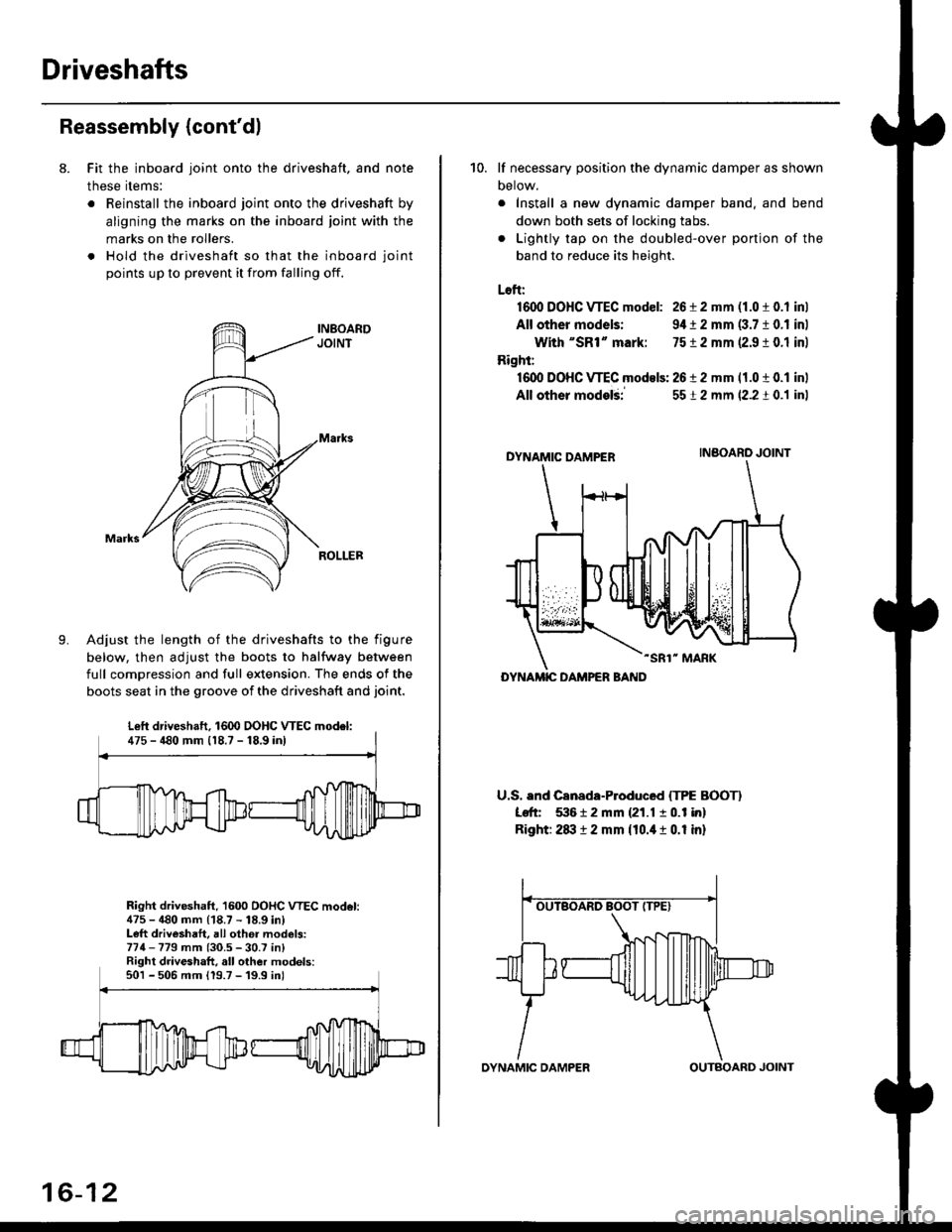
8. Fit the inboard joint onto the driveshaft, and note
these items:
. Reinstall the inboard joint onto the driveshaft by
aligning the marks on the inboard joint with the
marks on the rollers.
. Hold the driveshaft so that the inboard joint
points up to prevent it from falling off.
Adjust the length of the driveshafts to the figure
below, then adjust the boots to halfway between
full comDression and full extension. The ends of the
boots seat in the groove of the driveshaft and joint.
Right driveshaft, 1600 OOHC VTEC model:475 - 480 mm (18.7 - 18.9 in)Left driveshaft, all othei models:774-779 mm (30.5 - 30.7 in)Right driveshaft, all other models:501 - 506 mm 119.7 -'19.9 inl
Left driveshaft. 1600 DOHC WEC model:475 - 480 mm 118.7 - 18,9 inl
16-12
OYNAMIC DAMPEROUTBOARD JOINT
10. lf necessary position the dynamic damper as shown
Detow.
. Install a new dynamic damper band. and bend
down both sets of locking tabs.
. Lightly tap on the doubled-over ponjon of the
band to reduce its height.
Loft:
1600 DOHC VTEC model: 26 i 2 mm (1.0 t 0.1 inl
All other models: 9,1t 2 mm (3.7 10.1 inl
With "SR1" mark: 7512 mm 12.9 ! 0.1 inl
Right:
16dl DOHC VTEC models: 2612 mm 11.0 t 0.1 inl
All other modelii
DYNAMIC DAMPER
-SR1" MARK
U.S. and Canada-Produced ITPE BOOTI
Left 53612 mm {21.1 10.1 in}
Right: 2txt 12 mm {10.it 1 0.1 in}
5512 mm (2.2 t 0.1 inl
INBOARO JOINT
DYNAMIC DAMPER BAND
Page 1046 of 2189
l.
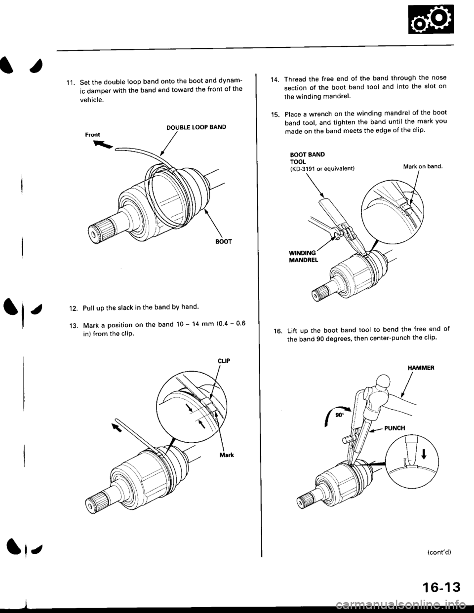
11. Set the double loop band onto the boot and dynam-
ic damper with the band end toward the front ot the
vehicle.
LOOP BANO
Pull up the slack in the band bY hand
Mark a position on the band 10 - 14 mm {0 4 - 0 6
in) from the cliP.
DOUBLE
,
1')
13.
CLIP
Ip
14.
15.
Thread the free end of the band through the nose
section of the boot band tool and into the slot on
the winding mandrel.
Place a wrench on the winding mandrel of the boot
band tool, and tighten the band until the mark you
made on the band meets the edge of the clip.
Mark on band.
Lift up the boot band tool to bend the free end
the band 90 degrees, then center-punch the clip'16.
(cont'd)
16-13
(KD-3191 or equivalent)
HAMMER
Page 1047 of 2189
Driveshafts
17.
Reassembly (cont'dl
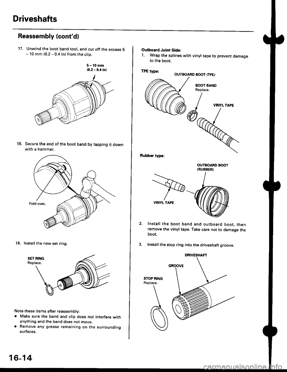
Unwind the boot band tool, and cut off the excess 5- 10 mm (0.2 - 0.4 in) from the clip.
5-10mm10.2 - 0.a inl
Secure the end of the boot band by tapping it downwith a hammer,
19. Installthe new set ring,
18.
Note these items after reassembly:. Make sure the band and clip does notanything and the band does not move.a Remove any grease remaining on thesurfaces.
interfere with
su rrou nding
16-14
Outboard Joint Sid.:
1. Wrap the splines with vinyl tape to prevent damageto the boot.
TPE tvDe:-. OUTBOARO BOOT ITPE)
BOOT BANDReplac€,
Rubber typ.:
Install the boot band and outboard boot, thenremove the vinyl tape. Take care not to damage theboot,
Install the stop ring into the driv€shaft groove.
DRIVESHAFT
>VINYL TAPE
VINYL TAPE
Page 1048 of 2189
J)
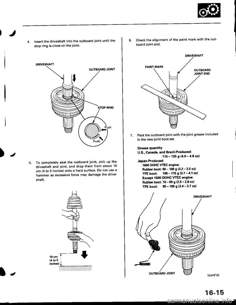
4. lnsert the driveshaft into the outboard joint until the
stop ring is close on the ioint.
DRIVESHAFT
To completely seat the outboard joint, pick up the
driveshaft and joint, and drop them from about 10
cm (4 to 5 inches) onto a hard surface. Do not use a
hammer as excessive force may damage the drive-
shaft.
16-15
J
6. Check the alignment of the paint mark with the out-
board joint end.
Pack the outboard joint with the joint grease includsd
in th€ new ioint boot set.
Gleaso quanlity
U.S., canada, and Brazil'Ploducod:
115 - 135 g {4.0 - 4.8 oz}
Japan-Producod:
161X, DOHC VTEC angino:
Rubbor boot: 90 - 100 g 13.2 - 3.5 oz)
TPE boot: 1tl6 - 115 I {3'7 - tl'l oz}
Excapt 1000 DOHC VTEC engine:
Rubbel boot: 70 - 80 g l.2.5 - 2.8 ozl
TPE boot: 95 - 105 g {3.4- 3.7 oz}
7.
DRIVESHAFT
(cont'd)
Page 1049 of 2189
Driveshafts
Reassembly lcont'd)
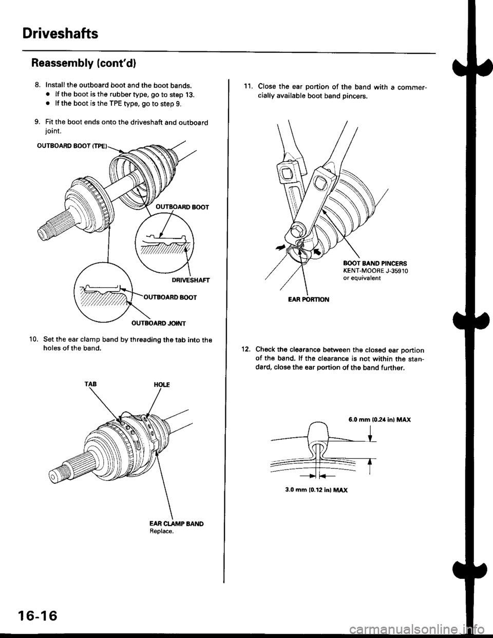
Installthe outboard boot and the boot bands.. lf the boot is the rubber type. go to step 13.. lf the boot is the TPE type, go to step 9.
Fit the boot ends onto the driveshaft and outboard
ioint.
10, Set the ear clamp band by threading the tab into theholes of the band.
EAR CLAMP BANDReolace.
8.
16-16
11. Close the ear portion of the band with a commer-cially available boot band Dincerc.
BOOT BAND PINCERSKENT-MOORE J,35910or eouivalent
Chsck the clearanca between the closed ear oonionof the band. lf the clesrance is not within the stan-
dard, close the ear portion of ths band further.
6.0 mm (0.24 in) MAX
3.0 mm 10.t2 inl MAX
EAR FOFNON
Page 1050 of 2189
I
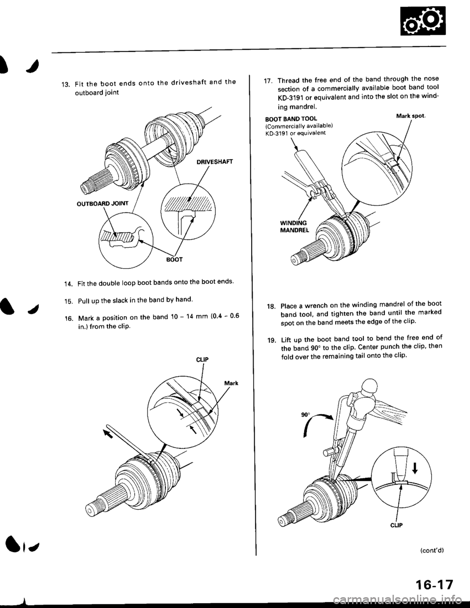
13. Fit the boot ends onto the driveshaft and the
outboard joint
Fit the double loop boot bands onto the boot ends'
Pull up the slack in the band by hand'
Mark a position on the band 10 - 14 mm {0 4 - 0 6
in,) from the cliP.
14.
16.
CLIP
lrz
17. Thread the free end of the band through the nose
section of a commercially avaiiable boot band tool
KD-3191 or equivalent and into the slot on the wind-
ing mandrel.
BOOT BAND TOOL
lCommerciallY available)
KD-3191 or equivalent
MANDREL
Place a wrench on the winding mandrel of the boot
band tool, and tighten the band until the marked
spot on the band meets the edge of the clip'
Lift uo the boot band tool to bend the free end of
the band 90" to the clip Center punch the clip, then
fold over the remaining tail onto the clip
Mark spot.
18.
1q
(cont'd)
16-17
Page 1051 of 2189
Driveshafts
Reassembly (cont'dl
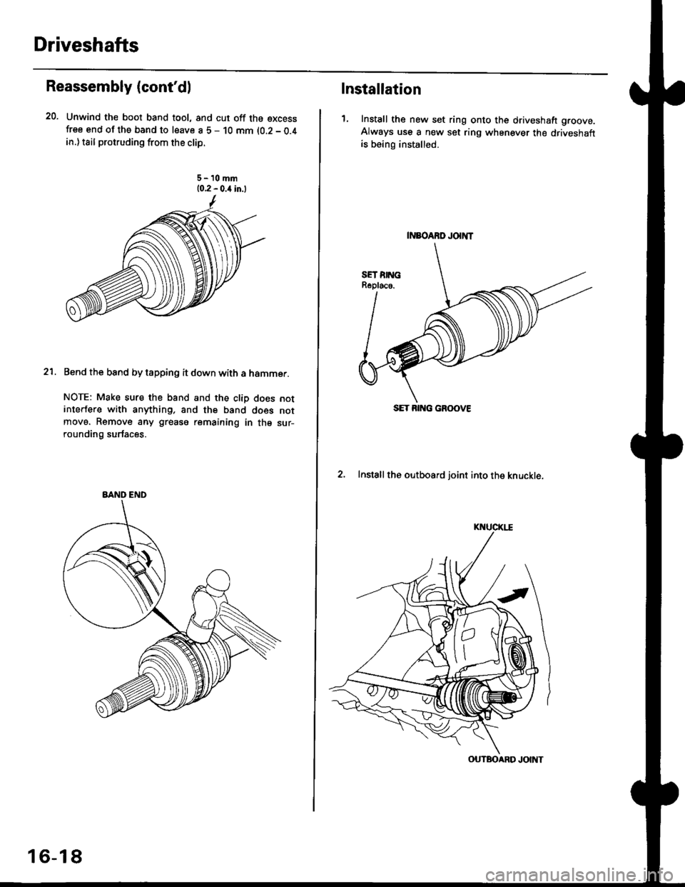
20. Unwind the boot band tool, and cut off the excessfree end of the band to leave a 5 - 10 mm (0.2 - 0.4in.) tail protruding from the clip.
21. Bend the band by tapping it down with a hammer.
NOTE: Maks sure the band and the clip does notinterfere with anything, and the band does notmov6. Remove any grease remaining in the sur-
rounding surtaces.
AANO END
16-18
INBOARD JOiIT
SET RII{G GR(X)VE
Installation
1, Install the new set ring onto the driveshaft groove.
Always use a new set ring whenever the driveshaftis being installed.
2. Install the outboard joint into the knuckte.
OUTBOARD JOINT
KNUCKI.E
Page 1052 of 2189
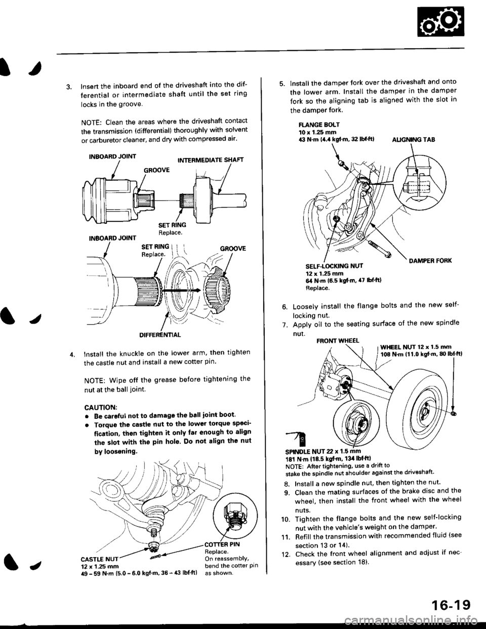
3. lnsert the inboard end of the driveshaft into the dif-
terential or intermediate shaft until the set ring
locks in the groove
NOTE: Clean the areas where the driveshaft contact
the transmission (differential) thoroughly with solvent
or carburetor cleaner, and dry with compressed air'
INBOARD JOINT
INBOARD JOINTReplace.
GROOVE
an
DIFFERENTIAL
lnstall the knuckie on the lower arm. then trghten
the castle nut and install a new cotter pin
NOTE: wipe off the grease before tightening the
nut at the ball ioint.
CAUTION:
. Be careful not to damago the ball ioint boot'
. Torque the castle nut to the lower torque sp€ci-
fication, thsn tighten it only far enough to align
the slot with th€ pin hol6. Do not align the nut
by loosening.
CASTLE NUT12 x 1 .25 mm
COTTER PINReplace.On reassemblY,bend the cotter pinJi$ - 59 N.m 15.0 - 6.0 kgl m,35 - 43 lbf ftl
16-19
5. lnstall the damper tork over the driveshaft and onto
the lower arm. Install the damper in the damper
fork so the aligning tab is aligned with the slot in
the damPer fork.
FLANGE BOLTl0 r 1.25 mmrit N.m t4.a kgf.m, 32 lbf.ft) AIIGN|NG TAB
1.
SELF-LOGKING NUT12 x 1.25 mm6,1N.m 16.5 kgi.m, a7 lbfftl
Replace.
Loosely install the flange bolts and the new self-
locking nut.
Apply oil to the seating surface of the new spindle
nut.
181 N m 118.5 kgt'm, 13il lbt'ftl
NOTE: Aftortightening, use a drift to
stake the spindle nut shoulder against the drivoshaft'
8. Install a new spindle nut, then tighten the nut'
9. Clean the mating surfaces ot the brake disc and the
wheel. then install the front wheel with the wheel
nuts.
10. Tighten the flange bolts and the new self-locking
nut with the vehicle's weight on the damper.
11. Refill the transmission with recommended fluid (see
section 13 or 14).'t2. Check the front wheel alignment and adjust if nec-
essary (see section 18),
FRONT WHEEL
SPINDLE NUT 22 x 1.5 mm
WHEEL NUT 12 x 1.5 mm108 N.m (11.0 kgl'm, g) lbl ftl
Page 1057 of 2189
l.
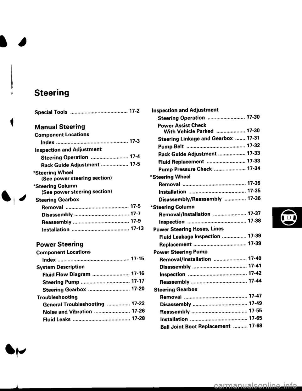
t
Steering
Speciaf Tools ....."'.....17-2
Manual Steering
Component Locations
lndex ................ ....... 17-3
Inspection and Adiustment
Steering Operation "'......"............... 17-4
Rack Guide Adiustment ................... 17-5
*Steering Wheel
(See power steering section)
*Steering Column
(See power steering sectionl
Steering Gearbox
Removal ................. 17-5
Disassembly ......."" 17-7
ReassemblY ..'......... 17-9
lnstallation ............. 17-13
Power Steering
Component Locations
lndex "......."..... """' 17-15
System DescriPtion
Fluid Flow Diagram .........""............. 17'16
Steering Pump ............'... "........"'...-- 17 -17
Steering Gearbox .".................'...'.'.' 17-20
Troubleshooting
Generaf Troubleshooting ..........--.... 17'22
Noise and Vibration ......................... 17 -26
Ffuid Leaks .............17-28
Inspection and Adiustment
Steering Operation'......."'........'...... 1 7-30
Power Assist Check
With Vehicle Parked .."................ 17-30
Steering Linkage and Gearbox ....." 17-31
Pump Beft ...--.""".. 17-32
Rack Guide Adiustment .'.......'.......'. 17'33
Fluid Replacement .....'.."................. 17-33
Pump Pressure Check .............'....-. " 17 -34
'Steering Wheel
Removal .."'........'... 17-35
lnstallation ............. 17-35
Disassembly/Reassembly ......'.....'.' 17-36
*Steering Column
Removal/lnstallation ....'........... ---.... 17'37
lnspection .............. 17'38
Power Steering Hoses, Lines
Fluid Leakage Inspeetion ............'.... 17-39
Replacement ......".. 17-39
Power Steering PumP
Removal/lnstallation .'.'..'..'............. 17-40
Disassembly ".........17-41
fnspection .......---'." 17'42
Reassembly ..'.........17-44
Steering Gearbox
Removal ....'........."' 17'47
DisassemblY ..........' 17-49
Reassembly '........... 17-55
lnstallation ............. 17-65
Ball Joint Boot Replacement .......'.. 17-68
Ir/
lp
Page 1058 of 2189
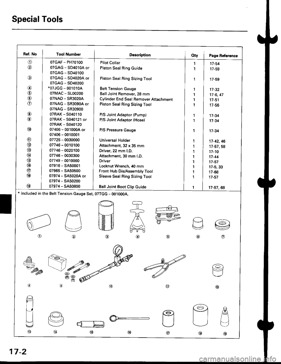
Ref. No I Tool NumberDescriptionOty I Pag€ Reterence
o
@
@
@
@
fof
@
@
@
@
@
@
@
@
@
@
@
@
@
07GAF - PH70100
07GAG - SD4010A or
07GAG - SD40100
07GAG - SD4020A or
07GAG - S040200*07JGG - 00r 010A
07MAC - 5100200
OTNAD - SR3O2OA
07NAG - SR3090A or
07NAG - SR30900
07RAK - 5040110
07RAK - 5040121 or
07RAK - 5040t20
07406 - 0010004 or
07406 - 001000r
07725 - 0030000
07746 - 0010100
07746 - 0020100
07746 - 0030300
07749 - 0010000
07916 - SA50001
07965 - SA50500
07974 - SA5020A or
07974 - SA50200
07974 - SA50800
Pilot Collar
Piston Seal Ring Guide
Piston Seal Ring Sizing Tool
Belt Tension Gauge
Ball Joint Remover, 28 mm
Cylinder End Seal Bemover Attachment
Piston Seal Ring Sizing Tool
P/S Joint Adaptor (Pump)
P/S Joint Adaptor (Hose)
P/S Pressure Gauge
Universal Holder
Attachment,32 x 35 mm
Driver, 22 mm l.D.
Attachment, 30 mm l.D.
Driver
Locknut Wrench, 40 mm
Front Hub DiVAssembly Tool
Sleeve Seal Ring Sizing Tool
Bsll Joint Boot Clip Guide
1
1
'I
1'I
1
I
1
1
I
1
1
I
1
1
I
1
I
11-54
17-59
'17-59
17 -32
17 -6, 47
17-51
| /-ao
17 -34
17 -31
't7 -34
't7-42, 16
17-57,58
17-10
17-44't7 -57
17-5,33
17-68
17 -57
17-57, 6A* lncluded in the Belt Tension cauge Set, 07TGG - OO10OOA.
o
p
v
@o
€_
ts7-dysB
aal
@@
(o)
F=1
@@@
@@@
17-2