dashboard wire harness HONDA CIVIC 1999 6.G Owner's Manual
[x] Cancel search | Manufacturer: HONDA, Model Year: 1999, Model line: CIVIC, Model: HONDA CIVIC 1999 6.GPages: 2189, PDF Size: 69.39 MB
Page 1714 of 2189
Cruise Gontrol
3.
1.
2.
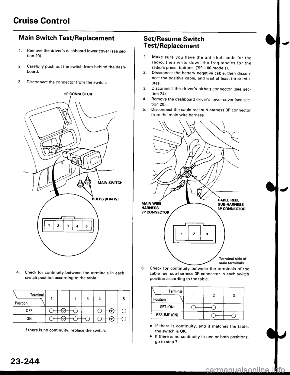
Main Switch Test/Replacement
Remove the driver's dashboard lower cover (see sec-tion 20).
Carefully push out the switch from behind the dashboard.
Disconnect the connector from the swtrcn.
MAIN SWITCH
BULBS {0.84 Wt
Check for continuity between the terminals in eachswitch position according to the table.
lf there is no continuity. reDlace the switch.
4.
Terminal
r**
--\235
OFFo--oGa\-o\:./\a/
ONo-/a-oo--o\:/\:/
23-244
Set/Resume Switch
5.
Test/Replacement
2.
1.
MAIN WIREHARNESS3P CONNECTOR
Make sure you have the anti-theft code for theradio, then write down the frequencies for theradio's preset buttons. ('99 - 00 models).Disconnect the battery negative cable, then discon-nect the positive cable, and wait at least three min-utes.
Disconnect the driver's airbag connector (see sec-tion 24).
Remove the dashboard driver's lower cover (see sec,tion 20).
Disconnect the cable reel sub harness 3p connectorfrom the main wire harness.
CABLE BEELSUB-HARNESS3P CONNECTOS
Terminalside ofmale terminals
Check for continuity between the terminals of thecable reel sub-harness 3P connector in each switchposition according to the table.
L Terminal
Position123
SET (ON}o----o
BESUi,|E IONIo-----o
lf there is continuity, and it matches the table,the switch is OK.
lf there is no continuity in one or both positions,
go to step 7.
Page 1741 of 2189
Component/Wiring Locations
)
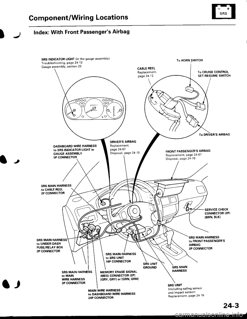
Index: With Front Passenger's Airbag
SRS INDICATOR LIGHT (ln the gauge assemblvl
Troubleshooting, Page 24 13
Gauge assembly, section 23CABLE REEL
Replacemenlpage 2!-t 2
To HORN SWITCH
SRS UNIT(lncluding safing sensor
and imPact sensorl
Replacement Page 24 76
To DRIVER'S AIRBAG
DASHBOARD WIRE HARNESS
to SRS INDICATOB LIGHT in
GAUGE ASSEMBLY5P CONNECTOB
DBIVER'S AIRBAG
Beplacement,page 24-61Disposal, page 24 70FRONT PASSENGER'S AIBBAG
Replacement, Page 24_67
Disposal, Page 24 70
t
SRS MAIN HARNESSto CABI-E RE€L2P CONNECTOR
SRS MAIN
SERVICE CHECKCONNECTOR {2PI
IBRN, BLK]
to UNOER-OASHFUSE/RELAY BOX2P CONNECTOR
SRS MAIN HARNESSto FRONT PASSENGER'SAIRBAG2P CONNECTOB
SRS MAIN HARNESSto SRS UNITr8P CONNECTOR
SBS MAIN HARNESSto MAINWIRE HARNESS3P CONNECTOR
MEMORY ERASE SIGNAL(MES) CONNECTOR I2P)
[GRY, GRYI or IGRN. GRNI
MAIN WIRE HARNESSto DASHBOARD WIRE HARNESS
24P CONNECTOR
2+3
t,
Page 1742 of 2189
Gomponent/Wiring Locations
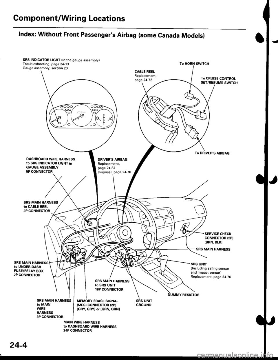
Index: Without Front Passenger's Airbag (some Canada Modelsl
SRS INDICATOR LIGHT (ln the gauge assembly)Troubleshooting, page 24-13Gauge assembly, section 23
DRIVER'S AIRSAGReplacement,page 24-67Disposal, page 24-70
SRS UNITGROUNO
To HORN SWITCH
SRS MAIN HARNESS
SRS UNIT{lncluding safing sensorand impact sensor)Replacement. page 24,76
To CRUISE CONTROLSET/RESUME SWITCH
oo/ \oo
To DRIVER,S AIRBAG
DASHBOARD WIRE HARNESSto SRS INDICATOR LIGHT inGAUGE ASSEMBLY5P CONNECTOR
SERVICE CHECKCONNECTOR {2P}IB8N, BLKI
SRS MAINto UNDER-DASHFUSE/RELAY BOX2P CONNECTOR
SRS MAIN HARNESSto SRS UNIT18P CONNECTOR
SRS MAIN HARNESSto MAINWIREHARNESS3P CONNECTOR
MEMORY ERASE SIGNAL(MES) CONNECTON (2P'
IGRY, GRYI o. IGRN, GRNI
MAIN WIRE HARNESSto DASHBOARD WIRE HARNESS24P CONNECTOR
24-4
DUMMY RESISTOB
Page 1746 of 2189
Precautions/Procedu res
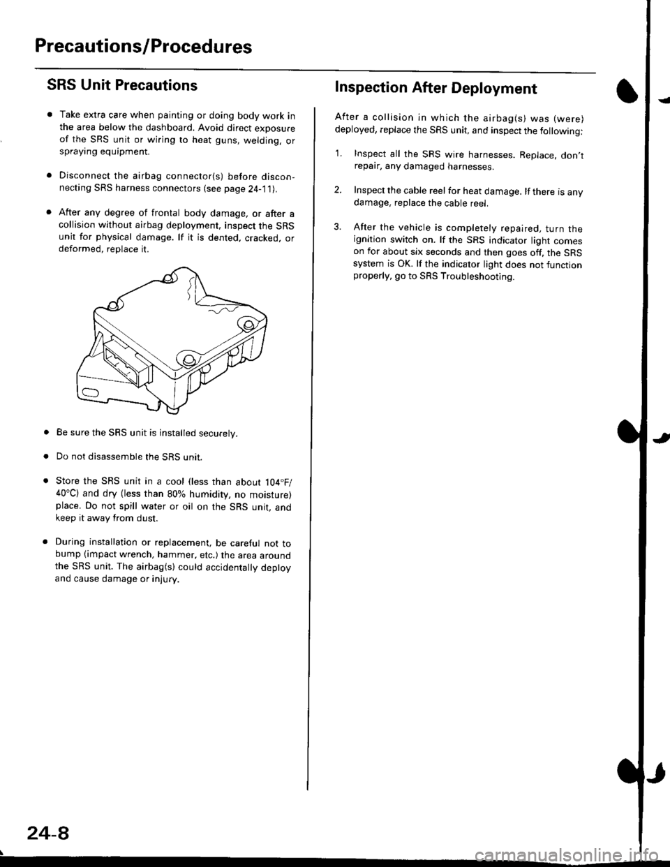
SRS Unit Precautions
Take extra care when painting or doing body work inthe area below the dashboard. Avoid direct exDosureof the SRS unit or wiring to heat guns, welding. orsprayang equipment.
Disconnect the airbag connector(s) before discon-necting SRS harness connectors (see page24-1|1J.
After any degree of frontal body damage, or after acollision without airbag deployment, inspect the SRSunit for physical damage. lf it is dented. cracked, ordeformed, replace it.
Be sure the SRS unit is installed securely.
Do not disassemble the SRS unit.
Store the SRS unit in a cool (less than about 104.F/40"C) and dry (less than 80% humidity, no moisture)place. Do not spill water or oil on the SRS unit, andkeep it away from dust.
During installation or replacement, be careful not tobump (impact wrench, hammer, etc.) the area aroundthe SRS unit. The airbag(s) could accidentally deptoyand cause damage or injury.
24-8
Inspection After Deployment
After a collision ln which the airbag(s) was (were)
deployed, replace the SRS unit, and inspect the following:
1. Inspect all the SRS wire harnesses. Replace. don,trepair, any damaged harnesses.
2. Inspect the cable reel for heat damage. lf there is anydamage, replace the cable reel.
3. After the vehicle is completely repaired, turn theignition switch on. lf the SRS indicator light comeson for about six seconds and then goes off. the SRSsystem is OK. lf the indicator light does not functionproperly, go to SRS Troubleshooting.
Page 1763 of 2189
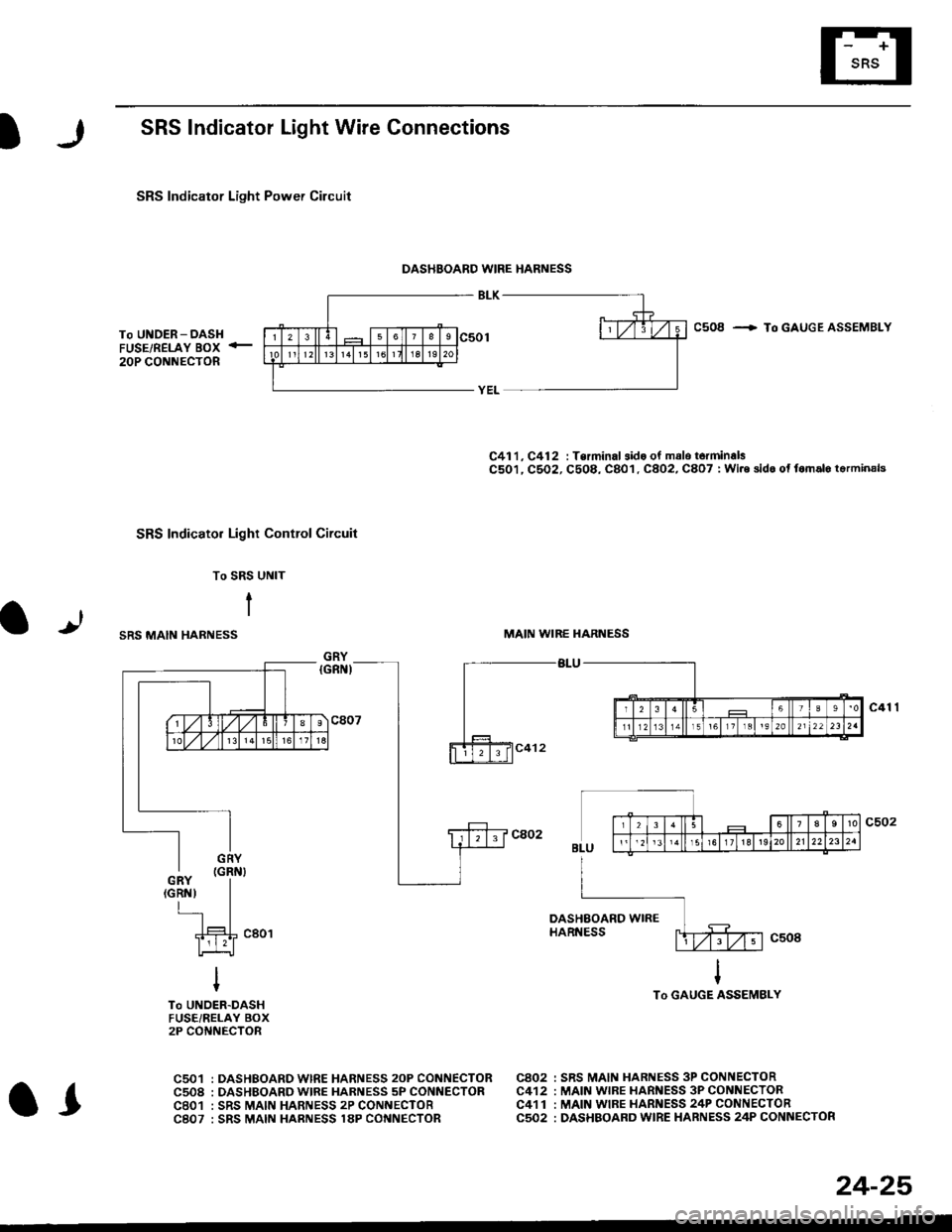
SRS Indicator Light Wire Connections
SRS Indicator Light Power Circuit
DASHBOARD WIRE HARNESS
To UNDER-DASHFUSE/RELAY BOX -
20P CONNECTOR
SRS Indicato. Light Control Circuit
To SRS UNIT
tI
SRS MAIN HARNESS
C41 1, C412 : Terminal sido of mdlo t6rminalsC501, C5O2, C508, C801. C802, C807 : Wi.6 sidc of fomalo t.rminals
MAIN WIBE HARNESS
BLU
C508 -+ To GAUGE ASSEMBLY
c41 1
To GAUGE ASSEMBLY
at
C501 : DASHBOARDWIRE HARNESS 2oP CONNECTORC508 : DASHBOARD wlRE HARNESS 5P CONNECTORC801 : SRS MAIN HARNESS 2P CONNECTORC807 : SRS MAIN HARNESS 18P CONNECTOR
C802 : SRS MAIN HARNESS 3P CONNECTORC412 : MAIN WIRE HARNESS 3P CONNECTORC41 1 : MAIN WIRE HARNESS 24P CONNECTORC502 : DASHBOARD WIRE HARNESS 24P CONNECTOR
GRY
OI
24-25
Page 1765 of 2189
)
From page 24-26
(A)
From page 24-26
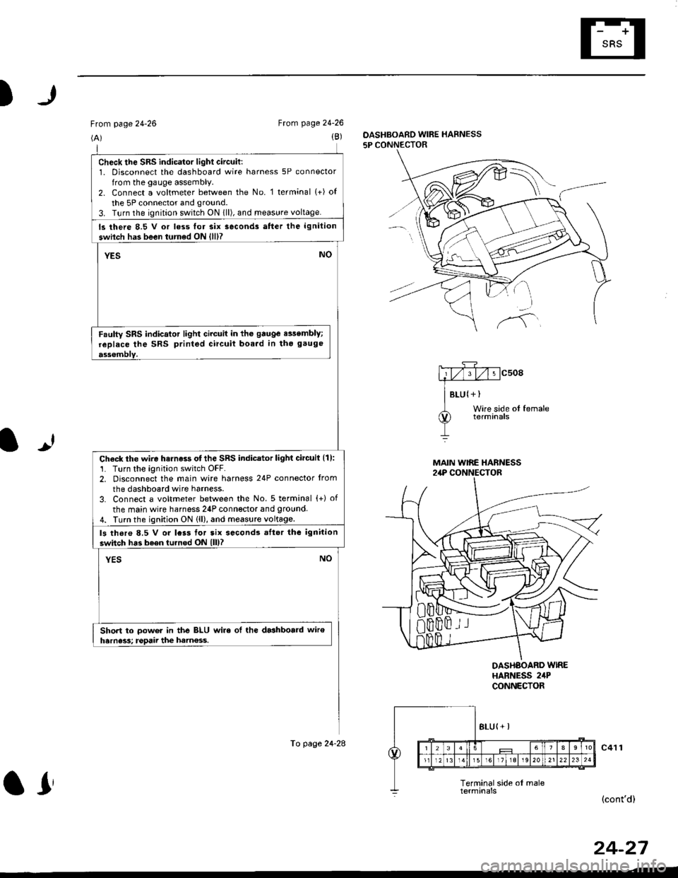
(B)DASHBOARD WIRE HARNESS
5P CONNECTOR
It
MAIN WIRE HARNESS2,rP CONNECTOR
DASHAOARD WIREHARNESS 2irPCONNECTOR
c41 1
(cont'd)
24-27
check the sRs indicator light circuit:1. Disconnect the dashboard wire harness 5P connector
from the gauge assembly.2. Connect a voltmeter between the No. 1 terminal (+) of
the 5P connector and ground.
3. T!rn the ignition switch ON 1ll), and meas!re voltage.
ls there 8.5 V or loss lor six seconds atter the ignition
swilch has been turned ON {lll?
YESNO
Faulty SRS indicator light circuit in the gauge e$embly;
replace the SRS printed circuit boa.d in tho gauge
ass€mblY.
Check the wire harness otthe SRS indicator light circuil {1):'1. Turn the ignition switch OFF.2. Disconnect the main wire harness 24P connector from
the dashboard wire harness.
3. Connect a voltmeter between the No. 5 terminal {+) of
the main wire harness 24P connector and 9round4. Turn the ignition ON (ll), and measure voltage.
ls thore 8.5 V or lcss tor tix second3 .Itor the ignition
switch has b6en turned ON lll)?
YESNO
Short to oower in the BLU wire ol the dashboald wiroharness; rgpaii the ham€ss.
To page 24-28
ar
Page 1769 of 2189
)
From page 24'30(B)
To page 24-33
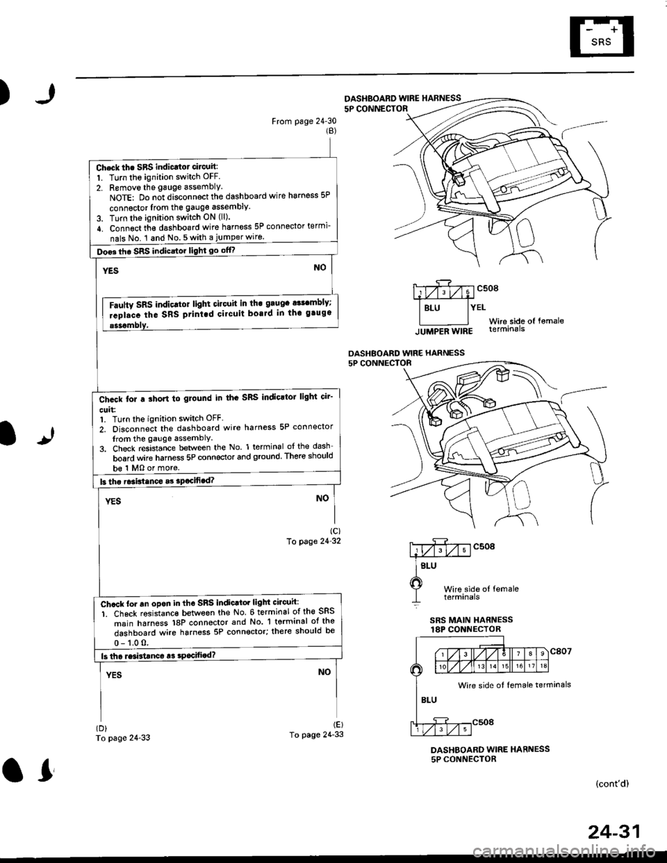
5P CONNECTOF
mcsogA#
I Btu lYEtWire side of fomale
lUUpeA Wtng terminals
OASHBOARD WIRE HARNESS
It
Wire side ol femaletetmtnals
SRS MAIN HARNESSlAP CONNECTOR
(D)
To page 24'33
DASHBOARD WIRE HARNESS5P CONNECTOR
(cont'd)
DASHBOARD WINE HARNESS
Check th. SBS indicatot circuit:
1. Turn the ignition switch OFF.
2. Removo the gauge assembly.
NoTE: Do n;t disconnect the dashboard wire harness 5P
connsctor lrom the gauge assembly
3. Turn the ignition switch ON (ll).
4. Connect th€ dashboard wire harness 5P connector termi-
nals No. 1 and No.5with a jumperwiro.
Doo3th. SRS indicstor light go offf
Fautty SRS indicltot light citouit in th. grugc a$cmbly;
rcpl.ce the SRS ptint.d cilcuit boaJd in thc gtugs
b€ 1 MO or more.
Ch.ck tor a ihort to glound in th. SRS IndioltoJ light cir'
cuit:1. Turn the ignition switch OFF.
2. Disconnect the dashboard wire harness 5P connector
from the gauge assemblY
3. Check resistance between the No. 1 terminal of the dash
board wire harness 5P connector and ground. There should
Ch.ck to. an opon in tho SnS indic.tor light circuh:
1. Ch6ck resistanc€ between the No 6 terminal of the SRS
msin harness 18P connector and No. 'l terminal ot the
dashboard wire harness 5P connector; there should be
Wire side ot female terminals
24-31
or
Page 1770 of 2189
Troubleshooting
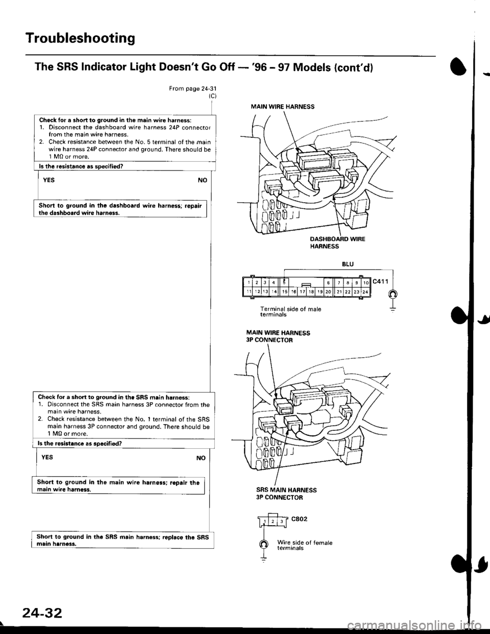
The SRS Indicator Light Doesn't Go Off -'96 - 97 Models (cont'dl
From page 24-31
Ch6ck for a shon lo ground in tho m.in wire harness:1. Disconnect the dashboard wire harness 24P connectorfrom the main wire harness,2. Check resistance between the No. 5 terminal of the mainwire harness 24P connector and ground. There should be1 M0 or more.
Short to ground in the dashboard wire harness; repairthe dashbo..d wire harnoss.
SRS MAIN HARNESS3P CONNECTOR
Wire side oI femaleterminals
24-32
\
MAIN WIRE HARNESS
HARNESS
Check for a short to ground in the SRS main h..ness:1. Disconnect the SRS main harness 3P connector from themain wire harness,2. Check resistance between the No. 1 terminal of the SRSmain harness 3P connector and ground. There shorrld be1 fu,|0 or more.
ls the resistance as specifisd?
Short to ground in the main wire harnoas; r€pair themain wire harness.
Page 1771 of 2189
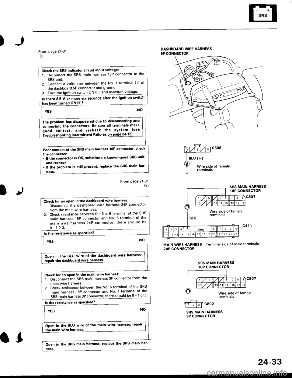
)
From page 24-31(Dl
DASHBOARD WIBE HARNESS
5P CONNECTOR
Wire side of temaletermtnars
From page 24-31(El
lr
SRS MAIN HARNESS18P CONNECTOR
Check for an open in the dashboatd wir€ harness:
1. Disconnect the dashboard wire harness 24P connector
from the main wire harness.
2. Check resistance between the No. 6 terminal of the SRS
main harness 18P connector and No 5 terminal of the
main wire harness 24P connector; there should be
0- 1.0 0.
Ooen in tha BLU wire ot the dashboard wire harness;
the dashboard wiie harness.
MAIN WIRE HARNESS Terminal side ot male termlnals
24P CONNECTOR
SRS MAII{ HARI{ESSlaP CONI{ECTOR
SRS MAIN HARNESS3P CONNECTOR
Check lho SRS indicator Gircuit input voliage:
1. Reconnect the SRS main harness 18P connector lo the
SRS unit.2. Connect a voltmeter between the No. 1 terminal (+) of
the dashboard 5P connector and ground
3. Turn the ignition switch ON (ll), and measure
ls there 8.5 V or more six seconds after lhe ignilion switch
has been turned ON (lll?
The Droblem h.s disappe.red due to disconnecting antl
connecting the connectors. Be sure all lerminals mako
oood contact, and recheck the syslem lsoe
iroubleshooting Intermittent Failure3 on page 2{-151'
Poor contact at the SRS main h.rn6s 18P connector; ch'ck
lI the problem k still present, replace the SRS main har'
Check for an open in the main wire harness:
1. Disconnect the SRS main harness 3P connector from the
main wire harness.
2. Check resistance between the No 6 terminal of the SRS
main harness 18P connector and No 1 terminal of the
SRS main harness 3P connector; there should be 0 - 1 0 o
ls the resistance as sp€cilied?
ODen in the BLU wire of the main wire hamess; tepair
the main wire harness.
Ooen in the SRS main harness; replace lhe SRS main har
24-33
.L
Page 1773 of 2189
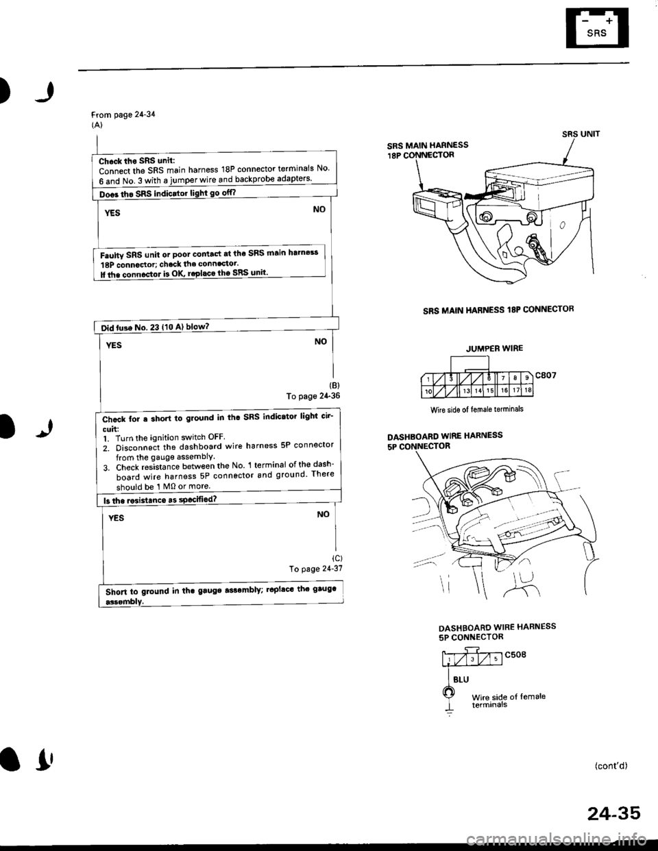
)
From page 24-34(A)
SRS MAIN HARNESS I8P CONNECTOR
(B)
To page 24-36
1)
Wire sidg of lemale terminals
DASHBOARD WIRE HARNESS
5P CONNECTOR
ic)To page 21'31
DASHBOARD WIRE HARNESS
5P CONNECTOR
c508
t of lemale
(cont'd)
24-35
SRS MAIN HARNESS
Chock iho SRS unit:
Connect the SRS main harness 18P connector terminals No'
6 and No. 3 with a jumper wire and backprobe
Doos tho SRS indicator light go off?
Faulw SRS unit or poot co tact at the SRS ftain htmes!
18P connoctor; chack the connagtot.
ll tha connoctor b OK roplaca lho SRS unit'
oid tu3e No. 23 t10 A) blow?
Chcck for e short to ground in th. SRS indicator lighi cir-
cuh:1. Turn the ignition switch OFF
2. Disconneit the dashboard wire harness 5P connector
from the gauge assembly.
3. Check res-ista;ce between the No l terminai ofth€dash-
board wire harness 5P connector and ground There
should be '1 M0 or more.
Short to glound in th. gaugs aslomblY; .6plac' th' gtug'
JUMPEB WIRE
o!