ac line HONDA CIVIC 1999 6.G Workshop Manual
[x] Cancel search | Manufacturer: HONDA, Model Year: 1999, Model line: CIVIC, Model: HONDA CIVIC 1999 6.GPages: 2189, PDF Size: 69.39 MB
Page 1025 of 2189
l.
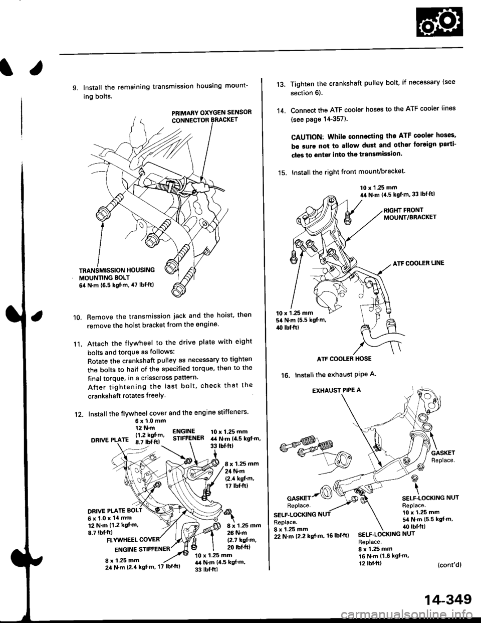
9. Install the remaining transmission housing mount-
ing bolts.
PRIMARY OXYGEN SENSOR
Remove the transmission jack and the hoist. then
remove the hoist bracket from the engine'
Attach the flvwheel to the drive plate with eight
bolts and torque as follows:
Rotate the crankshaft pulley as necessary to tighten
rhe bolts to half of the specified torque, then to the
final torque, in a crisscross pattern.
After tightening the last bolt. check that the
crankshaft rotates freelY.
10.
11.
12. Install the flywheel cover and the engine stiffeners
DRIVE
6xl.0mm12 N.m
- l12 kgf'm'rE 8.7 tbf.ftl
ENGINESTIFfENEB10 x 1.25 mmart N.m la.s kgt.m,33 tbtftt
8 x 1.25 mm24 N.m(2.1 kgf'm,17 tbt.ftt
DRIVE PI.ATE BOLT
6x1.0x14mm12 N.m {1.2 kgt m.
8.7 lbf,ftl8 x 1.25 mm26 N.m
12.7 kqfin,20 rbt'ftlFLYUTHEEL
ENGINE STIFFENER
8 x 1.25 mm10 x 1.25 mmr,a N.m {4,5 kgf m,
33 tbf.ftl
TRANSMISSION HOUSING
MOUNNNG BOLT
6il N.m {6.5 kgf.m, 47 lbf'ftl
24 N.m (2.4 kgt'm, '17 lbf'ftl
22 N.m t2.2 kgl m, 16lbf'ftl
14-349
13.
14.
Tighten the crankshaft pulley bolt, if necessary (see
section 6).
Connect the ATF cooler hoses to the ATF cooler lines
(see page 14-357).
CAUTION: Whilo connecting the ATF cooltr hGes,
b€ sure not lo allow dust and other loreign parti-
cles to entg. into the transmission.
15. Installthe right front mounvbracket'
10 x 1.25 mm
a,r N.m {4.5 kgf'm,33 lbt ftl
RIGHT FRONTMOUNT/BRACKET
ATF COOLER LINE
10 x 1 .25 mm54 N.m {5.5 kgt'm,
4{) tbl.ftt
ATF COOI,TR HOSE
16. Installthe exhaust PiPe A.
EXHAUST PIPE A
GASKETReplace.
@
\SELF.LOCKING NUTReplace.10 x 1.25 mm5/a N.m {5.5 kgt m,irc lbf.ft)
(cont'dl
*s$o
oor*rr-@Replace.
SELF.LOCKINGReplace.8 x 1.25 mmSELF.LOCKING NUT
Replace.8 x 1.25 mm16 N.m {1.6 kgl'm,12 tbl.ftt
Page 1028 of 2189
Transmission
Gooler Flushing
@ To prevent iniury to face and eyes, alwayswear safety glasses or a tace shield when using thetransmission flusher.
NOTE: This procedure should be performed before rein-stalling the transmission.
'1. Check the tools and hoses for wear and cracks before
using. lf wear or cracks are found, reDlace the hoses
before using.
4.
Using the measuring cup. fill the tank with 2,1 ounces(approximately 2/3 full) of biodegradable flushingfluid (J35944 - 20). Do not substitute with any otherfluid. Follow the handling procedure on the fluidcontatner.
Secure the flusher filler cap, and pressurize the tankwith compressed air to between 5S0 - 829 kpa (5.6 -
8.45 kgf/cm'�, 80 - 120 psi).
NOTE: The air line should be equipped with a watertrap to ensure a dry air system,
Hang the tool under the vehicle.
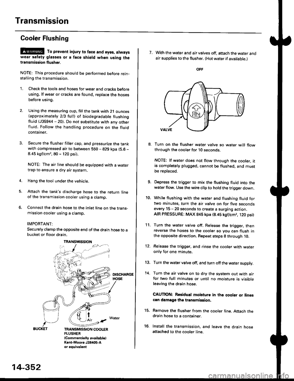
Attach the tank's discharge hose to the return lineoi the transmission cooler using a clamp.
Connect the drain hose to the inlet line on the trans-mission cooler using a clamp.
IMPORTANT:
Securely clamp the opposite end ofthe drain hose to abucket or floor drain,
t
TRANSMISSION COOLERFLUSHER{Commercially available)Kent-Moore J384O5-Aor oouivalent
TRANSMISSION
14-352
7. With the water and air valves off, attach the water andair supplies to the flusher. (Hot water if available.)
8. Turn on the flusher water valve so water will flowthrough the cooler for 10 seconds.
NOTE: lf water does not flow through the cooler, itis completely plugged, cannot be flushed, and mustbe replsced.
9. Depress the trigger to mix the flushing fluid into thewater flow. Use the wire clip to hold the trigger down.
'10. While flushing with the water and flushing fluid fortwo minutes. turn the air valve on for five secondsevery 15 - 20 seconds to create a surging action.AIR PRESSURE: MAX 845 kpa (8.45 kgflcmr, 120 psi)
11. Turn the water valve off. Release the trigger, thenreverse the hoses to the cooler so you can flush inthe opposite direction. Repeat steps 8 through 10.
12. Release the trigger. and rinse the cooler with wateronly for one minute.
13, Turn the water valve off, and turn off the water supply.
'14. Turn the air valve on to dry the system out with airfor two full minutes or until no moisture is visibleleaving the drain hose.
CAUTION: Rosidual mobturo in the qooler or linescln damage the transmission,
15. Remove the flusher from the cooler line. Attach thedrain hose to a container.
16. Install the transmission. and leave the drain hoseattached to the cooler line.
Page 1029 of 2189
![HONDA CIVIC 1999 6.G Workshop Manual l.
17.Make sure the transmission is in the E] position.
Fill the transmission with cvT Fluid, and run the
engine for 30 seconds or until approximately 0 95 {
(1.0 US qt.,0.8 lmp qt.) is discharged.
Re HONDA CIVIC 1999 6.G Workshop Manual l.
17.Make sure the transmission is in the E] position.
Fill the transmission with cvT Fluid, and run the
engine for 30 seconds or until approximately 0 95 {
(1.0 US qt.,0.8 lmp qt.) is discharged.
Re](/img/13/6068/w960_6068-1028.png)
l.
17.Make sure the transmission is in the E] position.
Fill the transmission with cvT Fluid, and run the
engine for 30 seconds or until approximately 0 95 {
(1.0 US qt.,0.8 lmp qt.) is discharged.
Remove the drain hose, and reconnect the cooler
return hose to the transmission (see page 14-355)
Refill the transmission with CVT Fluid to the proper
level (see page 14-299).
18.
'19.
.l ,
TOOL MAINTENANCE
1. Empty and rinse after each use. Fill the can with water
and pressurize the can. Flush the discharge line to
ensure that the unit is clean.
2, lf discharge liquid does not foam, the orifice may be
blocked.
3. To clean, disconnect the plumbing from the tank at
the large couPling nut.
FILTER
\
\- 0--D
i
I
O.RING
Remove the in-line tilter from the discharge side and
clean if necessary'
The fluid orifice is located behind the filter. Clean it
with the pick stored in the bottom of the tank han-
dle. or blow it clean with air. Securely reassemble
all parts.
COUPLINGNUT
II
-@q
\ORIFICE
FILLER CAP
14-353
Page 1033 of 2189
Shift Indicator PanelATF Gooler/Hoses
Adjustment
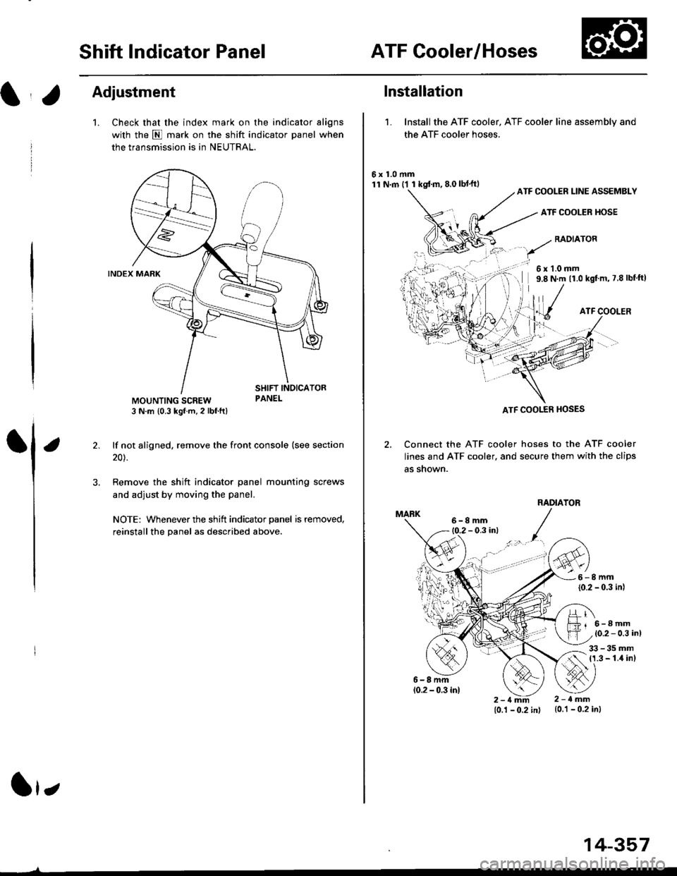
1.Check that the index mark on the indicator aligns
with the E mark on the shift indicator panel when
the transmission is in NEUTRAL.
lf not aligned, remove the front console {see section
20).
Remove the shift indicator panel mounting
and adjust by moving the panel.
NOTE: Whenever the shift indicator panel is removed,
reinstallthe Danel as described above.
It,
14-357
lnstallation
1. Installthe ATF cooler, ATF cooler line assembly and
the ATF cooler hoses.
6x1.0mm11 N.m ('l 1 kgf.m,8.0lbl'ftlATF COOLER LINE ASSEMBLY
ATF COOLER HOSE
RADIATOR
6x1.0mm9.8 N.m 11.0 kgf'm, 7 8 lbf'ft)
ATF COOLER
Connect the ATF cooler
lines and ATF cooler. and
as shown.
hoses to the ATF cooler
secure them with the clips
1l lTf{il.T
6-8mm10.2 - 0.3 in)
33-35mm11.3 - 1.4 inl
2-1mm10.1 - 0.2 in)
2-ilmm{0.1 - 0.2 in)
ATF COOI..ER HOSES
Page 1036 of 2189
Driveshafts
Inspection
Driveshaft Boot
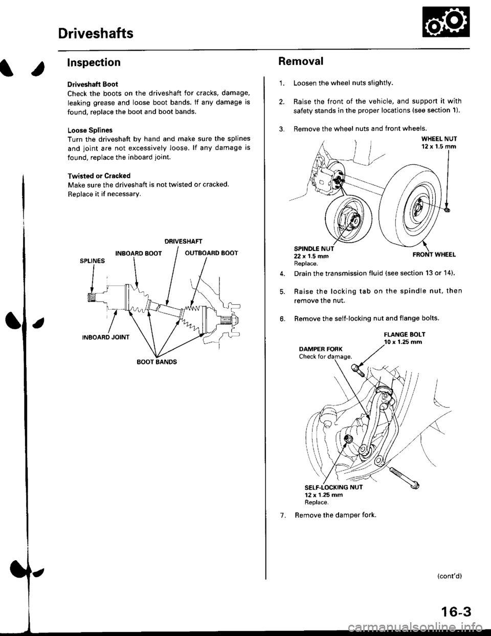
Check the boots on the driveshaft for cracks, damage,
leaking grease and loose boot bands. lf any damage is
found, replace the boot and boot bands,
Loose Splines
Turn the driveshaft by hand and make sure the splines
and joint are not excessively loose. lf any damage is
found, replace the inboard joint.
Twisied or Cracked
Make sure the driveshaft is not twisted or cracked.
Reolace it if necessarv.
DRIVESHAFT
BOOT BANDS
1.
Removal
Loosen the wheel nuts slightly.
Raise the front of the vehicle, and support it with
safety stands in the proper locations (see section 'l).
Remove the wheel nuts and front wheels.
Drain the transmission fluid (see section 13 or 14).
Raise the locking tab on the spindle nut, then
remove the nut.
Remove the selJ-locking nut and flange bolts.
FLANGE BOLT10 x 1.25 mm
(cont'd)
16-3
1.
Page 1038 of 2189
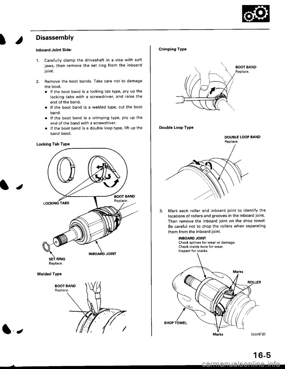
t
Disassembly
lnboard Joint Side:
1. Carefully clamp the driveshaft in a vise with soft
jaws, then remove the set ring from the inboard
joint.
2. Remove the boot bands. Take care not to damage
the boot.
. lf the boot band is a locking tab type, pry up the
locking tabs with a screwdriver, and raise the
end of the band.
. It the boot band is a welded type, cut the boot
ba nd.
. lf the boot band is a crimping type, pry up the
end of the band with a screwdraver.
. lf the boot band is a double loop type, lift up the
band bend.
Locking Tab Typs
Welded Type
J
Replace.
l,
Crimping Type
Double Loop Type
Mark each roller and inboard joint to identify the
locations of rollers and grooves in the inboard joint.
Then remove the inboard joint on the shop towel.
Be careful not to drop the rollers when separating
them from the inboard ioint.
INBOARD JOINTCheck splines for wear or damage,Check inside bore for wear.Inspect for cracks.
(cont'd)
16-5
Page 1039 of 2189
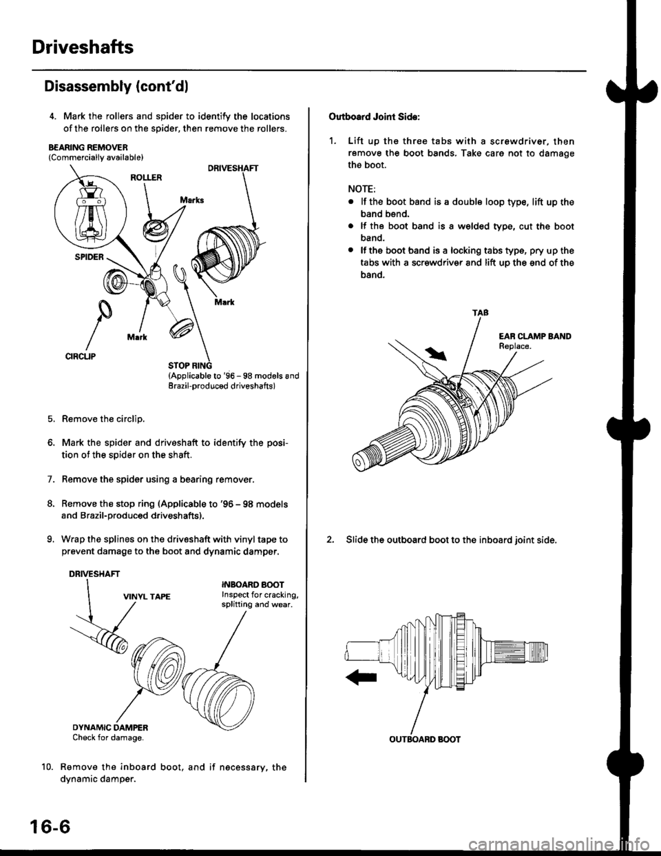
Driveshafts
Disassembly (cont'dl
4. Mark the rollers and spider to identify the locations
of the rollers on the sDider, then remove the rollers.
B€ARING REMOVER{Commerciallv available}
STOP RING(Applicable to '96 - 98 modols andErazil-produced driveshafts)
Remove the circlip.
Mark the spider and driveshaft to identify the posi-
tion ot the spider on the shaft.
Remove the spider using a bearing remover.
Remove the stop ring (Applicable to '96 - 98 models
and Brazil-produced driveshafts).
Wrap the splines on the drivsshaft with vinyl tape to
prevent damage to the boot and dynamic damper.
DRIVESHAFT
1.
VINYL TAPE
DYNAMIC DAMPERCheck for damage.
Remove the inboard
dynamic damper.
INBOARO AOOTInspect for cracking,splitting and wear.
16-6
boot, and if necessary, the
Outboard Joint Side:
1. Lift up thc three tabs with a screwdriver, then
remove the boot bands, Take care not to damage
the boot.
NOTE:
. lf the boot band is a double loop type, lift up the
band bend.
. lf the boot band is a welded type, cut the boot
band.
. lfthe boot band is a locking tabs type, pry up the
tabs with a scr€wdriv€r and lift uo the snd of the
band.
2. Slide the outboard boot to the inboard ioint side.
TAB
OUTBOABD BOOT
Page 1043 of 2189
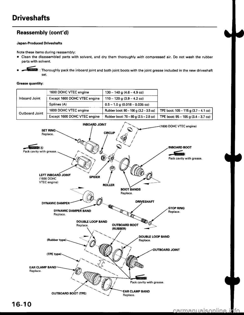
Driveshafts
Reassembly (cont'dl
Japan-Produced Driveshafts
Note these items during reassembly.
. Clean the disassembled pans with solvent, and dry them thoroughly with compressed air. Do not wash the rubber
parts with solvent.
o r@l : Thoroughly pack the inboard joint and both joint boots with the joint grease included in the new driveshaft
set.
Grease quantity:
Inboard Joint
1600 DOHC WEC engine130 - 140 9 (4.6 - 4.9 oz)
Except 1600 DOHC VTEC engine110 - 120 g (3.9 - 4.2 oz)
Splines (Al0.5 - 1.0 g (0.018 - 0.035 oz)
Outboard Joint
'1600 DOHC WEC engineRubber boot 90 - 'l 00 g (3.2 - 3.5 oz)TPE boot; 105 - 115 9 (3.7 - 4.1 oz)
Except 1600 DOHC VTEC engineRubber boot 70 - 80 g |'2.5 - 2.8 ozlTPE boot 95 - 105 g (3.4 - 3.7 oz)
{1600 DOHC VTEC angine)
SET RINGReplace.
-6{@INBOARD BOOT
-6;Pack cavity with grease.
Pack cavity with grease.
DYNAMIC DAMPER
DYNAMICReplace.
DOUA|.I Lq)P BANDReplace.
(Rubber typc)LOOP BANDReplace.
Pack cavity with grease-
CLAMP BAND
],*"u, ,"^S
/ t'.t$ ,''
,/s
-'-
OUTBOARD BOOTIRUEBER)
16-10
tttt t*' -----_.r...-
._
Replace.
Page 1044 of 2189
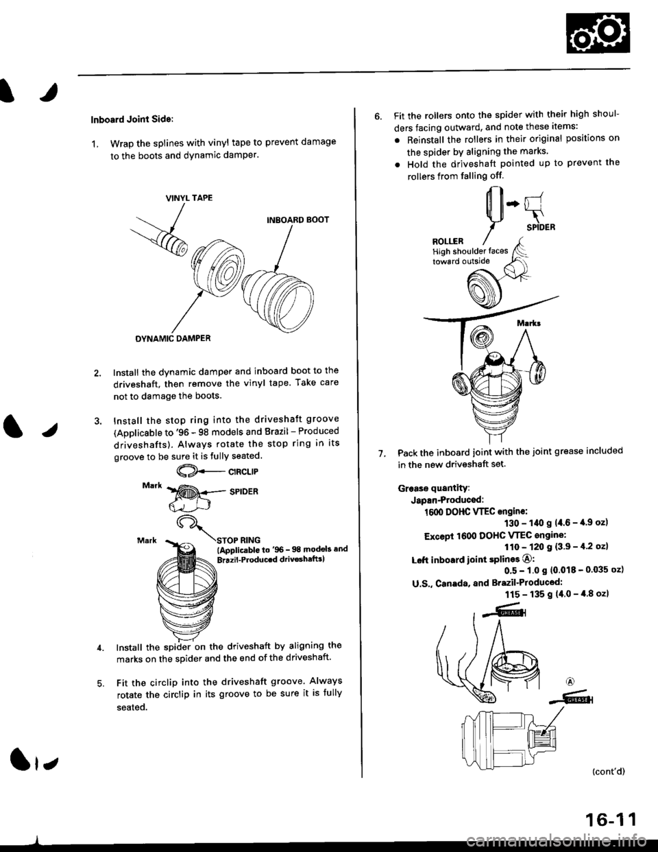
lnboard Joint Side:
1, Wrap the splines with vinyl tape to prevent damage
to the boots and dynamic damPer.
TAPE
INBOARD BOOT
DYNAMIC DAMPER
Install the dynamic damper and inboard boot to the
driveshaft, then remove the vinyl tape. Take care
not to damage the boots.
Install the stop ring into the driveshaft groove
(Applicsble to '96 - 98 models and Brazil - Produced
driveshafts). Always rotate the stop ring in its
groove to be sure it is fully seated.
@--c't"t't
STOP RING(ApplicablG to'96- 98 modob and
Brrzil-Producrd drivoshaftrl
Install the spiiler on the driveshaft by aligning the
marks on the sDider and the end of the driveshaft.
Fit the circlip into the driveshaft groove. Always
rotate the circlip in its groove to be sure it is fully
seated.
VINYL
- -
/
-<@
lr;
6. Fit the rollers onto the spider with their high shoul-
ders facing outward, and note these items:
. Reinstall the rollers in their original positions on
the spider by aligning the marks
. Hold the driveshaft pointed up to prevent the
rollers from falling off.
Pack the inboard joint with the joint grease included
in the new driveshaft set.
Grease quantity:
Japan-Produced:
1600 DOHC VTEC ongine:
130 - 1/t0 g 14.6 - '[.9 oz)
Except 1600 DOHC VTEC angine:
110 - 120 I {3'9 - il'2 oz}
Left inboard ioint splines O:
0'5 - 1.0 s (0.018 - 0'035 oz)
U.S,, Canada, and Brazil'Produced:
115 - 135 g (40-4.8ozl
7.
6
-6.l
(cont'd)
16-1 1
High shoulder faces
Page 1047 of 2189
Driveshafts
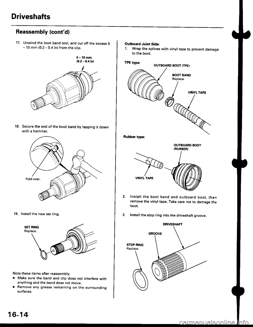
17.
Reassembly (cont'dl
Unwind the boot band tool, and cut off the excess 5- 10 mm (0.2 - 0.4 in) from the clip.
5-10mm10.2 - 0.a inl
Secure the end of the boot band by tapping it downwith a hammer,
19. Installthe new set ring,
18.
Note these items after reassembly:. Make sure the band and clip does notanything and the band does not move.a Remove any grease remaining on thesurfaces.
interfere with
su rrou nding
16-14
Outboard Joint Sid.:
1. Wrap the splines with vinyl tape to prevent damageto the boot.
TPE tvDe:-. OUTBOARO BOOT ITPE)
BOOT BANDReplac€,
Rubber typ.:
Install the boot band and outboard boot, thenremove the vinyl tape. Take care not to damage theboot,
Install the stop ring into the driv€shaft groove.
DRIVESHAFT
>VINYL TAPE
VINYL TAPE