description HONDA CIVIC 1999 6.G Owner's Guide
[x] Cancel search | Manufacturer: HONDA, Model Year: 1999, Model line: CIVIC, Model: HONDA CIVIC 1999 6.GPages: 2189, PDF Size: 69.39 MB
Page 335 of 2189
![HONDA CIVIC 1999 6.G Owners Guide System Description
System Conneetors IEngine Compartment] (contd)
9!l - 00 Dl6Y5 {CvT}, Dl6Y8 onginol
v
C14,0*3
c139
cl20
c1{{}
c122
1 1-66 HONDA CIVIC 1999 6.G Owners Guide System Description
System Conneetors IEngine Compartment] (contd)
9!l - 00 Dl6Y5 {CvT}, Dl6Y8 onginol
v
C14,0*3
c139
cl20
c1{{}
c122
1 1-66](/img/13/6068/w960_6068-334.png)
System Description
System Conneetors IEngine Compartment] (cont'd)
'9!l - 00 Dl6Y5 {CvT}, Dl6Y8 onginol
v
C14,0*3
c139
cl20
c1{{}
c122
1 1-66
Page 337 of 2189

System Description
a
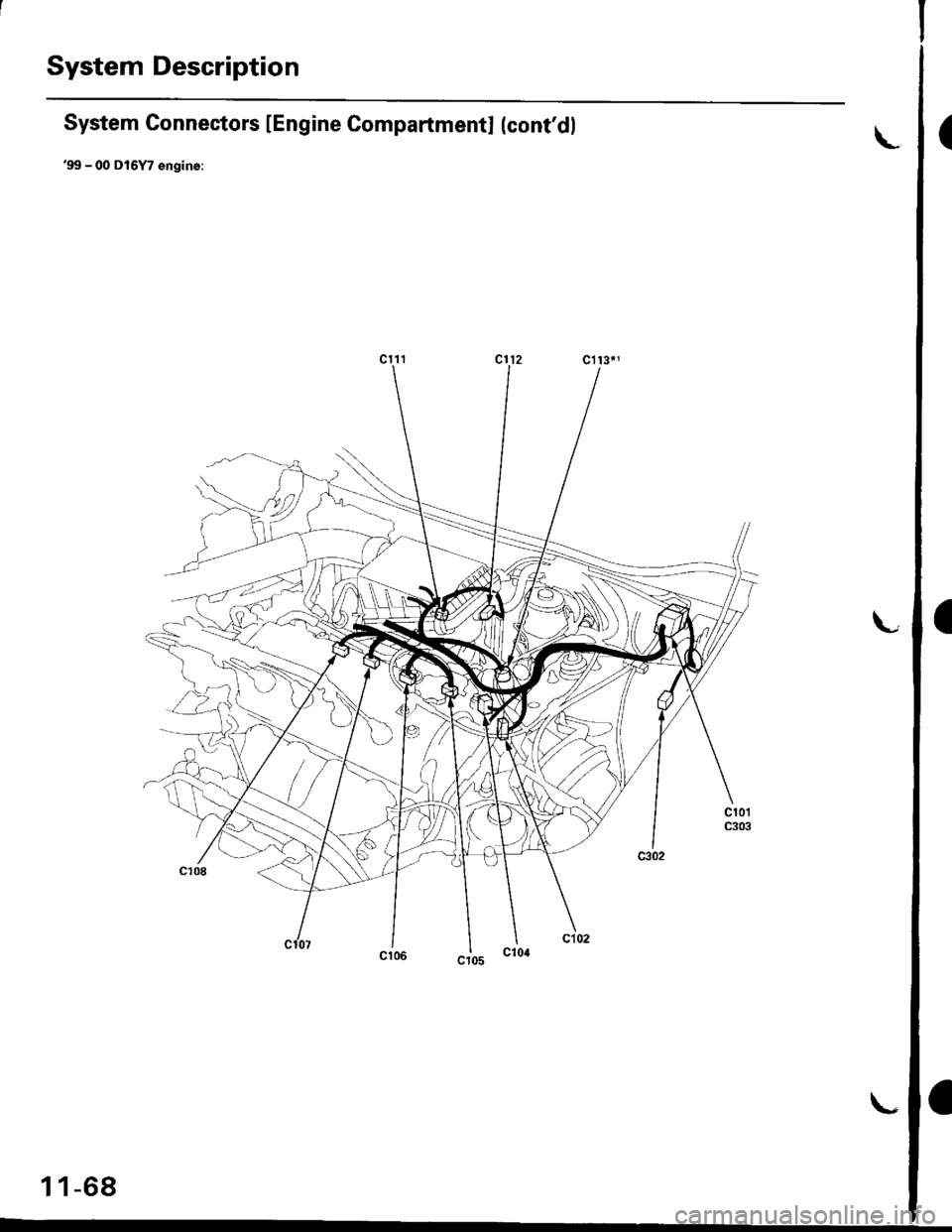
System Connectors lEngine Compartmentl (cont'dl
'99 - 00 D16Y7 engine:
\
I
1 1-68
I
Page 339 of 2189
![HONDA CIVIC 1999 6.G Owners Guide System Description
System Connectors [En gine Compartmentl (cont,d]
99 - 0O D16Y7 €ngin€:
11-70 HONDA CIVIC 1999 6.G Owners Guide System Description
System Connectors [En gine Compartmentl (cont,d]
99 - 0O D16Y7 €ngin€:
11-70](/img/13/6068/w960_6068-338.png)
System Description
System Connectors [En gine Compartmentl (cont,d]
'99 - 0O D16Y7 €ngin€:
11-70
Page 341 of 2189
![HONDA CIVIC 1999 6.G Owners Guide System Description
System Connectors [Engine Compartment] (contdl
816A2 engins:
11-72 HONDA CIVIC 1999 6.G Owners Guide System Description
System Connectors [Engine Compartment] (contdl
816A2 engins:
11-72](/img/13/6068/w960_6068-340.png)
System Description
System Connectors [Engine Compartment] (cont'dl
816A2 engins:
11-72
Page 343 of 2189
![HONDA CIVIC 1999 6.G Owners Guide System Description
System Connectors [Engine Gompartmentl (contd]
81642 enginoi
v
11-74 HONDA CIVIC 1999 6.G Owners Guide System Description
System Connectors [Engine Gompartmentl (contd]
81642 enginoi
v
11-74](/img/13/6068/w960_6068-342.png)
System Description
System Connectors [Engine Gompartmentl (cont'd]
81642 enginoi
v
11-74
Page 345 of 2189
![HONDA CIVIC 1999 6.G Owners Guide System Description
a
a
a
System Connectors [Dash and Floor]
(99 - fil models except D16Y5 engine with M/Tl
L
11-76
L HONDA CIVIC 1999 6.G Owners Guide System Description
a
a
a
System Connectors [Dash and Floor]
(99 - fil models except D16Y5 engine with M/Tl
L
11-76
L](/img/13/6068/w960_6068-344.png)
System Description
a
a
a
System Connectors [Dash and Floor]
('99 - fil models except D16Y5 engine with M/Tl
L
11-76
L
Page 347 of 2189
![HONDA CIVIC 1999 6.G Owners Guide System Description
System Connectors lDash and Floor] (contdl
(99 - 00 mod€ls oxc€pt Dl6Y5 ongine with M/T)
11-78 HONDA CIVIC 1999 6.G Owners Guide System Description
System Connectors lDash and Floor] (contdl
(99 - 00 mod€ls oxc€pt Dl6Y5 ongine with M/T)
11-78](/img/13/6068/w960_6068-346.png)
System Description
System Connectors lDash and Floor] (cont'dl
('99 - 00 mod€ls oxc€pt Dl6Y5 ongine with M/T)
11-78
Page 349 of 2189
![HONDA CIVIC 1999 6.G Owners Guide System Descriptions
System Connectors lFuel Pump]
(9!, - 00 models 6xcept Dl6Y5 ongino with M/T)
\(
I
c568
ffi
c565
E
c792
Different wires with the same color have been given a number suffix to disti HONDA CIVIC 1999 6.G Owners Guide System Descriptions
System Connectors lFuel Pump]
(9!, - 00 models 6xcept Dl6Y5 ongino with M/T)
\(
I
c568
ffi
c565
E
c792
Different wires with the same color have been given a number suffix to disti](/img/13/6068/w960_6068-348.png)
System Descriptions
System Connectors lFuel Pump]
('9!, - 00 models 6xcept Dl6Y5 ongino with M/T)
\(
I
c568
ffi
c565
E
c792
Different wires with the same color have been given a number suffix to distinguish them (for example, YEUBLKIand YEVBLK, are not the same).
O: Related to Fuel and Emissions System.- Connector with male terminals (double outline): View from terminal side- Connector with female terminals (single outline): View from wire side
c793
fr
NOTE: o
a
a
1 1-80
Page 355 of 2189

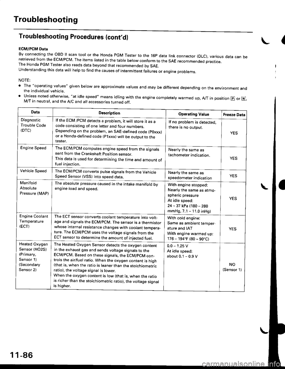
Troubleshooting
Troubleshooting Procedures (cont,dl
ECM/PCM Data
By connecting the OBD ll scan tool or the Honda pGM Tester to the l6p data link connector (DLC), various data can beretrieved from the EcM/PcM. The items Iisted in the table below conform to the sAE recommended practice.The Honda PGM Tester also reads data beyond that recommended bv SAE.understanding this data wil help to find the causes of intermittent fairures or engine probrems,
NOTE:
' The "operating values" given below are approximate values and may be different depending on the environment andthe individual vehicle.. Unless noted otherwise, "at idle speed,, means idling with the engine completely warmed up, Ay'T in position @ or E],M/T in neutral, and the Ay'C and all accessories turned off.
(
DataDescriptionOperating ValueFreeze Data
Diagnostic
Trouble Code(DTC)
lf the ECM /PCM detects a problem, it will store it as acode consisting of one letter and four numbers.Depending on the problem, an SAE-defined code (poxxx)or a Honda-defined code (Plxxx) will be outDut to therester.
lf no problem is detected,
there is no output.
YES
Engine SpeedThe ECM/PCM computes engine speed from the signalssent from the Crankshaft Position sensor.This data is used for determining the time and amount offuel injection,
Nearly the same as
tachometer indication.YES
Vehicle SpeedThe ECM/PCM converts pulse signals from the VehicleSpeed Sensor (VSS) into speed data.Nearly the same as
speedometer indicationYES
Manifold
Absolute
Pressure {MAP)
The absolute pressure caused in the intake manifold bvengine load and speed.With engine stopped:
Nearly the same as atmo-
spheflc pressure
At idle speed:
24 - 31 kPa (180 - 280
mmHg, 7.1 - 11.0 inHg)
YES
Engine Coolant
Temperature
(ECT)
The ECT sensor converts coolant temperature into volt_age and signals the ECM/PCM. The sensor is a thermistorwhose internal resistance changes with coolant temDera_ture. The ECM/PCM uses the voltage signals from theECT sensor to determine the amount of iniected fuel.
With cold engine:
Same as ambient temper,
ature and IAT
With engine warmed up:
176 - 194.F (80 - 90.C)
YES
Heated Oxygen
Sensor {HO2S)(Primary,
Sensor 1)(Secondary
Sensor 2)
The Heated Oxygen Sensor detects the oxygen contentin the exhaust gas and sends voltage signals to theECI\4/PCM. Based on these signats, the ECM/pCM con_trols the airlfuel ratio. When the oxygen content is high(that is, when the ratio is leaner than the stoichiometricratio), the voltage signal is lower.When the oxygen content is low (that is, when the ratiois richer than the stoichiometric ratio), the voltage signalis higher.
0.0 - 1.25 V
At idle speed:
about 0.1 - 0.9 V
NO(Sensor 1)
1 1-86
Page 358 of 2189

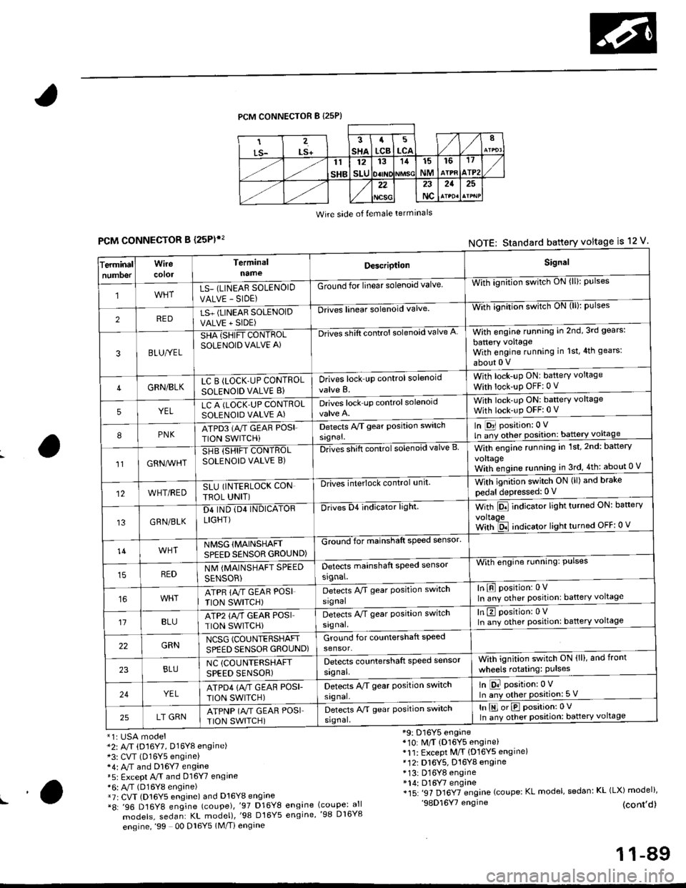
PCM CONNECTOR B {25P)
Wire side of {emale terminals
CONNECTOR B (25P)',
*1i USA model*2: A/T (D16Y7, Dl6Yg engine)*3: CVT (D16Y5 engine)*4: M and Dl6Y7 engane*5: Except A.rT and 016Y7 engine*6: A,/T (D16Y8 engine)*7r CVT (D16Y5 engine) and D16Y8 engine*8: '96 D16Y8 engine (coupe),'97 D16Y8
models, sedan: KL model),'98 Dt6Y5
engine,'99 00 Dl6Y5 1M/Ti engine
*9: D16Y5 engine*10: M/T (D16Y5 engine)*11: Except M/T {D16YS engine}*12i D16Y5, D16Y8 engine* 13: D16Y8 engine*14: D16Y7 engine*15: '97 Dl6YTengine (coupe: KL model, sedan: KL (LX) model)''98D16Y7 engine (cont,d)engine (coupe: allengine,'98 D16Y8
FCMNOTE: Standard battery voltage is 12 v'
erminalTnumoer
Wirecotol
TerminalnameDescriptionSignal
1LS_ (LINEAR SOLENOID
VALVE - SIDE)
Ground for linear solenoid valveWii-ignnion switctr oN {ll}: pulses
2REDLS+ (LINEAR SOLENOIDVALVE + SIDE)
-Drii6l linear solenoid valveWith ignilion switch uN (lll: pulses
3BLU/YEL
SHA {SHIFT CONTROLSOLENOID VALVE A)
-Drives shift control solenoid valve AWith engine running in 2nd,3rd gears:
battery voltageWith engine running in 1st,4th gears:
about 0 V
4GRN/BLKLC B (LOCK'UP CONTROL
SOLENOID VALVE B}Drives lock up control solenoid
valve B.
With lock-up ONI battery voltage
With lock-up OFF:0 v
5YELLC A (LOCK.UP CONTROLSOLENOID VALVE A)Drives lock up controlsolenoidWith lock-uP ON: baftery voltage
With lock-up OFFi 0 V
8PNKATPD3 (NT GEAR POSI.
TION SWITCHi
Detects Py'T gear Position switch
signal.
In [D31 position: 0 V
ln ;y other position: battery voltage
1lGRN^lr'HT
SHB (SHIFT CONTROLSOLENOID VALVE B)DnGs shift conttol solenoid valve BWith engine running in 1st,2nd: battery
vo|taqeWith;ngine running in 3rd,4th: about 0 V
12WHT/REDSLU (INTERLOCK CON
TBOL UNIT)
-DlivEilite'lock control,rnit.With ignition switch ON (ll) and brake
pedal depressed: 0 V
13GRN/BLK
D4 IND (D4 INDICATORLIGHT)
Drives D4 indicator light.With Pll indicator lrght turneo urr: oarterv
voltaoeWith ld indicator light turned OFF: 0 v
14WHTNMSG {MAINSHAFTSPEED SENSOR GROUND)
GZiiI'for mainshaft speed sensol
With engine running: Pulses
In E position: 0VIn any other position: battery voltage
REDNM {MAINSHAFT SPEED
SENSOR)
Detects mainshaft speed sensor
srgnal.
ATPR {M GEAR POSI
TION SWITCH)
Detects M gear Position switch
signal
't1BLUATP2 {A/T GEAR POSITION SWITCH)
Detects A/T gear Position switch
signal.
In E position: 0VIn any other position: battery voltage
22GRNNCSG (COUNTERSHAFT
SPEED SENSOR GROUND)Ground for countershaft speed
sensor.
23BLUNC (COUNTERSHAFT
SPEED SENSOR)
Detects countershaft speed sensor
signal.
Vvith ignition switch ON (ll), and front
wheels rotating: Pulses
24YELATPD4 {M GEAF POSI-
TION SWITCH)
Detects M gear Position switch
signal.
ln E position:0 VIn any other position: 5 V
25LT GRNATPNP (A"/T GEAR POSITION SWITCH)
Detects A/T gear Position switch
srgnal,
In E orE position:0 V
In any other position: battery voltage
!a
11-89