ac system HONDA CIVIC 1999 6.G Workshop Manual
[x] Cancel search | Manufacturer: HONDA, Model Year: 1999, Model line: CIVIC, Model: HONDA CIVIC 1999 6.GPages: 2189, PDF Size: 69.39 MB
Page 1896 of 2189
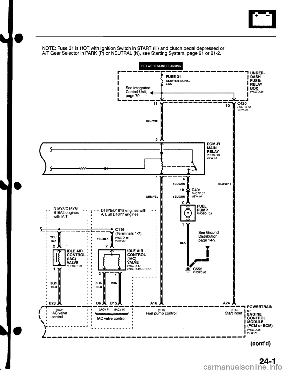
NOTE: Fuse 3l is HOT with lgnition Switch in START (lll) and clutch pedal depressed or
A'/T Gear Selector in PARK (P) or NEUTRAL (N), see Starting System, page 21 or 21-2.
FUSE 31SIAilEfi SIGT{AL7.fi
UNDER.DASHFUSE/RELAYBOXPHOTO 58See ldeoratodControl Unit,page 70.
1110c420
vtEv,/ 53
PGM-FIMAINRELAY
vlEW 18
-:f]'" l;;;,b"YEUG8N
I
vtEw 40
i fli,i{ry;g:l lr R;::i8i3ll:13rffi:-''
'r
I H[f#'-
il |r'ru*
ljT-.i|ff
| - Friofo 1id | | I | Plioio {- n, 1 Y LJirJ-J plroio 4s tot6v7, I I G552'lt:i:PHotosa
I [ :: ! 'l r------' er-xl iiar-xfi onrl
i*"1 l:"'l I :
: I i: I I :
iazsA ii eoA ers|' , ltol lcql.I POWERTRAIN,a1F--X-lo"i"r t, "u*t : (FLF)
! , lAcvatve I i rq;.,.-...,; : Fu€r pump controt s"liii'p", ! EHc,le:;w, ruEr PqrrPlJtrIulI , connot :; IAC vatve controt , ! CONTROL
(cont'd)
24-1
Page 1900 of 2189
i--I,*.;----l
I I ffl* s€€ Pow€' I
!---h=js:q-l
r'1ltii*",
! il"Jiisa"
;ll
i-[*-*"".""--l
! @ffi[+[ffI. !
! Ir6rer i
L--L-,sr@lc5Y
UNDER.DASHFUSE/RELAYBOXPHO|O 58
GAUGEASSEMBLY
;------- USA -------,
see ly'c i S"" :Compressor , See Charging ;Controts , Fans System , POWERTRAIN-
li*t*rr,, ".o^.of, i """f """,tr' i tff'$fit!
Tl,!,
"0o -;;l
i ;;l ^*l i
n"""j.F,rH;
Irs I A17 A :A2oA moA :
,'-----ri;)---7ol------T-;;l----,il--i-----'r,' r',lrr- di-ritror lvc "orip-E""or : Fa; ;;iror eldiinit : II clutci relay conlrcl InPd I\tri---"---i t!9--. i-;ter";--I i{r,*+-i 1s"'*.'lr I t'lc : EGR control : : Atternator I A[emator ]'. I KS : requ6st ; solenoid ; VSS ' control , FR Ia , inDut : inout , \iave control , inpul , sional ' sianal I, , (Ks) i i*"1 , (Esor, _jt,__.j-_JgL-.j__ ,^:_j3------- --- --- -- -.4- -- -- -,1-- - -
i"fiti".,ff:l i"111 iffilifili"F"l
i*l i + i I i
"+
i-"1 :''"1T'See LiC , I ' See vehicle t--'---'-'
ComOressor , 2 ^C142 : SpeedContiofs | | PHoro124 i Sensor
i ft> i :"::l
' ".o
|
",o,o,,0
i lisi: 3i&S**n,"n
i Lti-t i i rh;ry,'s;3+r"" i
: I ""n,".*l iiltll lS'"",.?^8"'$lli'til ""n'"'*! iil-il]J5ff#f."ruuu
i ll.,*'o.* ! *o,o,no i i l'.lT- seecround
: FflSI8$" i Btr"lifiiJ}': i i *i[ Bi,i"EL'""
; f lJffi""' !**;' i i":-lei'u!,7,,"
ws{u'
(cont'd)
24-5
Page 1907 of 2189
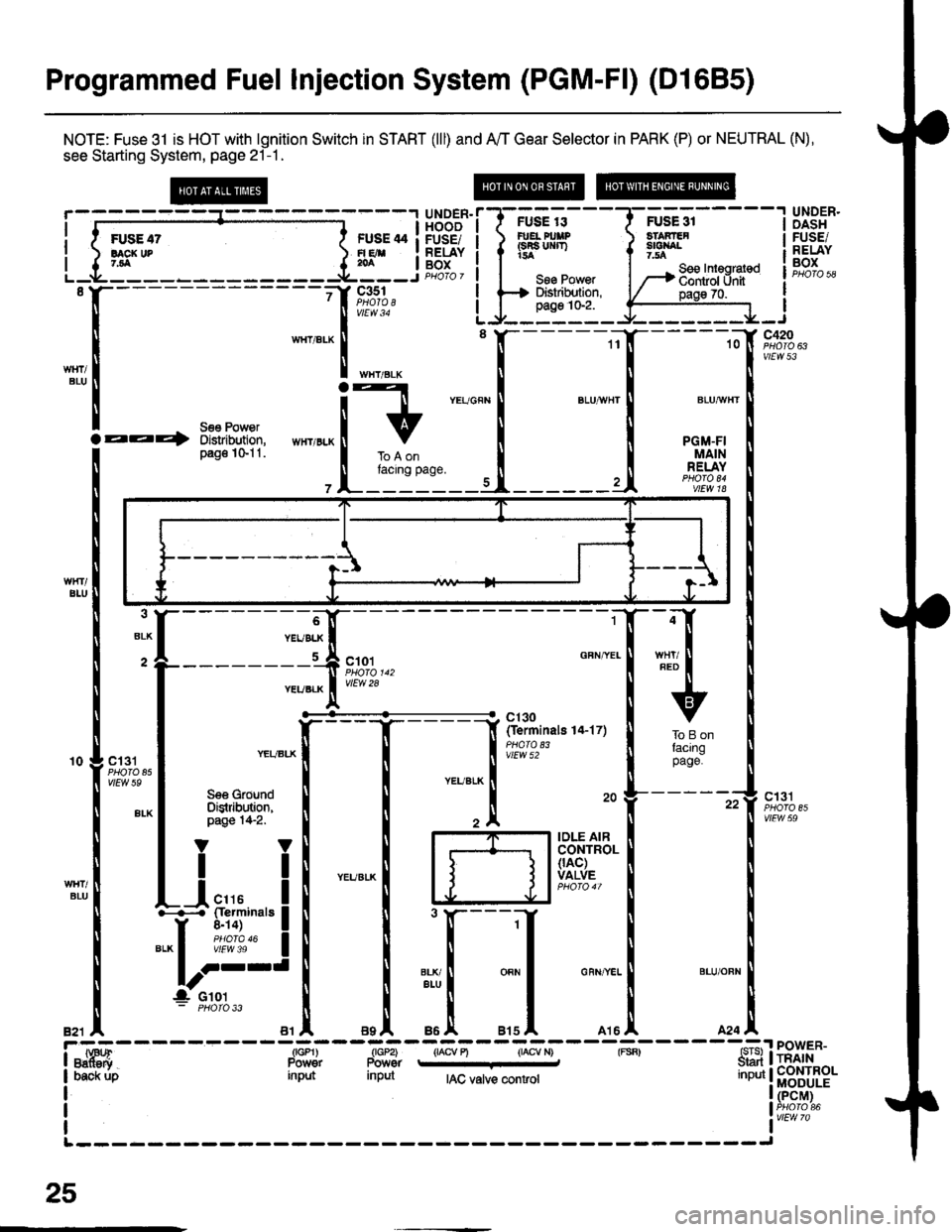
Programmed Fuel Injection System (PGM-F|) (D1685)
NOTE: Fuse 31 is HOT with lgnition Switch in START (lll) and A'/T Gear Selector in PARK (P) or NEUTRAL (N),
see Starting System, page 21-1 .
@
ii6iir-
- -TFU'E;--- - -
I gI3'5"
y#*i[HtF{,iiH.frIHHi Jiffi" !['.iF{,$SNALr5a Y 7.54| - See Inleqrat€dSse Pow€r | --+ ffii;l'i; -- | Phoro 58i ffi ffi:- |EHF? i I
p--',b"
I iffij*,**.,* iFE^l
SACI( UP7,ta
'[-------------'[&T:1,
L.[E"Jj!i_.f;ff:]_j
*L:*
ilTrr,*ii "",""[*=
{ {-
--
;[n*n-
--ftr-'lf
tlGFNYEI
T HI I
rv
J &l?3.,"","'o-,rr ! ,o"on
! #""?,* I
'rT#
*"ll
'fi-----n
h,T5$B.I
J J lvA!::, !
[--iI I
!tl
I onr I can ver- | er-u onn
Itt
A arsl rrsl a24
;t--7;,i----&;-----{IAC valve mnt.ol
;YN
IT/U
ll
v
ToBonlaclngpage
4
FED
I T------i:il;
,oln,.r I """-f-T:
-l-Lri | |d
l
wtl
Iil
i-,"ffifi
- - - - - - -- - -;s,nl - -ffi'J -.'"-
I Oac* rjp input input A
I
I
I|.-------
{F;H:{"
I
I
-"1
,,..!.'-^-*'! PowER-
f,mihHin.
I (PCM)
lif''?;"
25
BIU
Page 1912 of 2189
@----t UNDER.
I t FUSE 2s I p.4:!
| ) Iff" ses Power | ;"Eiii
I l------+ 3l'i:?'J:" tF,%.,L--*----il--l-J -
'o Y F;%.YELI v/Ew 55
f
--- - - - - - - - - - -;f '-iminats tz'zo1
I c+ lv'rwto
Y r--'1r-:-----'l GAUGE
see Power ! f* l"?i*,".. ! f,s";"ty"ttDisiribution, I , | vtEwTlpass10'6
i @$eFH,t* i
! T16r I
see see !y'c see I I
-ruil |See Startrnq ComDressor Charorno L--V---J----JFans System Conliols Syste-m - C5 y
I I I I
"".11-lro,..
| | | | o"no"n!f[?iSuo
GUN
I
BLUVHT
I
BLKnEo
I
GRNFED
f sVC131
*o I o, .1. o', ,l o.o .l
o"*o*l i[?1o"*
,r---U,a"i---strF-*-*"r"tr8*i-#%,.----;w;,---lneffi [it^'" tan control control ciutch reiay control Input | (pCM) -._ | puoroear AJc Atternaror Atternator l. iir*.i VSS rsquest FR controt I
i '[g3l i"R8!, ",gl,1o "'11'%, IrL------ --------Jc23 ll, l27Y "ur "rX
tlllBtUw}rI
I
BLU,FEo
I
w8r RED I wxr onr I
IIIIYYYY
See Vehicle See A,/C -'-dSpeedSensor Compressor(vss) contiot 3i:,""I"'n'"n
(cont'd)
25-5
I
Page 1922 of 2189
Gruise Control (cont'd)
- How the Circuit Works
The cruise control system uses mechanical and
electrical devices to maintain the car's sDeed at a
setting selected by the driver.
System Description
The cruise control unit receives command signals
from the crurse control main switch and the cruise
control SeVResume switch. With the ignition switch
in ON (ll) or START (lll), voltage is provided to the
cruise control main switch through fuse 14. When
you push the switch to ON, power is provided to the
cruise control unit and the brake switch.
The cruise control unit receives information about
operating conditions from the brake switch, the
vehicle speed sensor (VSS), and the clutch switch
(manual transmission) or the A,/T gear position
switch (automatic transmission). The cruise control
unit then sends signals to the cruise control actuator
which regulates the throttle position to maintain the
selected speed. The conlrol unit compares the
actual speed of the car to the selected speed. The
control unit then uses the result of that comoarison
to open or close the throttle.
The brake switch releases the system's control of
the throttle at the instant you press on the brake
pedal. The switch sends a signal to the control unit
by removing power from the normally closed brake
input (GRY wire), and providing power at the
normally open brake input (GRN/vVHT wire). The
control unit responds by allowing the throttle to
close. The clutch switch or the A,/T gear position
switch sends a "disengage" signal to the control unit
that also allows the throttle to close.
The cruise control system will set and automatically
maintain any speed above 25 mph (40 km/h). To set
it, make sure the main switch is on and the switch
indicator is on. Then, after reaching the desired
speed, press the SET switch. This sends a "set"
signal to the cruise control unit which, in turn,
controls the cruise control actuator to maintain the
set speed.
When you push the SET switch and the cruise
control system is on, the "cruise control" ON
indicator lights up.
34-4
(
You can cancel the cruise control system by
turning the main switch off . This removes power to
the control unit and erases the set speed from
memory. lf the system is disengaged temporarily
by the brake switch, or clutch switch, and the car's
speed is still above 25 mph, press the resume
switch: the car will automatically return to the
previously set speed.
For gradual acceleration without pressing the
accelerator pedal, push the RESUME switch and
hold it there. This will send an "acceleration" signal
to the control unit. When you release the switch, the
system will be reprogrammed for the new speed. To
slow the car down. oush the SET switch in and hold
it there. This sends a "deceleration" signal to the
control unit, causing the car to coast. When the
desired speed is reached, release the SET switch.
This reprograms the system tor the new speed.
Refer to the Service Manual (Section 23, Electrical)
tor specific tests or troubleshooting procedures.
(
a
Page 1939 of 2189
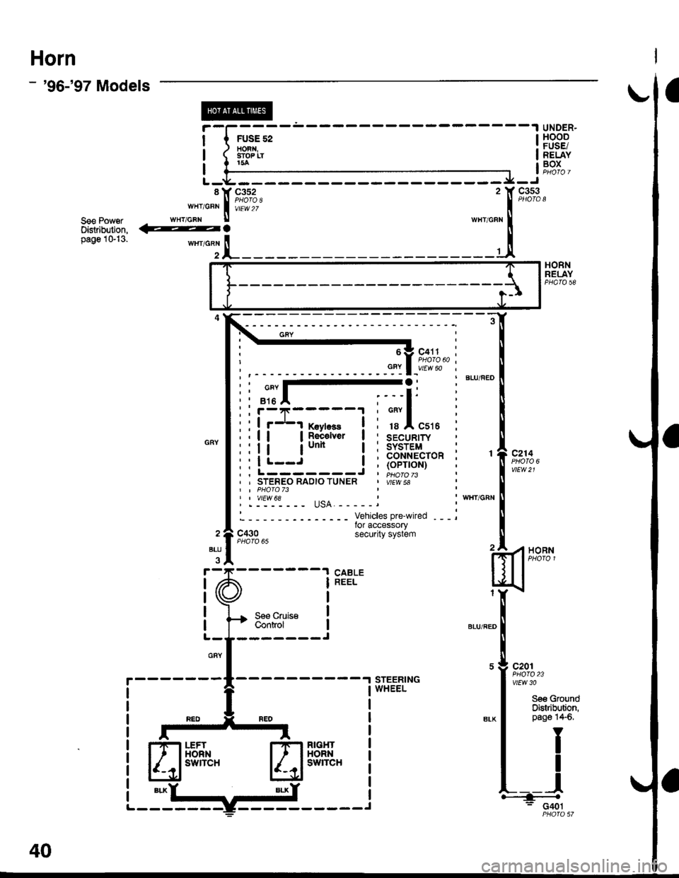
Horn
- '96-'97 Models
UNDER.HOODFUSE/RELAYBOX
c353PHOTOs
See PowerOistribution,pag610-13.""^T.!,-
HORNRELAYPHA|O 58
c214
vtEw21
BLU/FEO
1
VHT/qRN
I1
WHT/qRN
: :i-I:::--li i ! !'-'! fevtess
! a;fi."*
,,lr--J I::.-------J. , STEREO RAOIO TUNER
| | vtEw 68
HORN
l
h: c4o1PHQ|A 57
c430
Sse CruiseControl
Vehicles pre-wired ---lor accessorysecurity system
BLU
GBY
------- J
- -.! STEERINGWHEEL
6 g c411
| _vtEw 60
a,---li
cnv I
18 A C516
sEcuRtwSYSTEMCONNECTOR(oPTroN)PHO|O 73VEW 5A
40
Page 1941 of 2189
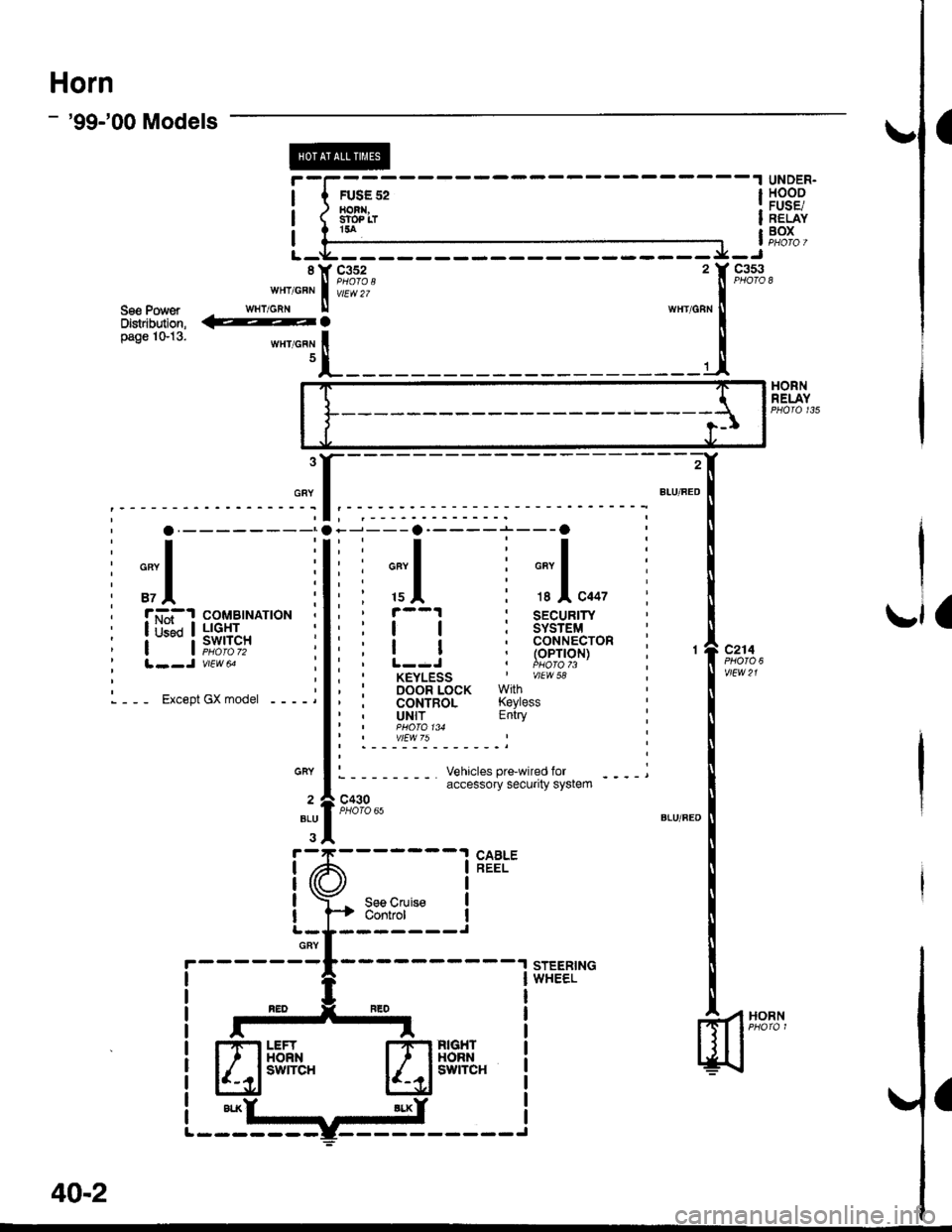
Horn
- '99-'00 Models
FUSE 52HORI,SfOP LTt5a
UNDER.HOODFUSE/RELAYBOX
HORNRELAY
2
BIU/FED
Ior
GRY
.,1 ,
J---a-----r---O
i ;l i ;,1...,' r--1 : SECUR|TY:ll:sYsrEM,ia,coNNEcroR' ! ! (oPrloN), L--J , i!,o!o 73, KEYLESS I vlEw 58
: DooR LocK withi coNTRoL Kevless, UNIT EntryI PHOIO 134I vtEw 75
i o.--------;
:T:' cnvl :
i"l ii ri-'--.| coMBtNATtoN
: lrft ! !',f,11" I' | | puotozz :', l--J vttw u ;
i--- Er""pt ex.ooer ----j
c214
v|EW21
c430PHOTO 65
Vehicles pre-wired foraccessory security system
STEERINGWHEEL
CABLEREEL
.l
I
I
I
ISee CruiseControl
GRY
ELU
I
a\
I
GRY
HORN
---------^1
niffil"a!m"
40-2
Page 1942 of 2189
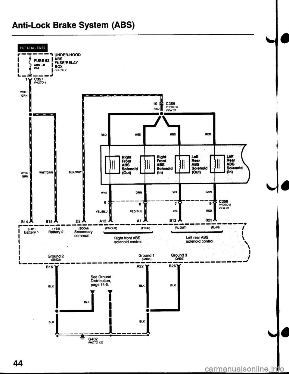
Anti-Lock Brake System (ABS)
UNDER.HOOD
H'.'"" ii[*:'*"
1
GFN
c357PHOTO 4
c359PHO|O 610
BEO
Grqlnd 2{GX!2)
l"l Fi* :l :l
!Ji I-J
.-L-----
i il
TPHOIO 125
44
Page 1944 of 2189
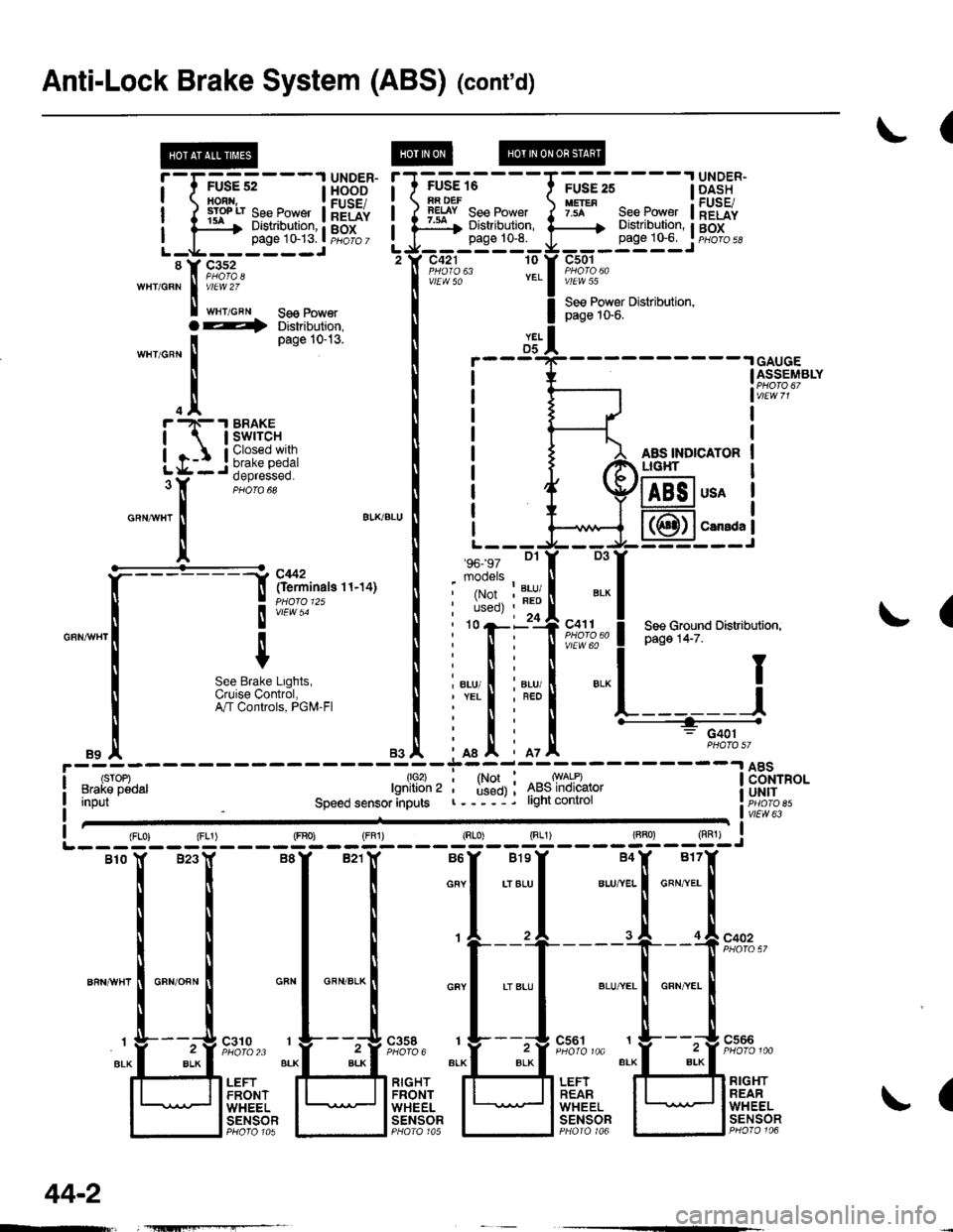
Anti-Lock Brake System (ABS) (cont'd)
(
FUSE 16iA DEFlEtsY See Power:ar Distribution,page 10-8.
c421 10
vlEW 50
'96- 97 Dl
mooels
.I UNDER-
page 1G6. I pHoro 5d
c501
vlEW 55
See Power Distribution,page 1S6.
AAS INDICATORLIG}IT
!'-r;us?;---l H5BE"
ilrryilrfi#ftilHriL-g------JL-g------J'tr F,1%'wHr/GRN I v/El.V 2Z
I t"r,o"" se€ Power
YELD5GAUGEASSEMBLY
usA
CarsdaI
(
D3
', ',i:,tr?""" ! P"g" t+-z".r',
*
! see cround Distributiofl,
".., I i"., I ".-l I;nl
iffit L------J
' n : G401
mI iot
T1*l ^*ry*l:-------l 8Bi"o.' used) ; 4ts5lnolcalor i UH|Tr----j. light conlrol r. iicib ett,"LTfflo",Input
1lo2)lgnition 2
Speed sensor anputsvlEw 63
(
{FLo) {FL1) (FBo) {FF1) (Rr"o) Sg____gT]-__g,l-j
Blo lf B23Y B8Y B21lf B6Y BlsY B4X B17f
i i I i o""l .,",-ul u.,"..1 o"",'.. I
rrttl
| | | I ,l ,l .I of"on"
ll ll I ti
't---'+----"[ --f !'?'%,'
""n*",lo"no""l *"1 *"*-l *"1 .'"."1 *,*.[ "**.I
I r L___t"" " t__t"." 1___!".""
"r.f_ "4::3' ;FJ,;::; ":f3:::1'' "lf-*i":''
t' ,.,Jtri"?r. ll;l]flffi lFli.ft. lU]flqtfl
l l"#tgl I lt5T8?l I lt"F"Ti?l I lt;Tt?f
O--t Distribution,
'n"r,o^n
I
Page 10-13'
.trr -N- .I BRAKE
| | swrrcH
igr:*
o"ntr"r
!
a'KBLU
It
""*[:-l
ftff^"n"o''''ot
I
", I
m;r""#,usi:",
".1
44-2
Page 1945 of 2189
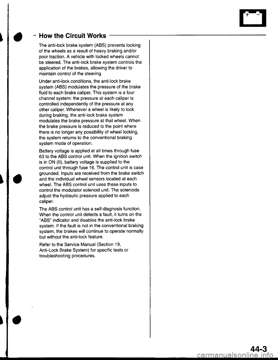
- How the Circuit Works
The anti-lock brake system (ABS) prevents locking
of the wheels as a result of heavy braking and/or
poor lraction. A vehicle with locked wheels cannot
be steered. The anti-lock brake system controls the
application of the brakes, allowing the driver to
maintain control of the steering.
Under anti-lock conditions, the antilock brake
system (ABS) modulates the pressure of the brake
tluid to each brake caliper. This system is a four
channel system: the pressure at each caliper is
controlled independently of the pressure al any
other caliper. Whenever a wheel is likely to lock
dunng braking, the anti-lock brake system
modulates the brake oressure at that wheel. When
the brake pressure is reduced to the point where
there is no longer any possibility of wheel locking,
the system returns to the conventional braking
system mode of operation.
Battery voltage is applied at all times through fuse
63 to the ABS control unit. When the ignition switch
is in ON (ll), battery voltage is supplied to the
control unit through fuse 16. The control unit is case
grounded. Inputs are received from the brake switch
and the individual wheel sensors located at each
wheel. The ABS control unit uses these inputs to
control the modulator solenoid unit. The solenoids
adjust the hydraulic pressure applied to each
calioer.
The ABS control unit has a self-diagnosis function.
When the control unit detects a fault, it turns on the"ABS" indicator and disables the anti-lock brake
system. lf the fault is not in the conventional braking
system, the brakes will continue to operate normally
but without the anti-lock feature.
Refer to the Service Manual (Section '19,
Anti-Lock Brake System) for specific tests or
troubleshooting procedures.
44-3