ac line HONDA CIVIC 1999 6.G Service Manual
[x] Cancel search | Manufacturer: HONDA, Model Year: 1999, Model line: CIVIC, Model: HONDA CIVIC 1999 6.GPages: 2189, PDF Size: 69.39 MB
Page 190 of 2189
t
Valve Guides
Replacement
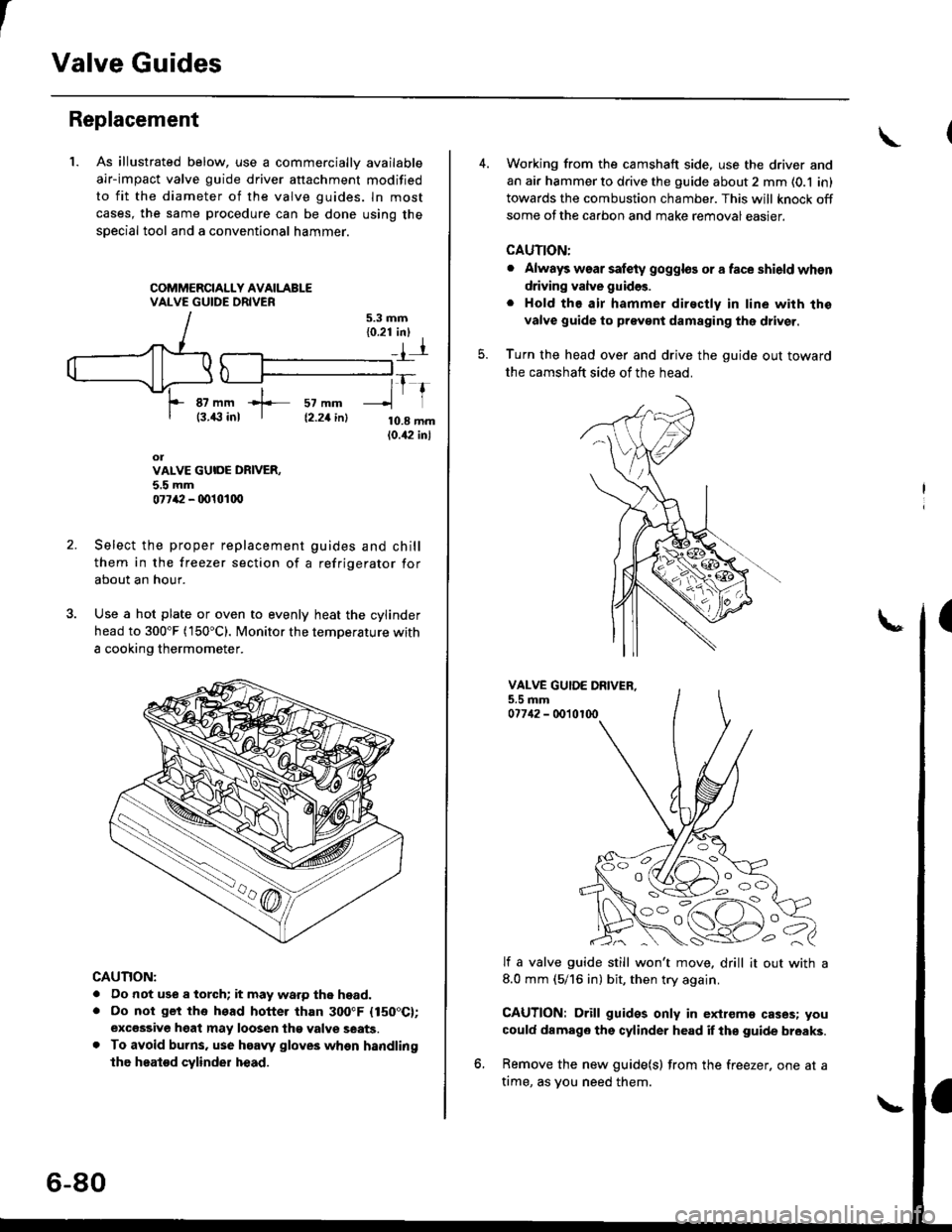
1. As illustrated below, use a commerciallv available
air-impact valve guide driver attachment modified
to fit the diameter of the valve guides. ln most
cases, the same procedure can be done using the
sDecial tool and a conventional hammer.
COMMERCIALLY AVAILABLEVALVE GUIDE DRIVER
87 mm -L- sz mm(3.43 inl I tz.zr int
rE-tt
10.8 mm10.42 inl
olVALVE GUIOE DRIVER,5.5 mm077,P - 0010100
Select the proper replacement guides and chill
them in the freezer section of a refrigerator for
about an hour.
Use a hot plate or oven to evenly heat the cylinder
head to 300"F (150"C). Monitor the temperature with
a cooking thermometer.
CAUTION:
. Do not use a torch; it may warp tho head.. Do not get tho head hotter than 300"F {150"C};excesgive heat may loosen thg valve seats.. To avoid burns. use haaw gloves whon handling
the heatod cylinder head.
6-80
Working from the camshaft side, use the driver and
an air hammer to drive the guide about 2 mm (0.1 in)
towards the combustion chamber. This will knock off
some ofthe carbon and make removaleasier.
CAUTION:
. Always wsar safety goggles or a face shield whsn
driving valve guides.
. Hold the air hammer dir€ctly in line with the
valve guide to prevont damaging thg dtiver.
Turn the head over and drive the guide out toward
the camshaft side of the head.
VALVE GUIOE DRIVER,5.5 mm077{2 - 0010100
lf a valve guide still won't move. drill it out with a8.0 mm (5/16 in) bit, then try again.
CAUTION: Drill guides only in extreme cases; you
could damago the cylinder head if ths guide br6aks.
Remove the new guide(s) from the freezer, one at a
time, as vou need them.
-:^-,65i^q
NNSp-<
Page 193 of 2189
Rocker Arms
lnstallation
1.
2.
3.
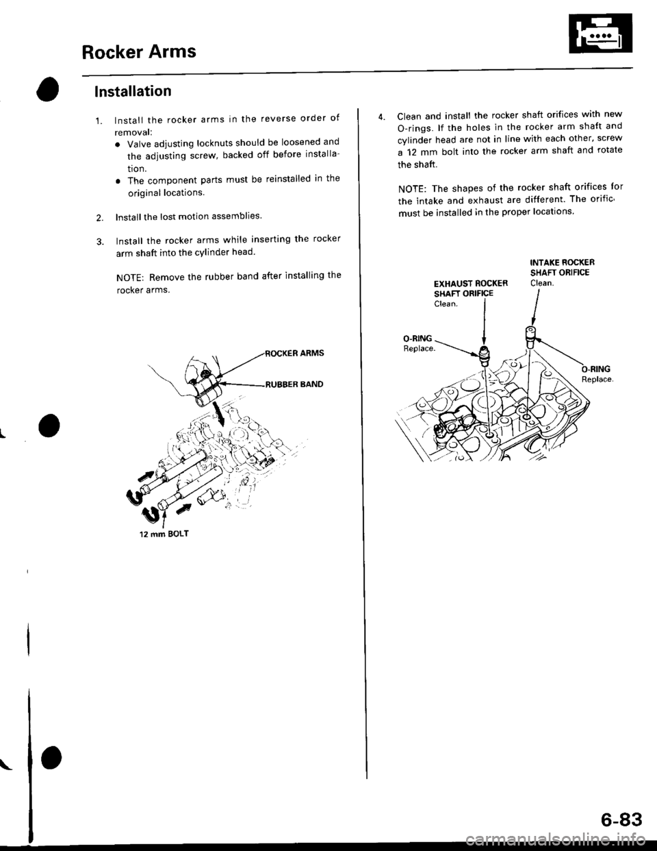
lnstall the rocker arms in the reverse order of
removal:
. Valve adjusting locknuts should be loosened and
the adiusting screw, backed off before installa-
tron.
. The component parts must be reinstalled in the
original locations.
lnstall the lost motion assemblies.
lnstall the rocker arms while inserting the rocker
arm shaft into the cylinder head
NOTE: Remove the rubber band after installing the
rocker arms.
12 mm BOLT
\
6-83
4. Clean and install the rocker shaft orifices with new
O-rings. lf the holes in the rocker arm shaft and
cylinder head are not in line with each other, screw
a 12 mm bolt into the rocker arm shaft and rotate
the shaft.
NOTE: The shapes of the rocker shaft orifices tor
the intake and exhaust are different. The orific'
must be installed in the proper locations.
INTAKE ROCKER
SHAFT ORIFICE
EXHAUST ROCKER Clean
SHAFT ORIFICE
O.RING
O
Page 219 of 2189
Piston RingsCrankshaft Oil Seal
Alignment (cont'dl
TOP RING ---.>
SECOND RING >
MARK
,a-)
/\_4
o,.r^o( qffi<--sPACER
\Z-.
v
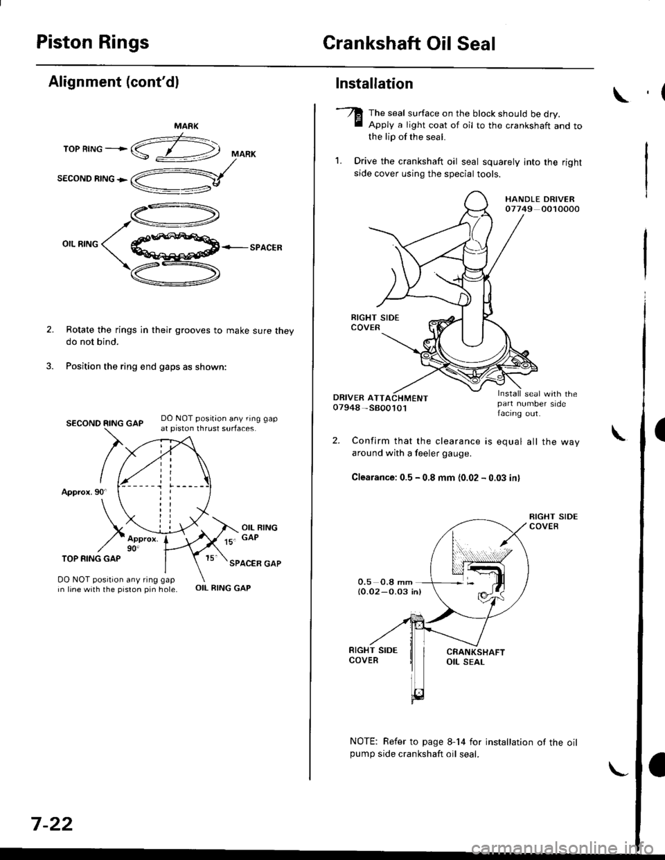
Rotate the rings in their grooves to make sure theydo not bind.
Position the ring end gaps as shown:
DO NOT position any ring gapat piston thrust surfaces.
DO NOT position any ring gapin line with the piston pin hole.OIL RING GAP
SECOND RING GAP
Approx.90
TOP RING GAP
7-22
Installation
The seal surface on the block should be dry.Apply a light coat of oil to the c.ankshaft and tothe lip of the seal.
1. Drive the crankshaft oil seal squarely into the right
side cover using the special tools.
HANDLE DRIVER07749 0010000
seal with thepan number sidefacing out.
Confirm that the clearance is equal all the way
around with a feeler gauge.
Clearance:0.5 - 0.8 mm (0.02 - 0.03 inl
NOTE: Refer to page 8-14 for installation of the oilpumo side crankshaft oil seal.
,(
\
Page 220 of 2189
PistonsGrankshaft
lnstallation
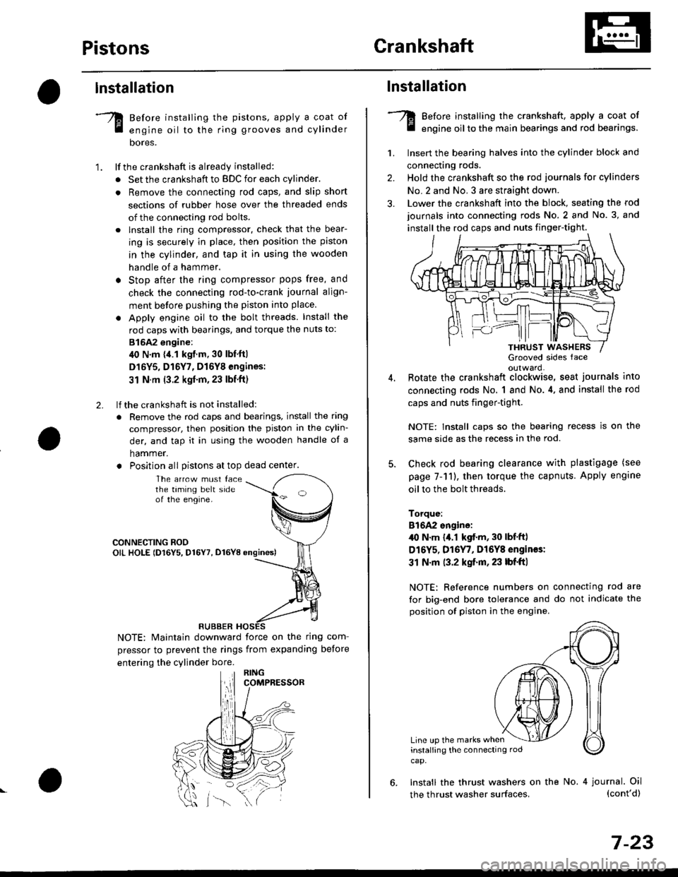
Before installing the pistons, apply a coat of
engine oil to the ring grooves and cylinder
bores.
lf the crankshaft is already installed:
. Set the crankshaft to BDC for each cylinder.
. Remove the connecting rod caps, and slip short
sections of rubber hose over the threaded ends
of the connecting rod bolts.
. lnstall the ring compressor. check that the bear-
ing is securely in place, then position the piston
in the cylinder, and tap it in using the wooden
handle of a hammer.
o Stop after the ring compressor pops free, and
check the connecting rod-to-crank journal align-
ment before pushing the piston into place
. Apply engine oil to the bolt threads. Install the
rod caps with bearings, and torque the nuts to:
815A2 engine:
40 N.m {,1.1 kgf.m, 30 lbf'ft|
D16Y5, D16Y7, D16Y8 engines:
31 N.m (3.2 kgf'm,23 lbf'ft)
lf the crankshaft is not installed:
. Remove the rod caps and bearings, install the ring
compressor, then position the piston in the cylin-
der, and tap it in using the wooden handle of a
hammer.
. Position all Distons at top dead center.
1.
2.
The arrcw must facethe taming belt sideof the engine.
CONNECTING ROOOIL HOLE lD16Y5, D16Y7, D16YB ongines)
NOTE: Maintain downward force on the ring com-
pressor to prevent the rings from expanding before
entering the cylinder bore.
RUBBER
,lll
lnstallation
Before installing the crankshaft, apply a coat of
engine oil to the main bearings and rod bearings.
Insert the bearing halves into the cylinder block and
connecting rods.
Hold the crankshaft so the rod journals for cylinders
No.2 and No. 3 are straight down.
Lower the crankshaft into the block, seating the rod
journals into connecting rods No. 2 and No. 3, and
install the rod caps and nuts finger-tight.
1.
2.
3.
5.
Grooved sides faceoulward.Botate the crankshaft clockwise, seat journals into
connecting rods No, 1 and No.4, and install the rod
caps and nuts finger-tight.
NOTE: Install caps so the bearing recess is on the
same side as the recess in the rod.
Check rod bearing clearance with plastigage (see
page 7-11), then torque the capnuts. Apply engine
oil to the bolt threads.
Torque:
816A2 sngine:/l{, N.m {a.l kgf.m, 30 lbf'ftl
D16Y5, D16Y7, Dl6Y8 engines:
31 N.m (3.2 kgf.m, 23 lbf'ft|
NOTE: Reference numbers on connecting rod are
for big-end bore tolerance and do not indicate the
position of piston in the engine.
Line up the marks wheninstalling the connectrng rod
cap.
6. Install the thrust washers on the No. 4 journal. Oil(cont'd)
7-23
the thrust washer surfaces,
Page 221 of 2189
Crankshaft
Installation (cont'd)
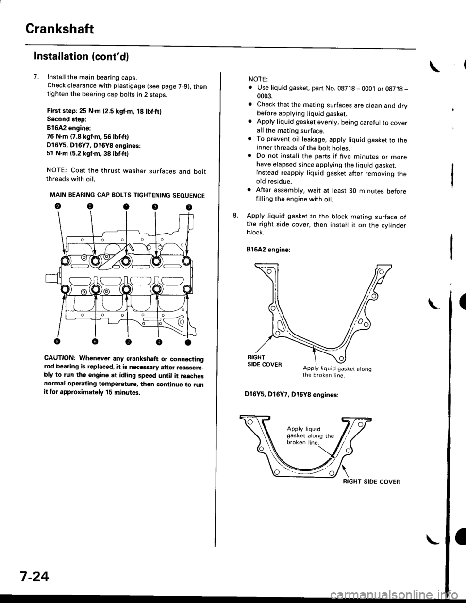
7. Installthe main bearing caps.
Check clearance with plastigage (see page 7-9), thentighten the bearing cap bolts in 2 steps.
First step: 25 N.m {2.5 kgf.m, 18 lbf.ft)
Second stop:
B1642 engine:
76 N.m {7.8 kgf.m, 56 lbf.ft)
D16Y5, D16Y7, D16Y8 engines:
51 N.m (5.2 kgf.m, 38 lbf.ft)
NOTE: Coat the thrust washer surfaces and boltthreads with oil.
MAIN BEARING CAP BOLTS TIGHTENING SEOUENCE
oocoo
CAUTION: Whenever any crankshaft or connectingrod bearing is replaced, it is necGssary after reassom-bly to run the engine at idling spe6d until it reachesnormal operating temperature, than continue to runit for approximately 15 minutos.
:V fr\-/.---\-/.-
7-24
NOTE:
. Use liquid gasket, part No. 08718 - 0001 or08718-0003.
. Check that the mating surfaces are clean and drybefore apptying liquid gasket.
. Apply liquid gasket evenly, being careful to coverall the mating surface.. To prevent oil leakage, apply liquid gasket to theinner threads of the bolt holes.. Do not install the parts if five minutes or morehave elapsed since applying the liquid gasket.
Instead reapply liquid gasket after removing theold residue.
. After assembly, wait at least 30 minutes beforefilling the engine with oil.
L Apply liquid gasket to the block mating surface ofthe right side cover, then install it on the cylinderblock.
Bl6A2 engine;
Apply tiquid gaslet alongthe broken line.
D16Y5, D16Y7, D16Y8 engines:
RIGHT SIDE COVER
Page 222 of 2189
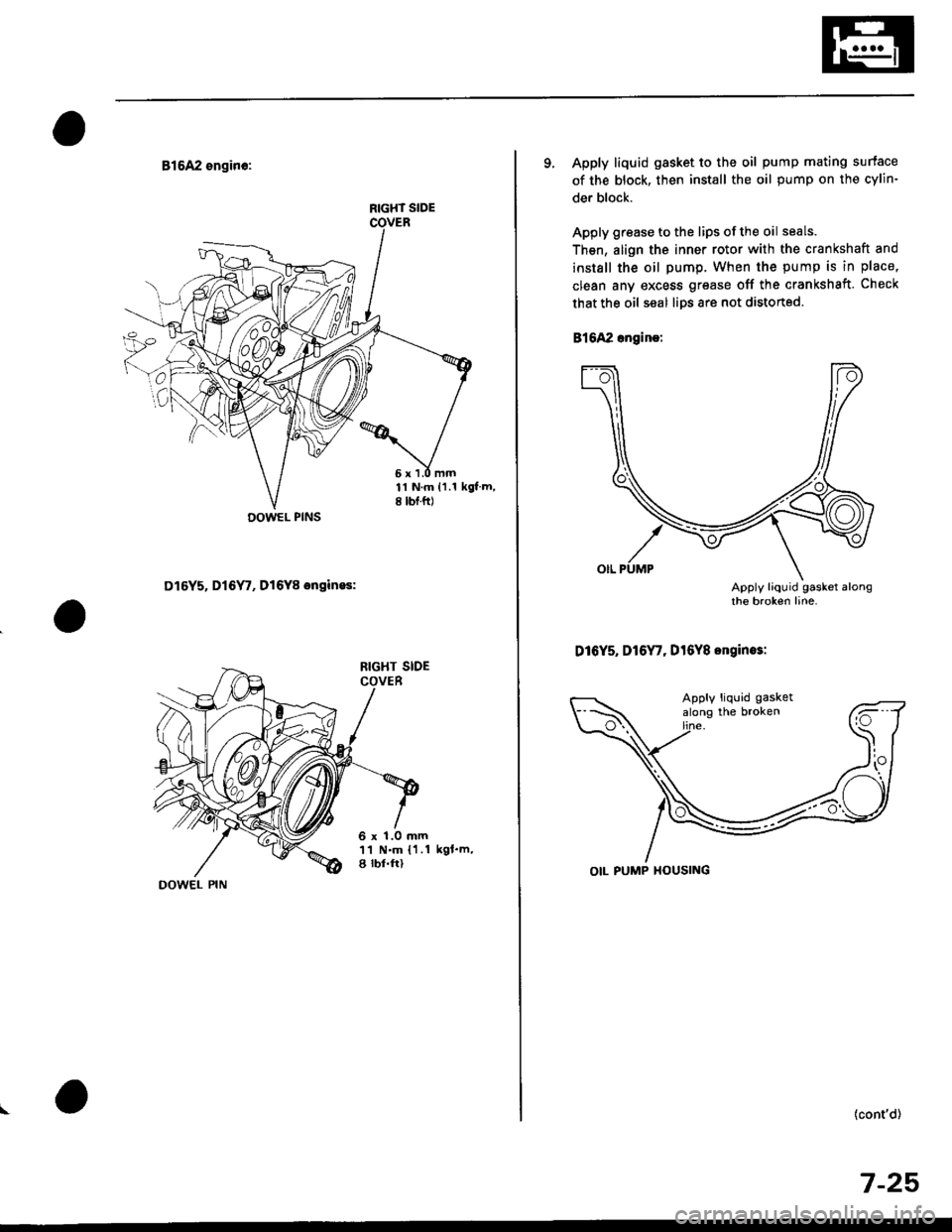
81642 ongin€:
D16Y5, Dl6fr, Dl6Y8 engines:
k9l.m,
RIGHT SIDE
DOWEL PINS
6 x 1.0 mm11 N.m {1.1a rbf.ft)
OOWEL PIN
9. Apply liquid gasket to the oil pump mating surtace
of the block, then install the oil pump on the cylin-
der block.
Apply grease to the lips of the oil seals.
Thgn, align the inner rotor with the crankshaft and
install the oil pump. When the pump is in place,
clean any excess grease off the crankshaft. Check
that the oil seal lips are not distorted.
B16A2 ongino:
Apply liquid gasket alongthe broken line,
Dl6Y5, Dl6Y7, Dt6Y8 ongino3:
Apply liquid gasket
along the broken
OIL PUMP }{OUSING
{cont'd)
7-25
Page 240 of 2189
Oil Pump
RemovaUlnspection/lnstallation (cont'dl
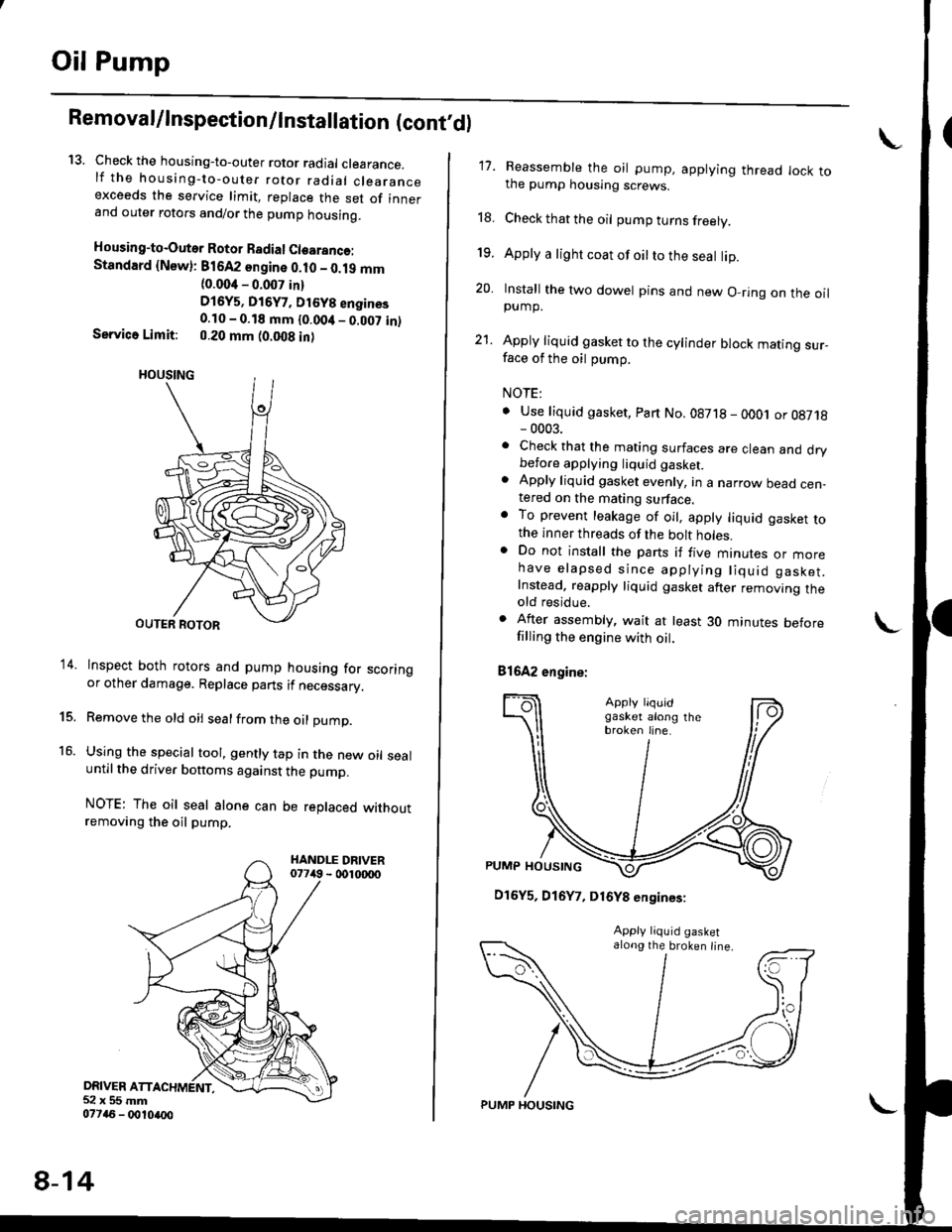
13. Check the housing-to-outer rotor radial clearance.lf the housing-to-outer rotor radial clearanceexceeds the service limit, replace the set of innerand outer rotors and/or the pump housing.
Housing-to-Outer Rotor Badial Clearanco:Standard {Newl: 816A2 sngine 0.10 - 0.19 mm(0.004 - 0.007 in)
D16y5, Di6y7, Dt6y8 engines0.10 - 0.18 mm {0.00it _ 0.007 in)Service Limit: 0.20 mm (0.008 in)
lnspect both rotors and pump housing for scoringor other damage. Replace parts if necessary.
Remove the old oil sealfrom the oil pump.
Using the special tool, gently tap in the new oil sealuntil the driver bottoms against the pump.
NOTE: The oil seal alone can be replaced withoutremoving the oil pump.
DRIVER ATT52x55mm077a6 - 0010ao0
14.
15.
16.
8-14
PUMP HOUSING
17. Reassemble the oil pump, applying thread lock tothe pump housing screws.
18. Check that the oil pump turns freely.
19. Apply a light coat of oilto the seal lip.
20. Install the two dowel pins and new O-ring on the oilpump.
21. Apply liquid gasket to the cylinder block mating sur_face of the oil pump.
NOTE:
. Use liquid gasket, Part No.08718 - oOOj or 08718- 0003.. Check that the mating surfaces are clean and drybefore applying liquid gaskel. Apply liquid gasket evenly, in a narrow bead cen-tered on the mating surface.o To prevent leakage of oil, apply liquid gasket tothe inner threads of the bolt holes.. Do not install the parts if five mtnures or morehave elapsed since applying liquid gasket.Instead. reapply liquid gasket after removing theold residue.
. After assembly, wait at least 30 minutes beforefilling the engine with oil.
81642 engine:
\
D16Y5, D16Y7, D16Y8 engines:
along the broken line.
Page 270 of 2189

!
Fuel and Emrsslons
SoecialToofs .....,...."..,. 11-2
Component Locations
lndex ....................., ......... 11-3
Svstem Description
Vacuum Connections ................,,..,.. ......... 11-12
Electrical Connections ...............,.,.,... ....... 11-29
System Connectors ........,.,.,.......................... 1 1-51
Troubleshooting
Troubleshooting Procedures ................. .. 11-81
Engine Control Module/PowertrainControl Module TerminalAfiangement ....,.,..... 11-88
Diagnostic Trouble Code Chart .................,., 11.97
How to Read Flowcharts .,.......................... . 11-103
PGM-Fl System
System Description ...... 11-10,1
Troubleshooting Flowcharts
Engine Control Module/PowertrainContlol Module ........ 11-107
Manitold Absolute Pressure Sensor .....'. . ... 11-115
fntake Air Temperatuie Sensor ..... . . ., . 11'121
Engine Coolant Temperatuae Sensol ........., 11-128
Throttle Position Sensor ...................,........... 11-132
Primary Heated Orygen Sensor (Sensor 1l ... 11-139
Secondary Heated Oxygen Sensor(Sensor 21.................................................... 1 1-153
Heated Oxygen Sensor Heater ...................,. 11-157
Fuel Supply System ...... 11-164
Random Mislire ......., ..11-166
Misfire Detected in One Cylindsr ................. 11-167
Knock Sensor .,.,............ 11-170
CKP/TDC/CYP Sensor ................................... 11'172
Vehicle Speed Sensor ...........,......,...,.,........... 1t-176
Barometric Pressure Sensor ...............,......... I 1-178
Electrical Load Detector,.,,............................ 1 1-179
CKF Sensor .................... 11-183
ECM/PCM Internal Circuit ............................. I 1-188
A/T Signal {TMA/TMBI .................................. I 1-189
ldle Control System
System Doscriplion ............ 11-190
Troubleshooting Flowcharts
ldle Control System ...... 11-192
ldle Air Control Va1ve .................................... I 1-19i1
Starter Switch Signal .................................... 1 1'202
Air Conditioning Signal ................................. 11'201
Ahernator FR Signal .................................... . 1 1-208
BrakeSwitch Signal ..................................... f 1"210
Power Sleering Prossure Switch Signal ......11-212
A/T Gear Position Signal ............................... 11-216
Clutch Swiich Signal ................................-.... 11-214
ldte Speed Setting . .............11-220
Fuel Supply System
Fuel Lines .,...................,.,.,.,11-221
Fuef Tube/Ouick-Connect Fittings ..........,.,........ 11 -227
System Description ....'.... 11-230
Fuel Pressure .......,.,,........... 11-230
Fuef fniectors ......................11-232
Fu€f Pressure Regulator .....,.......................'...,. 11-231
Fuef Fifter ............................11-235
Fuel Pump .............'.......'.... 11-236
PGM-FI Main Relay .............11'237
Fuel Tank ................ ....,...'.'.' 11'211
Intake Air System
System Description ....-.-.....11-243
Air Cfeaner ...........,......."". .11-211
Throttle Cable .....................11-211
Throttfe Body ........ ..'... . . .,.11-211
Fuel Iniestion Air Control System ,.,.,....-........... 11-250
Emission Control System
System Description .-..........11-252
Taifpip€ Emission ...............11-252
Three Way Catafytic Convert€r ............,.,,.,.,.,.... 11 -252
Exhaust Gas Racirculaiion System ...,.,,,,.,.,.,.,,. 11'254
Positive Crankcas€ Ventilation System .... . . .. 11-266
Evaoorative Emission Controls ..................,,..,.,. 11 -267
Page 320 of 2189
System Connectors [Fuel Pumpl
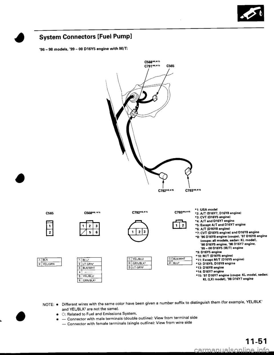
'95 - 98 models, '99 - 00 Dl6Y5 engine with M/T:
ffi
c565
E
c792*r,.'5c793|.,.s
*1r USA mod€l'2: A/T {O16Y7, D16Y8 ensine}13: CVT {O16Y5 ensin€l*4: A/T ind D16Y7 .ngane*5: ExceFt A/T end D16Y7 engine'6: A/T lDl6Y8 enginel*7: CvT (Dl6Y5 enginoland 016Yg engine'8: ,96 Dl6YB engine {coupe),'97 Dl6Y8 sngine
{coupe: sll models, s€d.nr KL modell,'98 Dl5Y5.ngine,'98 D16Y7 engine,'99 - OO Dl6Y5 (M/Tl enginer9: D16Y5 onginet10: M/T {D15Y5 ensinelr1t: ExceDt M/T (D16Y5 engine)tl2: D16Y5, Dl6Yg engine*13: Dl6Y8 enginer14: D16Y7 engine*15:'97 Dl6Y7 ensine {coupe: KL model, sodan:
KL (LX) modeu,'98 Dt6Y7 engine
NOTE: . Different wires with the same color have been given a number suffix to distinguish them (for example' YEUBLK1
and YEVBLK'� are not the samel.
. O: Related to Fuel and Emissions System'
. - Connector with male terminals (dou ble outline): View f rom term inal side
- Connector with female terminals (single outline): View from wire side
c7931...15
ffi
1 1-51
Page 322 of 2189
![HONDA CIVIC 1999 6.G Service Manual Cl0,r{C.nadal
rfr]
l6mrrrnru IElilrwA----llTltHtBtu__l
:lo.
llrl
lrl.l
c109..
rfrtr
16lonl -l
l@LYEUBLK Ibfgl-rcgtu---l
c102
rTrtt
l6lwtr,eED _-l
E|BFIvBLK -l
l6lga-tnEcl--l
c105
Etr
c106
ffi
c HONDA CIVIC 1999 6.G Service Manual Cl0,r{C.nadal
rfr]
l6mrrrnru IElilrwA----llTltHtBtu__l
:lo.
llrl
lrl.l
c109..
rfrtr
16lonl -l
l@LYEUBLK Ibfgl-rcgtu---l
c102
rTrtt
l6lwtr,eED _-l
E|BFIvBLK -l
l6lga-tnEcl--l
c105
Etr
c106
ffi
c](/img/13/6068/w960_6068-321.png)
Cl0,r{C.nadal
r'fr]
l6mrrrnru IElilrwA----llTltHtBtu__l
:lo.
l'lrl
lrl.l
c109..
r'frtr
16lonl -l
l@LYEUBLK' Ibfgl-rcgtu'---l
c102
r'Trtt
l6lwtr,eED' _-l
E|BFIvBLK -l
l6lga-tnEcl--l
c105
Etr
c106
ffi
c114
fr
c108
ffi
c107
ffi
Bffiffi
c113*1
ffiffi
,DGRN/BLK'(9LT GRN?BLU]38
NOTE: . Different wires with the same color have been given a number suffix to distinguish them (for 6xample, YEUBLK1
and YEUBLK'�are not the same).
. O: Related to Fuel and Emissions Syst€m'
. - Connector with male terminals (double outline): View from terminal side
- Connector with female terminals (single outline): View trom wire side
(cont'd)
11-53
c1a2.r
fr