passenger door HONDA CIVIC 1999 6.G Service Manual
[x] Cancel search | Manufacturer: HONDA, Model Year: 1999, Model line: CIVIC, Model: HONDA CIVIC 1999 6.GPages: 2189, PDF Size: 69.39 MB
Page 1704 of 2189

Power Windows
Passenger's Window Motor Test
Front:
1. Remove the passenger's door panel (see section
20t.
2. Disconnect the 2P connsctor from the window
moIor.
2P CONNECTOR
\
Terminal side ot msleterminals
3. Check window motor operation by connecting power
and ground according to the table.
CAUTION: When the motor stops running. dbcon-
nest ono load immadiatoly.
4. lf the motor doas not run or fails to run smoothly.
replace it.
Terminal
;;,r";--lI
UP@o
DOWN@
23-234
Re!r:
1. Remove the passenger's door panel {see section
20).
2. Disconnect the 2P connectof from the window
motor.
NOTE: The illustration shows the right rear window
motor; the left rear window motor is symmetrical.
2P CONNECTOR
3. Check window motor operation by connecting power
and ground according to the table.
GAUTION: Whon the motor ctops running, discon-
nact one lead immodiatoly.
4. lJ the moto. does not run or fails to run smoothly.
rcDlace it,
Terminal
DI;t;;---l
UPo@
DOWN@
Page 1721 of 2189
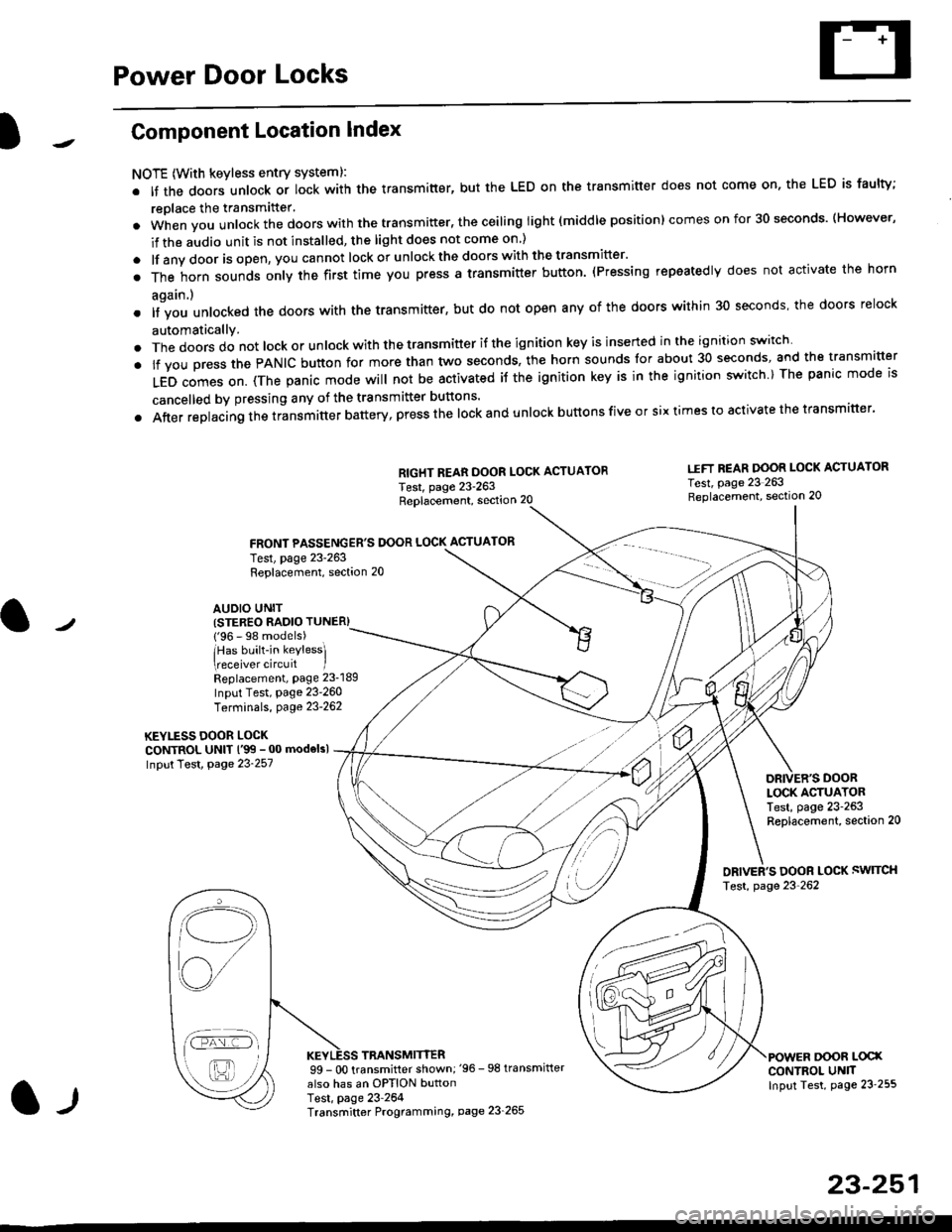
Power Door Locks
Component Location Index
NOTE (With keyless entry systeml:
. It the doors unlock or lock with the transmitter, but the LED on the transmitter does not come on, the LED is faulty;
replace the transmitter'
. when vou unlock the doors with the transmitter, the ceiling light (middle position) comes on for 30 seconds. (However,
if the audio unit is not installed, the light does not come on )
. lf any door is open, you cannot lock or unlockthe doors with the transmitter'
. The horn sounds only the first time you press a transmitter button. (Pressing repeatedly does not activate the horn
again.)
o lf vou unlocked the doors with the transmitter, but do not open any of the doors within 30 seconds, the doors relock
automatically.
. The doors do not lock or unlock with the transmitter if the ignition key is inserted in the ignition switch
. lf you press the PANIC button for more than two seconds, the horn sounds for about 30 seconds, and the transm'fer
LED comes on. (The panic mode will not be activated iJ the ignition key is in the ignition switch ) The panic mode is
cancelled by pressing any of the transmitter buttons'
o After replacing the transmitter battery, press the lock and unlock buttons five or six times to activate the transmitter'
Replacement, section 20
FRONT PASSENGER'S DOOR LOCK ACTUATOR
RIGHT REAR DOOR LOCK ACTUATOR
Test, page 23-263
I.IFT REAR DOOR LOCK ACTUATOR
Test, page 23 263Replacement, section 20
LOCK ACTUATORTest, page 23-263Replacement, section 20
ORIVER'S DOOR LOCK SWITCH
Test, page 23'262
DOOR L@XCONTROL UN]TInput Test, page 23 255
23-251
Test, page 23-263Replacement, section 20
AUDIO UNIT(STER€O RADIO TUNER)
{'96 - 98 models)
lHas built-in keylessl
eceiver circuit IReplacement, page 23-189
Input Test, page 23-260
Terminals, page 23-262
KEYLESS DOOR LOCKCONTROL UNIT l'99 - 00 modelsl
Input Test, Page 23-257
l-l
TRANSMITTER99 - 0O transmitter shown;'96 -98 transmifter
also has an OPTION buttonTest, page 23-264Transmitter Programming, page 23_265
Qi,,a/
/----
L(ru
i'.-8,-'l
/'-'6
Page 1722 of 2189
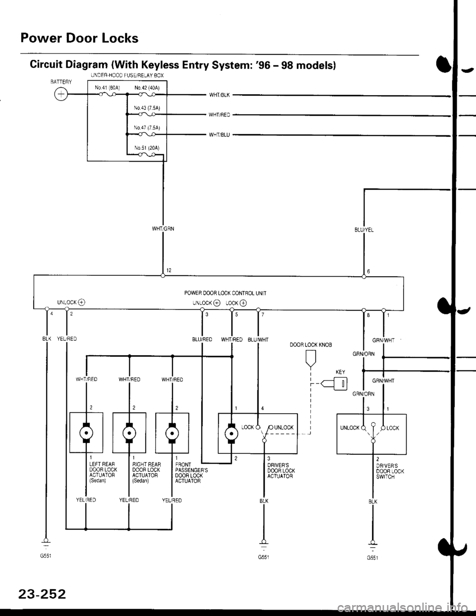
Power Door Locks
Circuit Diagram (With Keyless Entry System: '96 - 98 modelsl
WHTi BLK
WHT/BED
WHT/BLU
LOCK KNOB
n
Y KEY| -----.f--;-)
i-q__!J
8LK
G551
ll,o"., L
I PASSENGER'SI DoOF LOCKI ACTUATOR
IIYEUREO
WHT/RED WHT/FED
l,l,
tA-r rA] r.
qJ_*:[:,,,:
liqi*"""r llqi*'€trYELIRED YELi REDBLK
I
No.4l 180A) N0.42 (40A)
WHT/GRN
UNDER.HOOD FUSEi RELAY BOX
POWER OOOR LOCK CONTROL UN T
uNLocK@ rocK @
t'8LU/REDI'YELTRED
GRNiORN
GRN/]/VHT
BLK
G55l
23-252
Page 1728 of 2189
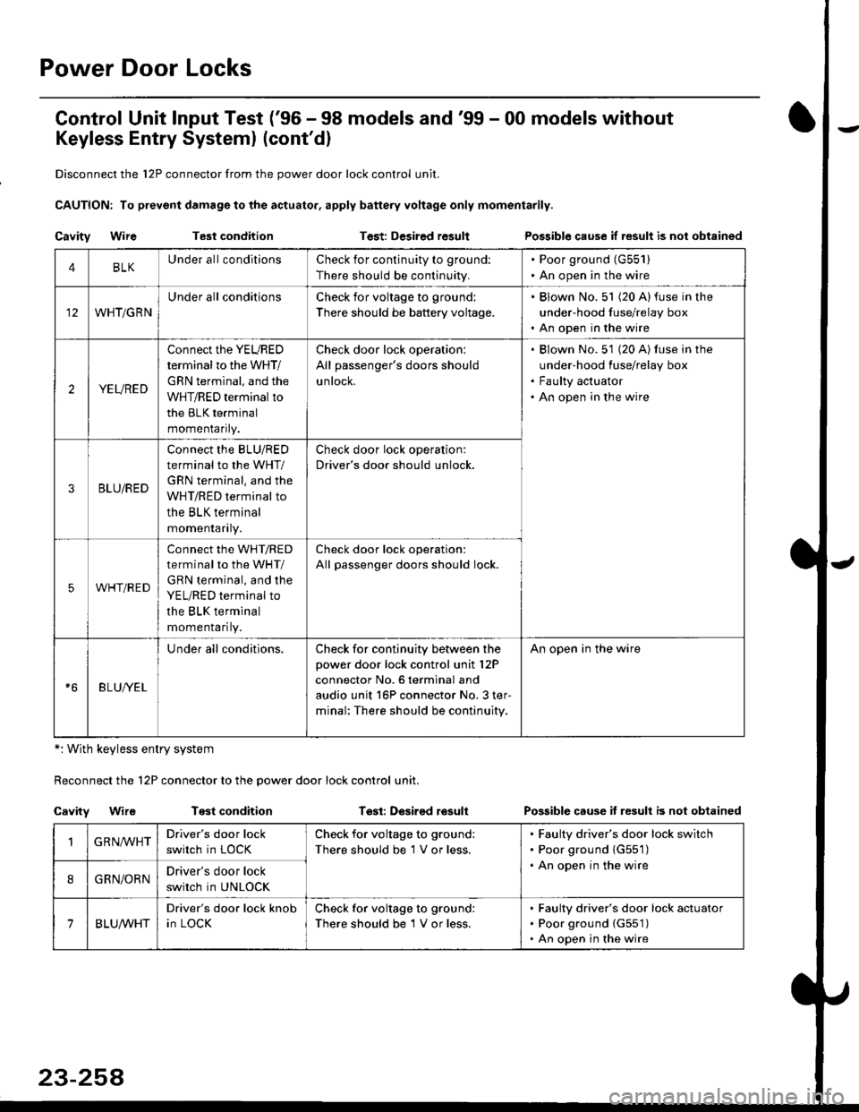
Power Door Locks
Control Unit lnput Test ('96 - 98 models and'99 - 00 models without
Keyless Entry Systeml (cont'dl
Disconnect the 12P connector from the power door lock control unit.
CAUTION: To prevsnt damage to the actuator, apply battery voltage only momentarily.
Cavity WireTest conditionTest: Desired resultPossible cause if result is nol obtained
*: With keyless entry system
Reconnect the 12P connector to the power door lock control unit.
Cavity WireTest conditionTssl: Desirsd losullPossible cause it resull b not obtained
4BLKUnder all conditionsCheck for continuity to ground:
There should be continuity.
. Poor ground (G55'l ). An open in the wire
WHT/GRN
Under all conditionsCheck for voltage to ground:
There should be battery voltage.
. Blown No. 51 (20 A)fuse in the
under-hood fuse/relay box. An open in the wire
2YEURED
Connect the YEURED
terminal to the WHT/
GRN terminal, and the
WHT/RED terminal to
the BLK terminal
momenraflty.
Check door lock operation:
All passenger's doors should
untocK.
Blown No. 51 {20 A) fuse in the
under-hood fuse/relay box
Faulty actuator
An open in the wire
3BLU/RED
Connect the BLU/RED
terminal to the WHT/
GRN terminal. and the
WHT/RED terminal to
the BLK terminal
momenraflry.
Check door lock operation:
Driver's door should unlock.
5WHT/RED
connect the WHT/RED
terminal to the WHT/
GRN terminal, and the
YEL/RED terminal to
the BLK terminal
momenrafl ty.
Check door lock operation:
All passenger doors should lock.
BLU/YEL
Under all conditions.Check for continuity between the
power door lock control unit l2P
connector No. 6 terminal and
audio unit 16P connector No. 3 ter-
minal: The.e should be continuity.
An open in the wire
GRN,ryVHTDriver's door lock
switch in LOCK
Check for voltage to ground:
There should be 1 V or less.
Faulty driver's door lock switch
Poor ground {G551)
An open in the wire
8GRN/ORNDriver's door lock
switch in UNLOCK
7BLUA/VHT
Driver's door lock knob
in LOCK
Check for voltage to ground:
There should be 1 V or less.
Faulty driver's door lock actuator
Poor ground {G551)
An open in the wire
Page 1730 of 2189
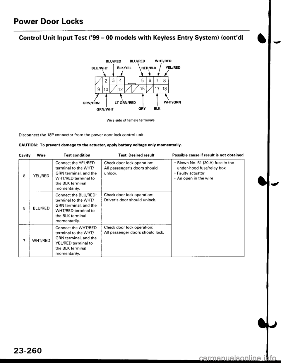
Power Door Locks
Control Unit Input Test ('99 - 00 models with Keyless Entry System) (cont'd)
BLU/RED WHT/RED
8LU/WHT8LK/YELRED/BLK
2345618
91012/t/t517td
LT GRN,/RED
BLK
Wire side of female terminals
Disconnect the 18P connector from the oower door lock control unit.
CAUTION: To prevent damage to the actuator, apply baftery voltage only momentarily.
Cavity WileTest conditionTest: Desired resultPossible cause if result is not obtained
BLU/RED
YEL/RED
WHT/GRN
GRN/WHT
IYEURED
Connect the YEURED
terminal to the WHT/
GRN terminal, and the
WHT/RED terminal to
the BLK terminal
momenraflty,
Check door lock operation:
All passenger's doors should
untocK.
Blown No. 51 (20 A) fuse in the
under-hood fuse/relay box
Faulty actuator
An open in the wire
5BLU/RED
Connect rhe BLU/RED1
terminal to the WHT/
GRN terminal, and the
WHT/RED terminal to
the BLK terminal
momenlaflry_
Check door lock operation:
Driver's door should unlock.
7WHT/RED
Connect the WHT/RED
terminal to the WHT/
GRN terminal, and the
YEURED terminal to
the BLK terminal
momenlaflry.
Check door lock operation:
All passenger doors should lock.
23-260
Page 1735 of 2189
l
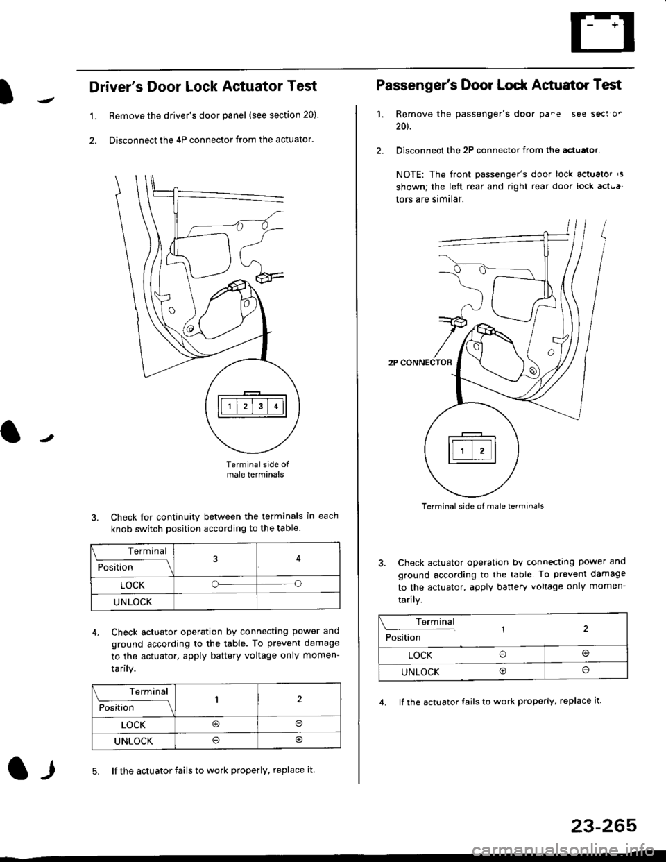
Driver's Door Lock Actuator Test
1. Remove the driver's door panel (see section 20).
2. Disconnect the 4P connector from the actuator.
J
Terminalside ofmale terminals
3. Check for continuity between the terminals in each
knob switch position according to the table.
4. Check actuator operation by connectlng power ano
ground according lo the table. To prevent damage
to the actuator, apply battery voltage only momen-
tarilY.
l-l5. lf the actuator fails to work properly. replace it
23-265
Terminal
F""lti* - lll
LOCKo
UNLOCK
Terminal
Fo"JJ'-lrlon';" -ll1
LOCK@o
UNLOCK
Passenger's Door Lodr Actuator Test
1.
2.
Remove the passenger's doo. pa^e see sect o'
201.
Disconnect the 2P connector from lhq aclualor
NOTE: The front passenger's door lock actualor ,s
shown; the left rear and right rear door lock act{,a
tors are similar.
Terminal side ol male terminals
3. Check actuator operation by conneclrng power and
ground according to the table To prevent damage
to the actuator, apply banery voltage only momen-
tarily.
4. lf the actuator Iails to work properly, replace it.
Terminal,2Position
LOCK O@
UNLOCK Oo
Page 1822 of 2189
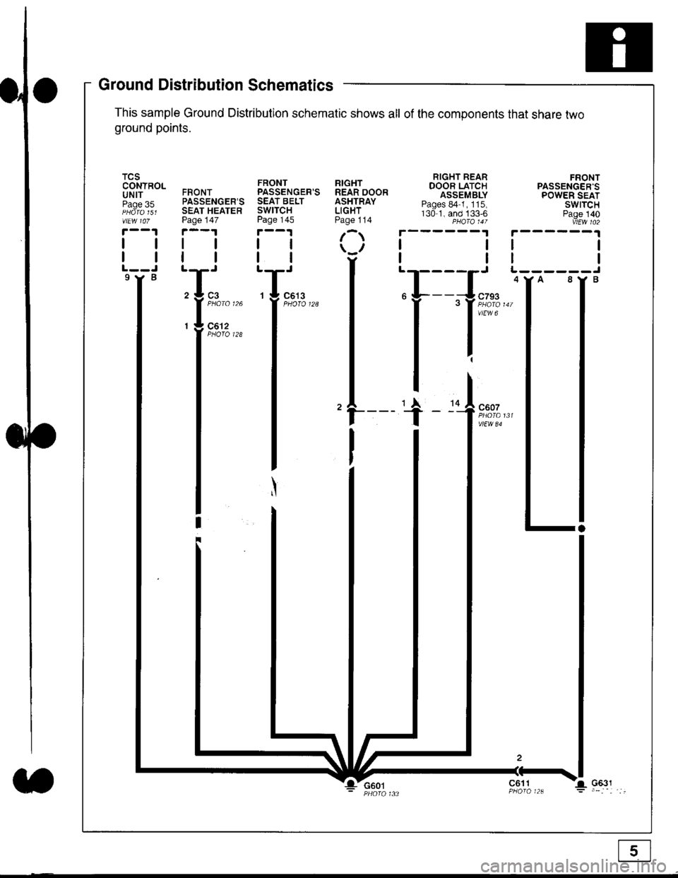
Ground Distribution Schematics
This sample Ground Distribution schematic shows all of the components that share two
ground points.
TCSCONTROLUNITPage 35
tl
tl
9Y B
FRONTPASSENGER'SSEAT HEATERPage 147
tl
FRONTPASSENGER'SSEAT BELTSWITCHPage 145
tl
ll
RIGHTREAR DOORASHTRAYLIGHTPage 114
r
\u
tl'T-'
29 3
l'::'"'^I - Ut
Z
II
I
G601c611
Page 1835 of 2189
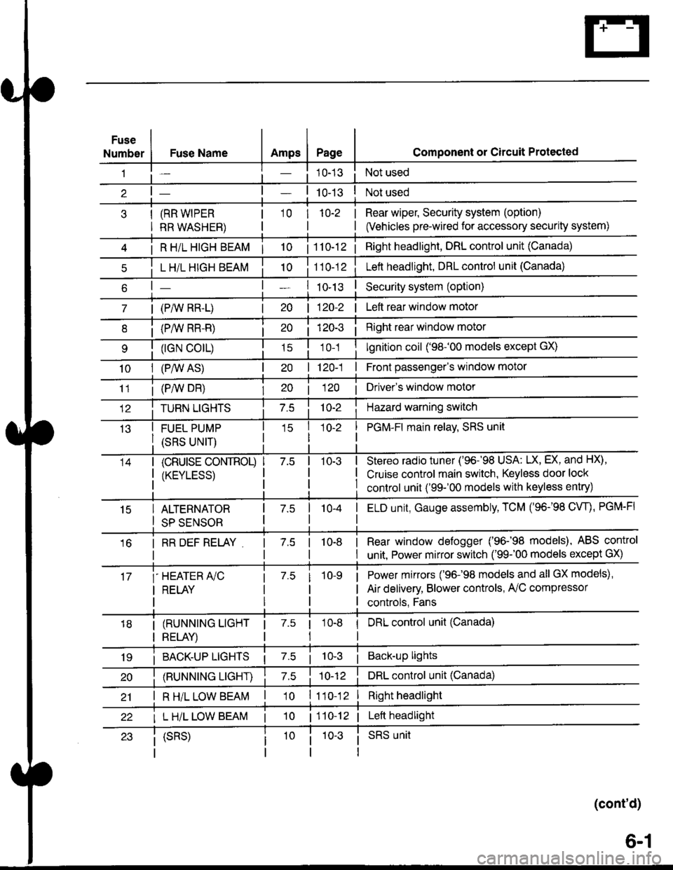
Fuse
NumberAmpsPageFuse Name
(RR WIPER
RR WASHER)
i R HiL HIGH BEAM | 10
L H/L HIGH BEAM
| (PAIV RR-L)
i (P/vv RR-R)
(rGN CO|L)
10I (P,^/V AS)
Component or Circuit Protected
Not used
Not used
Rear wiper, Security system (option)
(Vehicles pre-wired for accessory security system)
'10r 1n-2
I
| 1 10-12i Right headlight, DRL control unit (Canada)
Lett headlight, DRL control unit (Canada)
I ro-rsSecurity system (option)
| 120-2 | Left rear window motor
Right rear window motor
lgnition coil ('98-'00 models except GX)
| 120-1 | Front passenger's window motor
i (PiW DH)| 20 1 12O I Driver's window motor
TURN LIGHTSHazard warning switch
FUEL PUMP
(SRS UNIT)
PGM-FI main relav, SRS unit
(cRUrsE CoNTROL)
/KtrVt trSS\
Stereo radio tuner ('96-'98 USA: LX, EX, and HX),
Cruise control main switch, Keyless door lock
control unit ('99-'00 models with keyless entry)
15ALTERNATOR
SP SENSOR
l-a10-4I ELD unit, Gauge assembly, TCM (96-'98 CW, PGM-FI
16I RR DEF RELAY7.510-8I Rear window defogger ('96-'98 models), ABS control
I unit. Power mirror switch ('99-'00 models except GX)
i-HEATER r/C
I RELAY
Power mirrors ('96-98 models and all GX models),
Air delivery, Blower controls, AilC compressor
controls, Fans
I (RUNNING LIGHT
I RELAY)
1 7.5 1
tl
I DRL control unit (Canada)
i BACK-UP LTGHTSi Back-up lights
(RUNNING LIGHT)DRL control unit (Canada)
I R H/L LOW BEAM'10 l11o-12Right headlight
I L H/L LOW BEAM | 101110-12 | Left headlight
(cont'd)
(SRS)SRS unit
6-1
Page 2014 of 2189
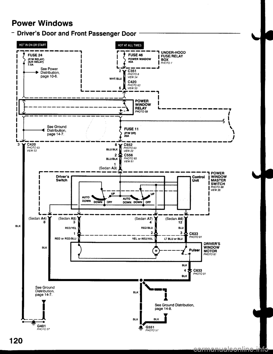
Power Windows
- Driver's Door and Front Passenger Door
FUSE 24
{s/n nElav)
Se€ PowefDistribution,page 106.
l' l-'G'-.i
- -
I i',I3.',8J39"
i ) lo1*" **oo*
i f,?T" ,
L-9------J'rF,*%,
*rtier-u |
'ry'
6I i[ff'3"
PowER !wtNDow IRELAYPHOfO 6S
see GroundDistribution,page 14-7.
I
I
I\
\
I
D ver'5SwitchContrslUnlt
POWERwtNDowMASTERswtTcrlPHATO 88vlEw 36
I
I
I
(Sedan A4)8(Sedan A5)
REO/^YEL
1
FED or aEO/BLU
(Sedan A7)4
RED/BLU
(Sedan A6)12
ALU
c633
YEL o. REo/YELLT BLU oT BLU
DRIVER'SwlNDowMOTOR
BLK
4
ALK
c633
See GroundDistribution,page 14-7.
I
I
I
See Ground Distibution,page 14€.
.---+<- G401PHOIA 57
0
c42O I Y C552
ii,?;?,* "., ".* ! f[fflo,u,
2 e C556".,,".* | f[ff11r,1 (Sedan A3) l
12
G551
Page 2018 of 2189
Power Windows (contd)
- How the Circuit Works
CAUTION: You could iniure your arms, hands, or
fingers if you unintentionally switch the driver's
window to "automatic down" while working in
that door with the power on. Disconnect the
window switch conneclot or the battery when
working in the driver's door.
System Description
The operation of the power windows is controlled by
the main switch in the power window master switch.
When the main switch is in OFF, only the driver's door
window can be opened or closed. With the main
switch ON, all windows can be ooened or closed
either by swtches in the master panel, or swttches in
the doors. The driver's window switch also has an
automatic down mode which is tumed on by pushing
the switch down to its second oosition.
The power windows are driven by reversible motors.
Each motor is protect€d by a built-in circuit breaker.
lf the window switch is held on too long (with the
window obstructed, or after the window is fully up or
down), the circuit breaker opens the circuit. The
circuit breaker resets automaticallv as it cools.
Driver's Window
With the ignition switch in ON, voltage is provided to
the coil of the power window relay through fus€ 24.
The contacts of the power window relay close, and
voltage is applied to the driver's switch. When you
push the power window master switch to UP, voltage
is applied to the driver's window motor. (The motor's
ground path is back through the master power
window switch.) The driver's window motor then
drives the window up. When you push the switch to
DOWN, voltage is applied in the opposite direction
and the motor drives the window down.
Automatic Down (Driver's Window)
With the ignition switch in ON or START, voltage is
applied to the coil of the power window relay. The
contacts of the power window relay close and
voltage is applied lo the power window master
switch. When you push the driveas switch to the
AUTO DOWN position, voltage is applied through
the driver's switch to the driver's window motor. The
control unit receives pulses at the pulser input while
the motor is running. When the window is fully
down, the motor stops, and pulses are no longer
generated by the pulser. This is sensed by the
control unit at the pulser input, and voltage is no
longer applied to the driver's window motor.
Passenger Windows
With the ignition switch in ON, voltage is applied to
the coil of the power window relay through fuse 24.
The contacts of the power window relay then close,
applying voltage to the individual window switches
and the power window master switch. With the
master panel main switch ON, the passenger
windows can be ooerated from the individual
window switches or from tho master panel switches.
When you push the front passengsr's window
switch to UP, voltage is applied to the f ront
passenger's window motor. (The motor is grounded
through the contacts in the front passenger's
window switch and the oower window master
switch.) The window moves up as long as you hold
the switch in the UP position. lf you push the switch
to DOWN, voltage is applied in th€ opposite
direction to the front passenger's window motor, and
the window movss down as long as you hold the
switch in the DOWN Dosition. The window switches
in the other doors operate similarly.
When you push the front passenger's switch in the
master panel to UP, voltage is applied through the
front passenger's window switch contacts to the
front passengefs window motor. (The motor is
grounded through the contacts in the front
passenger's window switch and the power window
master switch.) The window moves up as long as
you hold the switch in the UP position. lf you push
the switch to DOWN, voltage is applied in the
opposite direction to lhe front passenger's window
motor, and the window moves down as long as you
hold the switch in the DOWN position. The other
passenger window switches in the master panel
operate similarly.
Refer to the Service Manual (Section 23, Electrical)
for specific tests or troubleshooting procedures.
120-4