piston ring HONDA CIVIC 1999 6.G Repair Manual
[x] Cancel search | Manufacturer: HONDA, Model Year: 1999, Model line: CIVIC, Model: HONDA CIVIC 1999 6.GPages: 2189, PDF Size: 69.39 MB
Page 1112 of 2189
Steering Gearbox
Reassembly (cont'd)
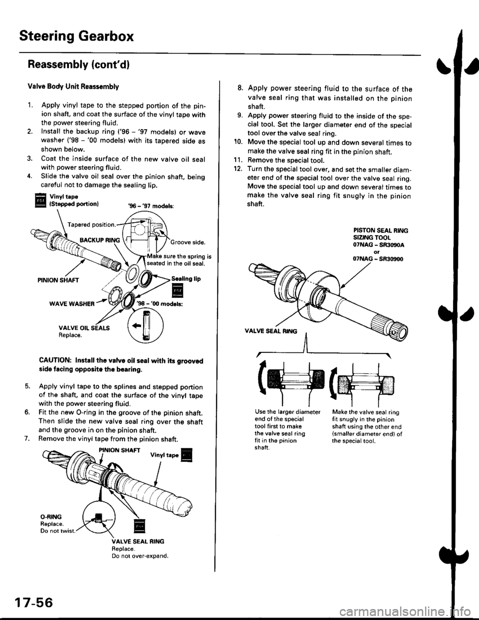
Valve Body Unit Reassembly
1. Apply vinyl tape to the stepped portion of the pin-
ion shaft, and coat the surface of the vinyl taoe with
the power steering fluid.
2. Install the backup ring ('96 -'97 models) or wavewasher ('98 -'00 models) with its tapered side as
shown below.
3. Coat the inside surface of the new valve oil sealwith power steering fluid.
4. Slide the valve oil seal over the pinion shaft, being
careful not to damage the sealing lip.
Vinyl t.po{Stepped ponion}
Tap6red position.
BACKUPGroove side.
sure the spring isseatod in the oil seal.
'98 - '00 mod.b:
CAUTION: InstEll ihe valve oil seal whh its groov.d
3ide tacing opposite tho boaring.
Apply vinyl tape to the splines and stepped portion
of the shaft, and coat the surface of the vinyl tapewith the power steering fluid.
Fit the new O-ring in the groove of the pinion shaft.Then slide the new valve seal ring over the shaft
and the groove in on the pinion shaft.
Remove the vinyl tape from the pinion shaft,
'96 - '97 models:
lip
7.
VALVE SEAL RIiIGReplace.Do not over-expand.
17-56
8. Apply power steering fluid to the surface of the
valve seal ring that was installed on the pinion
shaft.
9. Apply power steering fluid to the inside of the spe-cial tool. Set the larger diameter end of the specialtool over the valve seal ring.
10. Move the special tool up and down several times tomake the valve seal ring fit in the pinion shaft.11, Remove the soecial tool.
12. Turn the special tool over, and set the smaller diam-eter end of the special tool over the valve seal ring.Move the special tool up and down several times tomake the valve seal ring fit snugly in the pinion
shaft.
PISTON SEAL BINGSIZING TOOL07NAG - SR:togoAol07NAG - SR3|X)00
(g(m
Use the larger diameterend of the specialtool first to makethe valve seal ringfit in the pinionshaft.
Make the valve seal ringfit snugly in the pinionshaft using the other end(smaller diameter end) ofthe specialtool.
Page 1115 of 2189
)
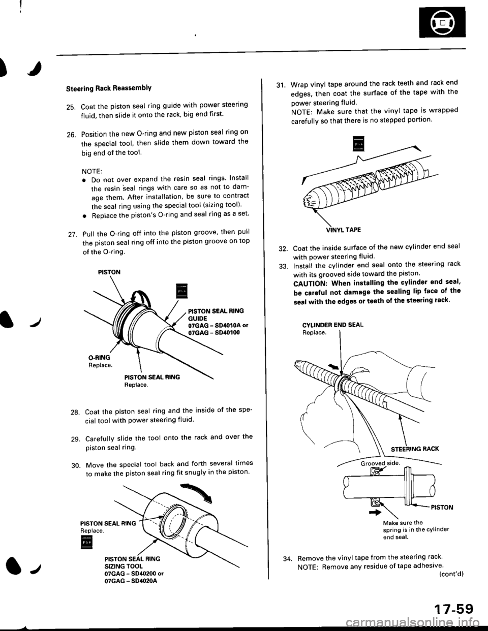
Steering Rack Reassembly
25. Coat the piston seal ring guide with power steering
fluid, then slide it onto the rack, big end first'
26. Position the new O-ring and new piston seal rlng on
the special tool, then slide them down toward the
big end of the tool
NOTE:
. Do not over expand the resin seal rings lnstali
the resin ;eal rings with care so as not to dam-
age them. After installation, be sure to contract
the seal ring using the specialtool (sizing tool)
. Replace the piston's O-ring and seal ring as a set'
27. Pull the O-ring off into the piston groove, then pull
the piston seal ring off into the piston groove on top
ol the O-ring
PISTON SEAL RINGGUIDE07GAG - SD4O10A ol
07GAG - SD,ol(xt
Coat the piston seal ring and the inside of the spe-
cial toolwith power steering fluid.
Carefully slide the tool onto the rack and over the
piston seal ring.
Move the special tool back and forth several times
to make the piston seal ring fit snugly in the piston'
PISTONReplace.
E
PISTON
31. Wrap vinyl tape around the rack teeth and rack end
edges, then coat the surface of the tape with the
power steering fluid
NOTE: Make sure that the vinyl tape is wrapped
carefully so that there is no stepped portion
Coat the inside surface of the new cylinder end seal
with power steering fluid.
Install the cylinder end seal onto the steering rack
with its grooved side toward the piston.
CAUTION: When installing the cylinder end seal,
be caieful not damage the sealing lip face of tho
seal with the edgss or teeth of th€ ste€ring rack'
CYLINDER END SEAL
Make sure thesPring is in the cylinder
end soal
Remove the vinyl tape from the steering rack
NOTE: Remove any residue oftape adhesive(cont'dl
17-59
Page 1116 of 2189
Steering Gearbox
Reassembly {cont'd)
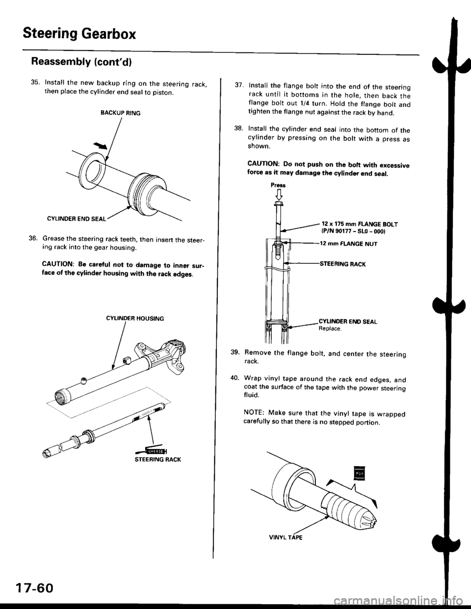
35. Install the new backup ring on the steering rack,then place the cylinder end seal to piston.
Grease the steering rack teeth, then Insen the steer-ing .ack into the gear housing.
CAUTION: Be careful not to damage to inner sur-face of the cylindsr housing with the rack edges.
36.
BACKUP RING
17-60
37. Install the flange bolt into the end of the steerinorack until it bottoms in the hole, then back thlflange bolt out 1/4 turn. Hold the flange bolt andtighten the flange nut against the rack by hand.
38. Install the cylinder end seal into the bottom of thecylinder by pressing on the bolt with a press asshown.
CAUTION: Do not push on the boh with excessiveforce as it may damage tho cylinder end seal.
12 x 175 mm FLANGE BOLT{P/N 90177 - SLo - 000}
12 mm FLANGE NUT
?qRemove the flange bolt. and center the steeringrack.
Wrap vinyl tape around the rack end edges. andcoat the surface of the tape with the power steeringfluid.
NOTE: Make sure that the vinyl tape rs wrappedcarefully so that there is no stepped portion.
Preas
Page 1117 of 2189
)
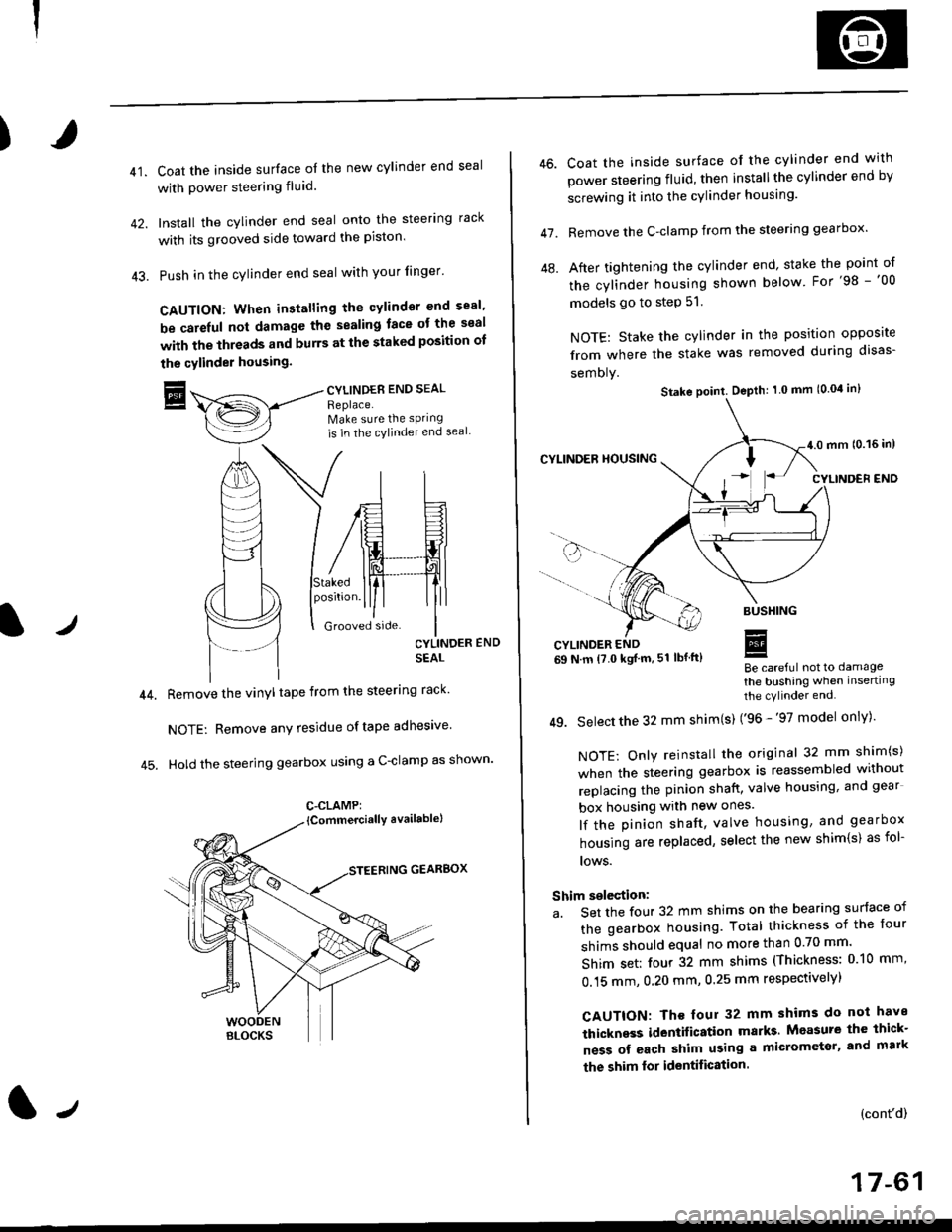
41.Coat the inside surface of the new cylinder end seal
with power steering fluid.
Install the cylinder end seal onto the steering rack
with its grooved side toward the piston'
Push in the cylinder end seal with your finger'
CAUTION: When installing the cylinder end sesl'
be carelul not damage the sealing face ot the seal
with the threads and burrs at the staked position oI
the cylinder housing.
trCYLINDES END SEAL
Replace.Make sure the sPring
is in the cylincler end seal
CYLINDER END
SEAL
Remove the vinyl tape from the steering rack'
NOTE: Remove any residue oftape adhesive
Hold the steering gearbox using a C-clamp as shown'
GEARBOX
C-CLAMP:
l-,
46.
47.
Coat the inside surface of the cylinder end with
power steering fluid, then installthe cylinder end by
screwing it into the cylinder housang.
Remove the C-clamp from the steering gearbox'
After tightening the cylinder end' stake the point of
the cylinder housing shown below For'98 -'00
models go to step 51.
NOTE: Stake the cylinder in the position opposite
from where the stake was removed during disas-
semoly.
Be careful not to damage
the bushing when inserting
the cylinder end.
49. Select the 32 mm shim(s) ('96 -'97 model only)'
NOTE: Only reinstall the original 32 mm shim(s)
when the steering gearbox is reassembled without
replacing the pinion shatt, valve housing, and gear
box housing with new ones.
lf the pinion shaft, valve housing, and gearbox
housing are replaced, select the new shim{s) as fol-
lows.
Shim selection:
a. Set the four 32 mm shims on the bearing surface of
the gearbox housing. Total thickness of the four
shims should equal no more than 0 70 mm'
Shim set: four 32 mm shims (Thickness: 010 mm'
0.15 mm, 0.20 mm, 0.25 mm respectivelyl
CAUTION: Th€ four 32 mm shims do not have
thickness identification marks Measure the thick-
ness of each shim using a micrometsr, and mark
the shim lor identification.
(cont'd)
17-61
Stake point. Depth: 1 0 mm (0.04 in)
Page 1167 of 2189
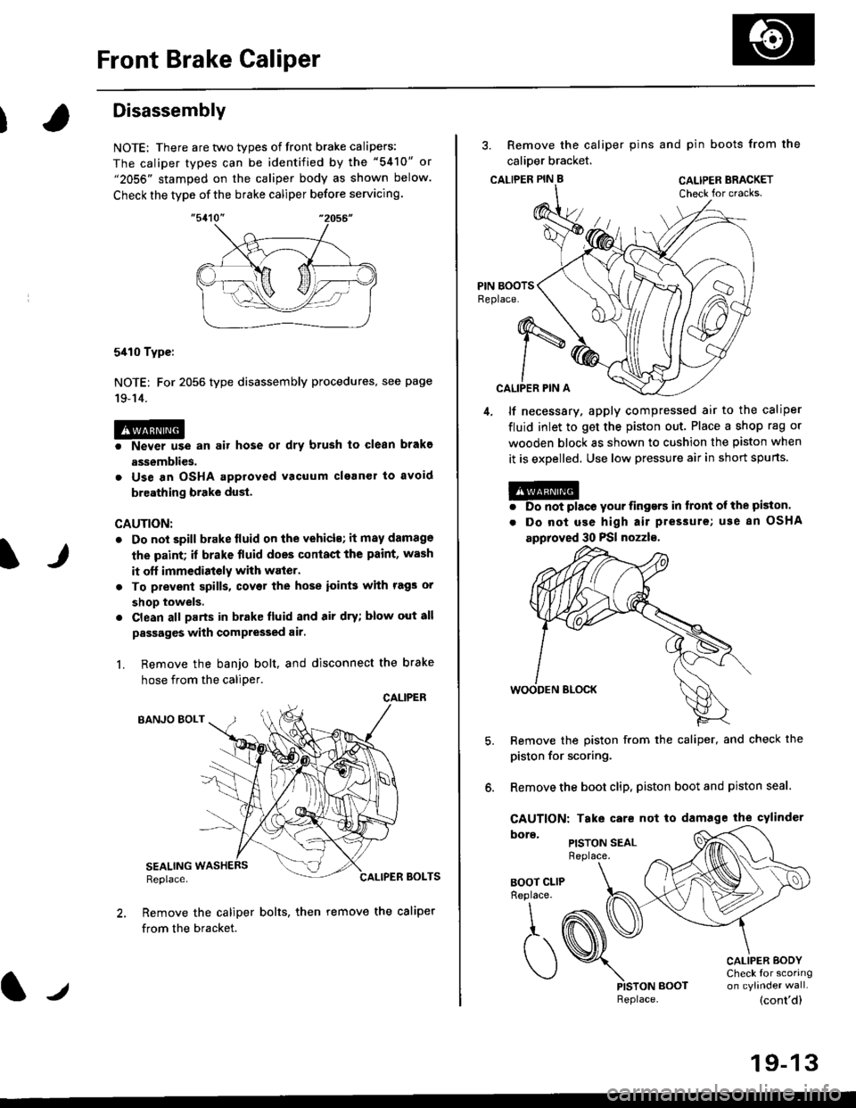
Front Brake Caliper
It
Disassembly
NOTE: There are two types of front brake calipers:
The caliper types can be identified by the "5410" or"2056" stamped on the caliper body as shown below.
Check the type of the brake caliper before servicing.
5410 Type:
NOTE: For 2056 type disassembly procedures, see page
19-14.
@o Never use an air hose ot dry brush to clean brakg
assemblies.
. Use an OSHA approved vacuum clganer to avoid
breathing brake dust.
CAUTION:
. Do not spill brake lluid on the vehicls; it may damage
the paint; if brake fluid does conlact the paint, wash
it off immedistely with waier.
. To prevenl spills, covet the hose ioin$ with rags or
shop towels.
. Clean all parts in brake fluid and air dry; blow out all
passages with compressed air.
L Remove the banjo bolt, and disconnect the brake
hose from the caliDer.
CALIPER
BANJO EOLT
SEALINGReplace.BOLTS
Remove the caliper bolts, then remove the caliper
from the bracket.
lJReplace.
3. Remove the caliper pins and pin boots from the
calioer bracket,
CALTPER PIN B CAL|PER BRACKET
CALIPER PIN A
4, lf necessary. apply compressed air to the caliper
fluid inlet to get the piston out. Place a shop rag or
wooden block as shown to cushion the piston when
it is expelled. Use low pressure air in short spurts.
@. Do not place your iingers in tront ol the piston.
. Do not use high air pressure; use 8n OSHA
approved 30 PSI nozzls,
Remove the piston from the caliper, and check the
piston for scoring.
Remove the boot clip, piston boot and piston seal.
CAUTION: Take care not to damage the cylindcr
PISTON SEALReplace.
BOOT CLIPReplace.
\,
,t. (
)PISTON BOOT
CALIPER BODYCheck for scoring
(cont'd)
19-13
Page 1168 of 2189
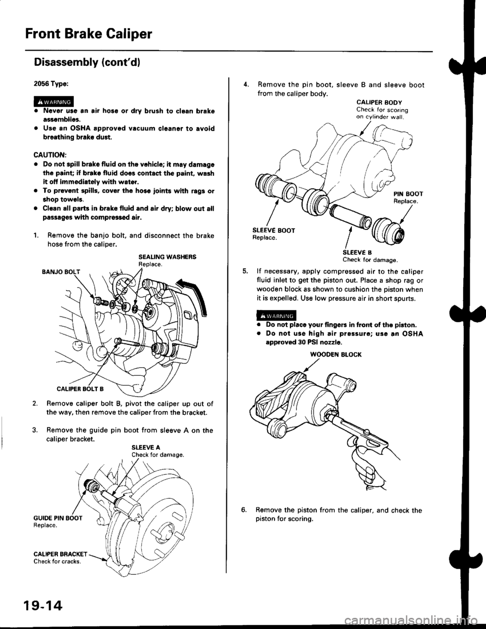
Front Brake Caliper
2056 Type:
@
Disassembly (cont'dl
Nevor u3e an air hos€ or dry brush to clgan brake
assomblios.
Use an OSHA approved vacuum cl6aner to avoid
braathing braks duet.
CAUTION:
. Do not spill brakefluid on ths vchicle; it may damage
the paint; if brako fluid does contact the p.int. wash
it olt immediately with wato..
. To prevsnt spills, cover the ho3o ioints whh rag3 or
shop towels.
. Cl€an all parts in brake fluid and air dry; blow out 8ll
passagss with compr63€d air.
1. Remove the banjo bolt, and disconnect the brake
hose from the caliper.
SEALING WASHERS
Remove caliper bolt B, pivot the caliper up out of
the way, then remove the caliper from the bracket.
Remove the guide pin boot from sleeve A on the
caliDer bracket.
GUIDE PIN BOOTReplace.
GALIPER BRACKETCheck tor cracks.
Check for damage.
19-14
4. Remove the pin boot, sleeve B and sleeve boot
from the caliper body.
CALIPER EODYCheck for scoringon cytinder wa .
SLEEV€ BCheck for damage.
lf necessary, apply compressed air to the csliper
fluid inlet to get the piston out. Place a shop rag or
wooden block as shown to cushion the oiston when
it is expelled. Use low pressure air in short spurts,
a
a
Do not placo your lingers in ftont ol tho pkton.
Do noi usa high air prsssure; uso an OSHA
approved 30 PSI nozzle.
Remove the piston from the caliper, and check thepiston for scoring.
WOODEN ALOCK
Page 1182 of 2189
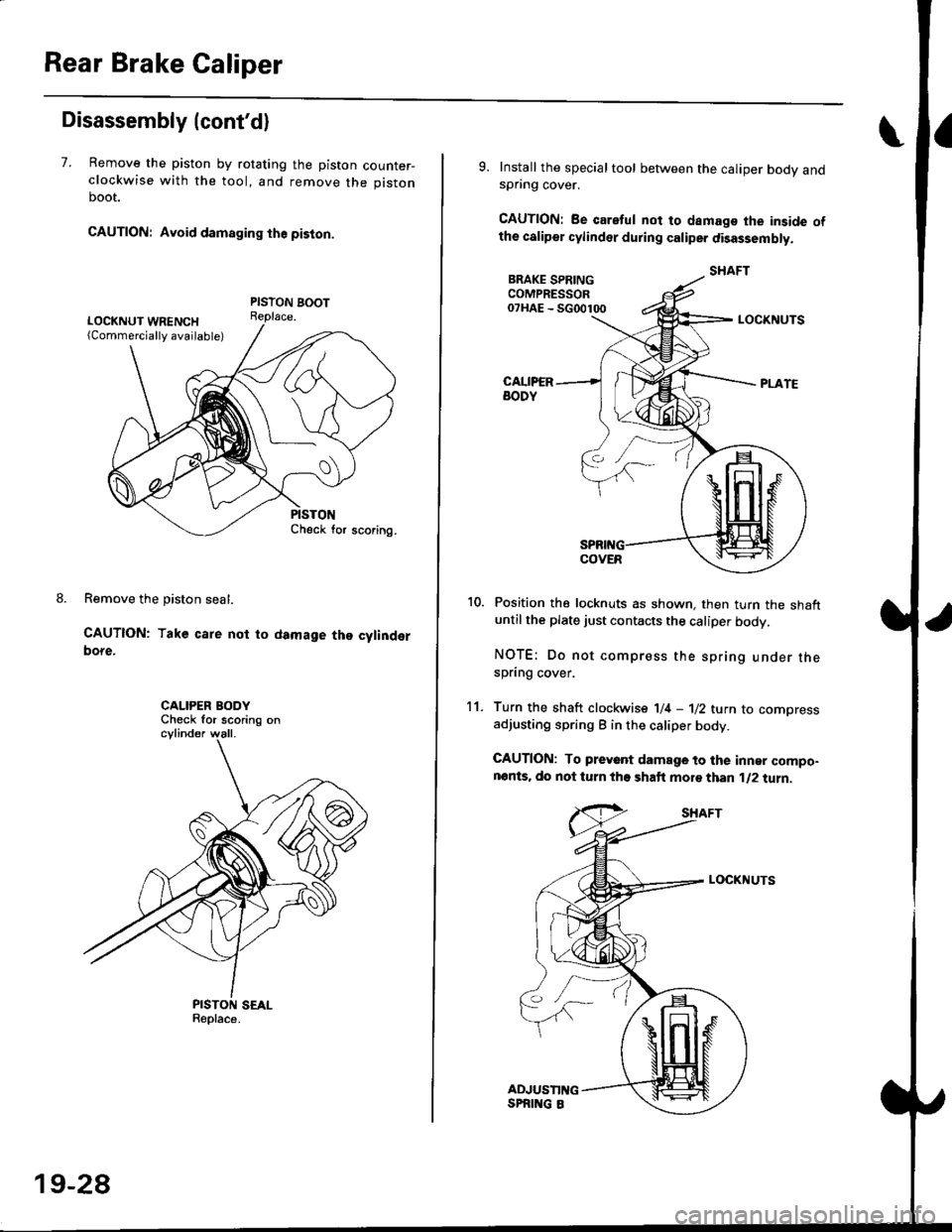
Rear Brake Galiper
Disassembly (cont'd)
7. Remove the piston by rotating the piston counter-clockwise with the tool, and remove the piston
boot.
CAUTION: Avoid damaging the piston.
PISTON BOOTReplace.
Remove the piston seal.
CAUTION: Take care not to damage the cylinderbore.
CALIPER BODYCheck for scoring on
9. Install the special tool between the caliper bodv andspnng cover.
CAUTION: Be caretul not to damags the inside ofthe caliper cylinder during caliper disassembty.
BRAKE SPRINGCOMPRESSOR07HAE - SG00100
11.
LOCKNUTS
Position the locknuts as shown. then turn the shaftuntil the plate just contacts the caliper body.
NOTE: Do not compress the spring under thespring cover.
Turn the shaft clockwise 1/4 -'ll2 tu.n to comoressadjusting spring B in the caliper body.
CAUTION: To preyant damage to the inner compo-nonts. do not turn the shaft mor€ than 1/2 turn.
SHAFT
LOCKNUTS
PISTON SEALReplace.
ADJUSTII{GSPRING 8
19-28
Page 1183 of 2189
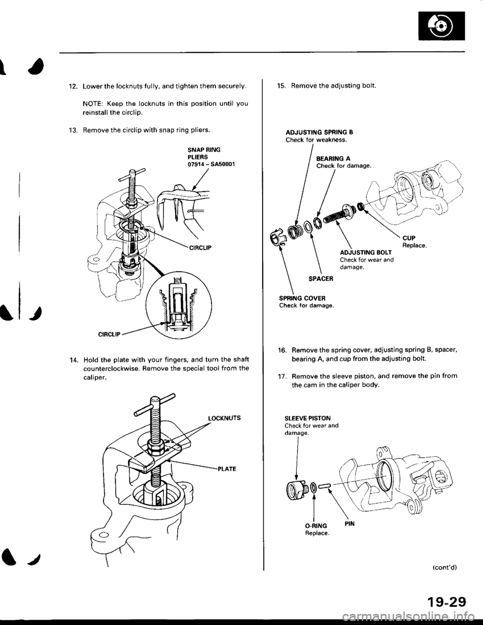
\
13.
Lower the locknuts fully, and tighten them securely.
NOTE: Keep the locknuts in this position until you
reinstallthe circlip.
Remove the circlip with snap ring pliers.
SNAP RINGPLIERS07914 - SA50001
't 4.Hold the plate with your fingers, and turn the shaft
counterclockwise. Remove the special tool from the
calioer.
LOCKNUTS
l./
15. Remove the adjusting bolt.
Remove the spring cover, adjusting spring B, spacer,
bearing A, and cup from the adjusting bolt.
Remove the sleeve piston, and remove the pin from
the cam in the caliper body.
'17 .
SLEEVE PISTONCheck lor wear anddamage,
i
I
I
6-50-awl \
IO-RIITGRepl6ce.
(cont'd)
19-29
Page 1185 of 2189
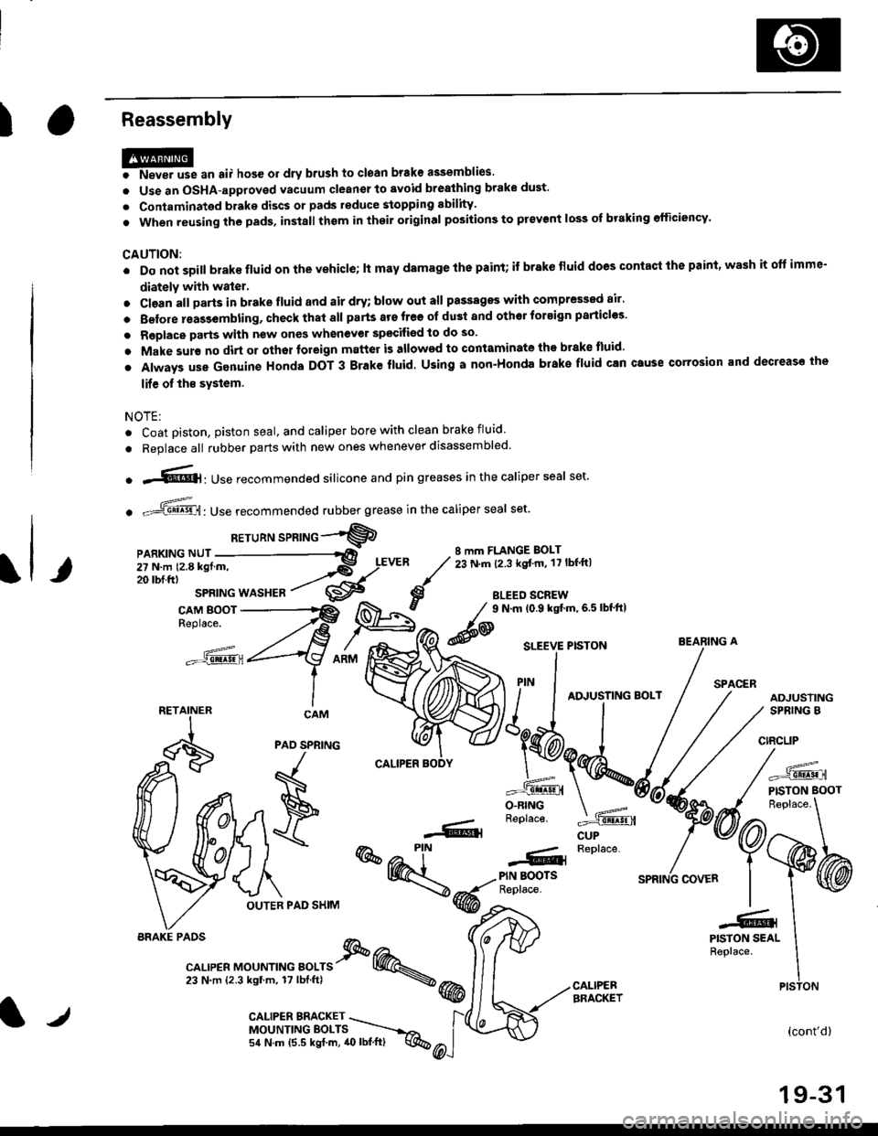
IReassembly
HP* "n ",, hos6 or drv brush to ctoan brake assemblies.
o Use an OSHA-approved vacuum cleanel to avoid brealhing brake dust'
. Contaminated brake discs or pads reduce stopping sbility.
. When reusing the pads, in3tall thom in thoil original positions to prevent loss of braking efficiency'
CAUTION:
. Do not soill brake fluid on the vehicle; lt may damage lhe paint; if brake fluid does contacl the paint' wash it oft imme-
diately with water.
. Cl€an all Darts in brake fluid and air dry; blow out all passagss with comPressed air'
. Belore rsas3embling, check that all parts ars free ot du3t and othor tor€ign particles'
. Replace parts with new ones whenever spscifiod to do so.
o Make sur€ no dirt or othor foreign matter is allowed to contaminate the brake tluid'
. Always use Genuine Honda DOT 3 Brake fluid. Using a non-Honda brake fluid can Gtuse corrosion and decrease the
lif€ of ths system.
NOTE:
. Coat piston, piston seal, and caliper bore with clean brake fluid
. Replace all rubber parts with new ones whenever disassembled.
o .-'{@]: Use recommended silicone and pin greases in the caliper seal set.
. -ffi,Use recommended rubber grease in the caliper seal set.
RETuRN sPRTNG -"'9
8 mm FLANGE BOLT23 N.m (2.3 kgt'm, 17 lbf ftl
BLEED SCREW
@
9 N.m (0.9 kgtm,6.5lbf'ft|
CUP
=^.
PISTON BOOT
(cont'd)
19-31
BEARING A
PAO SPNING
F
\
OUTER PAD SHIM
r--- Replace..ffiPIN BOOTSReplace.
-61
@@-t-.
"l-r,r., "or"'*o " orr" I @.,23 N.m {2.3 kgtm, 17lbf.ftl \@
PISTON SEALReplace.
CALIPEBBRACKET
iiilji:ll;;
__X.,,..".^
BRAKE PAOS
PISTON
l/CALIPER BMCKET \MOUNTINGEOLTS ----.-,o,
54 N.m (5.5 kgf.m, 40lbl.ft) q%
Page 1186 of 2189
Rear Brake Caliper
Reassembly (cont'dl
L
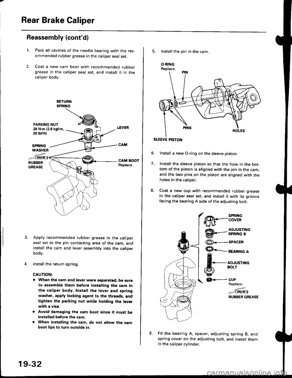
PARKING NUT28 N.m (2.8 kgt m,20 rbr.trt
Pack all cavities of the needle bearing with the rec,
ommended rubber grease in the caliper seal set,
Coat a new cam boot with recommended rubbergrease in the caliper seal set, and install it in thecaliper body.
SPRII{GWASHEN
z..-_e!!!9!.{RUBBERGREASE
Apply recommended rubber grease in the caliperseal set to the pin contacting area of the cam, andinstall the cam and lever assembly into the caliperbodv.
lnstall the return spring.
CAUTION:
. When the cam and lever wgre separatod. b€ surgto assemble them bofore installing the cam inthe caliper body, Install the lev€r and spring
washer. apply locking agent to the threads, andtighten the parking nut while holding the l.vorwhh a vise,
. Avoid damaging the cam boot since it must bsinstalled before thg cam.. When installing the cam, do nol allow the camboot lips lo turn outside in.
19-32
5. Installthe pin in the cam.
O.RINGReplace.
SLEEVE PISTON
Install a new O-ring on the sleeve pisron.
Install the sleeve piston so that the hole in the bot-tom of the piston is aligned with the pin in the cam,and the two pins on the piston are aligned with theholes in the calioer.
Coat a new cup with recommended rubber grease
in the caliper seal set, and install it with its groove
facing the bearing A side of the adjusting bolt.
7.
€8.--:BTif
@'-.-3nfi""'i"
@--seacrn
$ eeenrne a
fi,*,*^"
GF-
Fit the bearing A, spacer. adjusting spring B, andspring cover on the adjusting bolt, and install themin the caliDer cvlinder.
CUPReplace.
=^.#-g!!!!!Jl
RUBBER GREASE
o