10-2 HONDA CIVIC 1999 6.G Workshop Manual
[x] Cancel search | Manufacturer: HONDA, Model Year: 1999, Model line: CIVIC, Model: HONDA CIVIC 1999 6.GPages: 2189, PDF Size: 69.39 MB
Page 256 of 2189
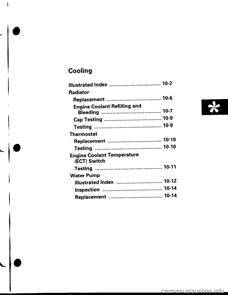
Cooling
fllustrated Index ."..."... ""' 10-2
Radiator
Replacement .'....'...."..."
Engine Coolant Refilling and
Bleeding
Cap Testing
Testing
Thermostat
Replacement .............'....
Testing
10-6
10-7
10-9
10-9
10-10
10-10
Engine Goolant TemPerature
(ECT) Switch
Testing """ 10-11
Water PumP
fffustrated Index ......'... " 10-12
Inspection ' 10'14
Replacement ..'..'...."...'.'....'..'.....'.""" 10-14
!
Page 257 of 2189
lllustrated Index
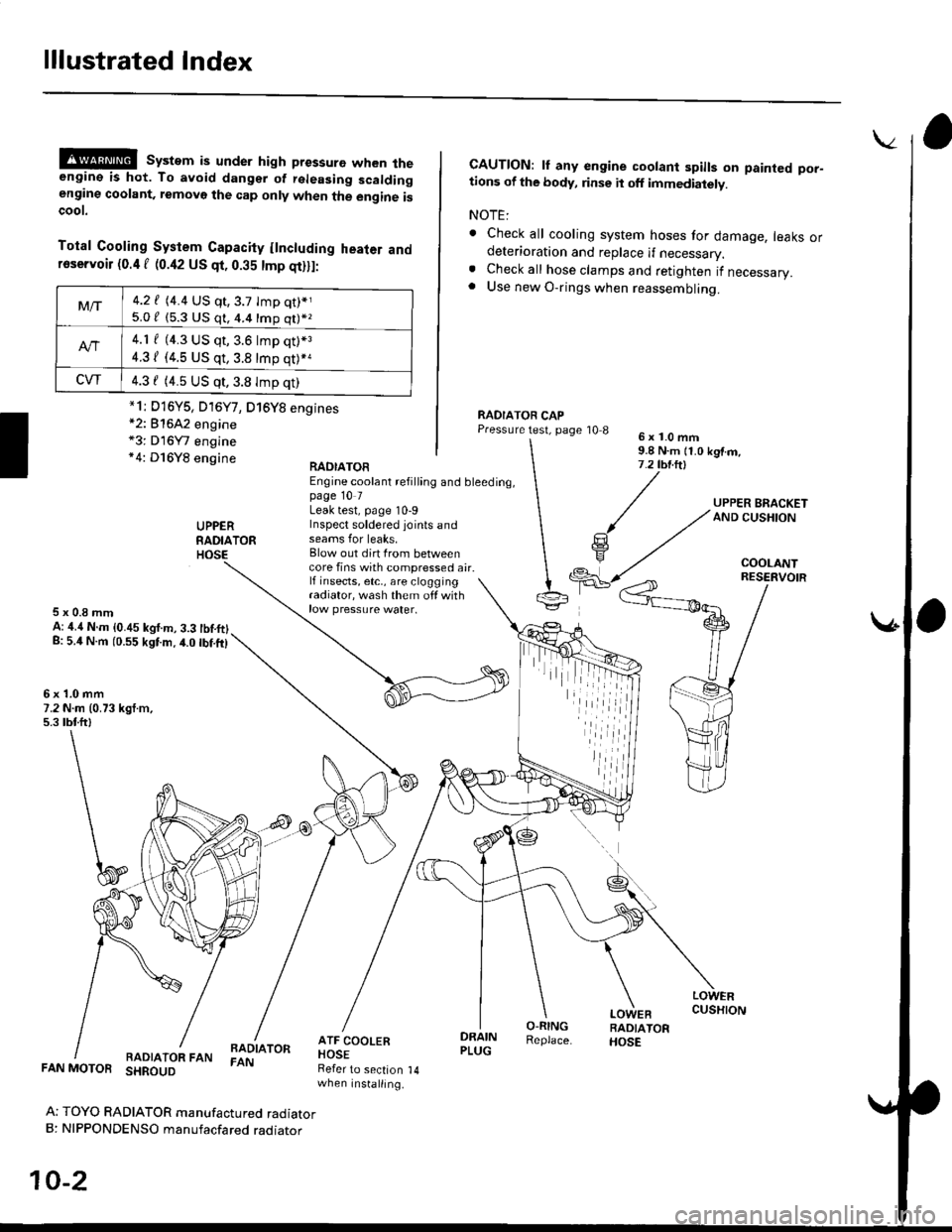
@@ system is under high pressure when theengine is hot. To avoid dangsr of rsleasing scaldingengine coolant, removo the cap only when the engine iscoot.
Total Cooling System Capacity flncluding heater andfoservoir (0.4 f (0.42 US qt, 0.35 tmp qt)ll:
*2: 81642 engine*3: D16Y7 engine*4: D16Y8 engine
CAUTION: lf any engine coolant spills on painted por-tions of the body, rinse it off immediately.
NOTE:
. Check all cooling system hoses for damage, leaks ordeterioration and replace if necessary.. Check all hose clamps and retighten if necessary.. Use new O-rings when reassembling.
RADIATOR CAPPressure test, page '10 86x1.0mm9.8 N.m {1.0 kgtm,7.2 tbt.ltl
UPPERRADIATORHOSE
UPPER BRACKETAND CUSHION
COOLANT
RAOIATOREngine coolant refilling and bleeding,page 10 7Leak test, page 10-9Inspect soldered joints andseams for leaks,Blow out dirt Irom betweencore fins with compressed air.lf insects, etc,, are cloggingradiator, wash them off withrow pressure water.
RESERVOIR
5x0.8mmA: ,1.4 N.m {0.45 kgf.m, 3.3 tbtftlg: 5.4 N.m (0.55 kgtm.4.0 tbf.ft)
6x1.0mm7.2 N.m (0.73 kgt.m,5.3 tbtftl
LOWERCUSHION
RADIATOR FANBADIATORFAN
DRAINPLUG
O-RINGReplace.
LOWEBRADIATORHOSE
FAN MOTOR SHROUD
Ar TOYO RADIATOR manufactured radiatorB: NIPPONDENSO manufacfared raoraror
10-2
Refer to section 14when installing.
Mt-|-4.2 f (4.4 US qt,3.7 tmp qt)*j
5.0 / (5.3 U$ q1, 4.4 16p q11*z
4.1 f (4.3 US qt, 3.6 lmp q0*3
4.31 (4.5 US qt, 3.8 tmp qt)*a
CVT4.3 f (4.5 US qt,3.8 Imp qt)
*1i D16Y5, D16Y7, D16Y8 engines
iil
Page 1205 of 2189
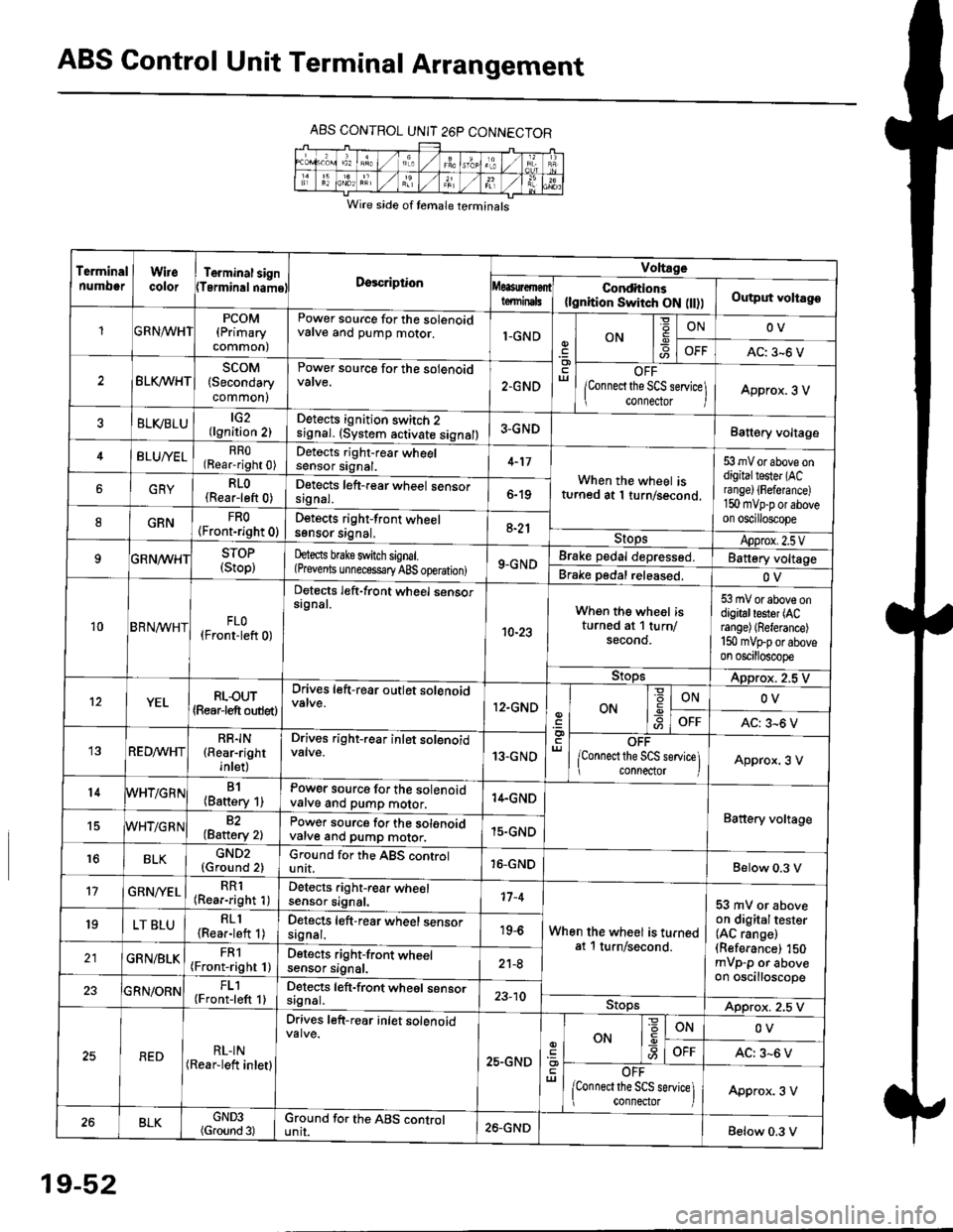
ABS Control Unit Terminal Arrangement
ABS CONTROL UNIT 26P CONNECTOR
Wire side of temale terminals
Terminalnumo0rWirecolorTerminal signTerminalnamoDgscriptionVoltage
Conditions(lgnition Switch ON flt))Output voltagoteminals
PCOM(Primary
common)
Power source for the solenoidvalve and pump motor.1-GNDON
=ONOV
AC: 3-6 V
BLK/WHTscoM(Secondary
common)
Power source for the solenoid
2.GNDOFF
lConnect the SCS service\
conneclor lApprox. 3 V
ELVBLUtG2(lgnition 2)Detects ignition switch 2
!9nal. (system activate signal)3-GNDBatt€ry voltage
BLU/YELRRO(Rear-right 0)Detects right-rear wheelsensor signal.4-17
When the wheel isturned at 1 turn/second.
53 mV or above ondigitaltester (ACra nge) {Fefera nce)150 mvp-p or aboveon oscilloscope
6GRYRLO(Rear-left 0)Detects left-rear wheel sensorsrgnal.6-19
8GRNFRO(Front-right 0)D€tects right-front wheelsgnsor srgnal,a-21StopsApprox.2.5VSTOP(Stop)hects brake switch signal.(Prevents unnecess€ry ABS operation)9-GNDBrake pedal depressed.Battery voltage
Brake pedal released.OV
10BRN^/vHTFLO(Front-left 0)
Detects left-front wheel sensorsignal.
10-23
When the wheel isturned at 1 turn/secono.
53 mV or above ondigitaltester (ACrange) (Referance)
150 mVFporaboveon oscilloscope
9!opsApprox. 2.5 V
12YELRLOUT(Rearjeft outlet)
Drives left-rear outlet solenoid
12.GNDON-9ONOV
OFFAC: 3^6 V
REDMHTRR]N(Rear-right
inlet)
Drives right-rear inlet solenoidvalve.13-GNDOFF
lconnect the SCS service]i connector IApprox. 3 V
14B1(Battery 1)Power source for the solenoidvatve and pump motor.14.GND
Battery voltage15WHT/G R N82(Baftery 2)Power source for the solenoidvarve ano pump motor.15.GND
r6BLKGND2{Ground 2)Ground for the ABS controlunit.16-GNDBelow 0.3 V
17GRN/'/ELRR1(Rear-right 1)Detects right-rear wheelsensor signal.17-4
When the wheel is turnedat 1 turn/second.
53 mV or aboveon digitaltester(AC range)(Referance) 150mVp-p or aboveon oscilloscope
19LT BLURLl(Rea.-left 1)Detects left-rear wheel sensorsagnal.19-6
GRN/BLKFRl(Front-right 1)Detects right-front wheelsensor signal.21-8
FL1(Front-left 1)Detects left-front wheel sensorsignal.23-10StopsApprox. 2.5 V
REDRL-IN(Rear-lett inletl
Drives left-r€ar inlet solenoid
25.GND
ut
ON
'6
-9ONOV
OFFAC: 3-6 V
OFF
lconnect the SCS service] connector lApprox. 3 V
BLKGND3(Ground 3)Ground for the ABS cgntrolunit.26.GNDBelow 0.3 V
19-52
Page 1817 of 2189

Contents
How to Use This Manual ICircuit Schematics (see Circuit Index)Fuse/Relaylnformation 6Ground-to-Componentslndex 6-6ComponentLocationPhotooraohs 201Conriector Views 202
Circuit Index
Accessory power socket 155Air conditionerAir delivery'96198 models 61'99-'00 models 61-2Blower controls'96198 models 60'99100 models 60-1Compressor controls 62Fans 63Anti-lock brake system (ABS) 44A/T gear position indicatorCVT 89All except CVT 89-1Automatic transmission controlsAll '96-'98 models except CVT and GX 39All '99100 models except CVT 39-8All GX models 39-8'96-'�98 CVT 39-4'99100 cw 39-12Back-up lightsCoupe and Sedan 110Hatchback l'10-1Brake lightsAll Coupes and'96-'98 Sedans 110-15'99-'00 Sedans 110-16Hatchback 110-17Brake system indicator light'96198 models 7'1'99100 models 71-1Ceiling light 114-3Charging system 22Condenser fan 63Console lights 114Cruise control 34Dash lights 114Daytime running lights 110- 13Engine coolant temperature gauge 81-1Fog lights 110-10Front parking lights 110-2Fuel gauge 81-1Fuse/relay boxUnder-dash 6Under-hood 6-4Underhood ABS 6-3Gauges 81Ground distribution 14Ground-to-Componentslndex 6-6Hazard warning lightsAll except '99100 Sedans 110-6'99100 Sedans 110-8Headlights 110-12Headlight switch 100Heater - See Air ConditionerHorn'96197 models 40'98 model 40-1'99100 models 40-2lgnition key reminder 73lgnition systemAll '96198 models except Dl685 20All '99100 models except D16Y5 with Mn 2O-2All D1685 engines 20-2'99-'00 D 16Y5 with M/T 20
lndicators 80Integrated control unit 70lnterlock systemAll except'96J98 CVT 138'96198CVT 138-1License plate lightsAll Coupes and '96-'98 Sedans I l0-3'99100 Sedans 1 10-4Hatchback 110-5Low fuel indicator light 74Moonrool'96197 models |22'98-'00 models 122-1Odometer 81Oil pressure indicator light 80-3Power distributionBattery to ignition switch, fuses, and relaysFuses to relays and components 10-2Power door locksAll models without keyless entry 130'96-'98 models with keyless entry 130-2'99100 models with keyless entry 130-12Power mirrorsWithout detogger 141With defogger '141-2
Power windows 120Programmed fuel injection system (PGNr-Fl)All '96-98 models except D1685 23All '99-'00 models except D16Y5with M/T and D1685 24All D1685 engines 25'99100 D16Y5 with M/T 23Radiator fan 63Rear window defogger'96-,98 models 64'99100 models 64-1Seat belt reminder 73Security system'96.'98 USA HX, LX, EX 133'96-'98 Canada EX, Si 133'99TOO USA HX, LX, EX, DX.V Si 133-4'99100 Canada EX, Si 133-4All CX and DX models 133-8Speedometer 81Starting systemA./T (All except Dl685) 21A"/r (D16Bs) 21-1Manualtransmission 21-2Slereo sound system 150Supplemental rastraint system (SRS) 47Tachometer 81TailliqhtsAllboupes and'96-'98 Sedans 110-3'99100 Sedans 1 10-4Hatchback 110-5Trunk light 114-3Turn signal lightsAll except'99100 Sedans 110-6'99-'00 Sedans 1 10-8Vehicle speed sensor (VSS) 33Wiper/washerFront 91Rear 92
10
Page 1820 of 2189
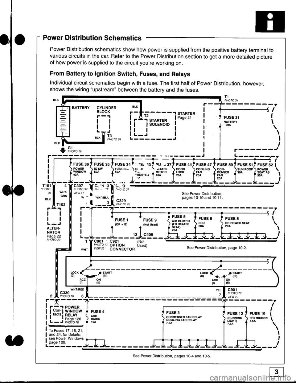
Power Distribution Schematics
Power Distribution schematics show how power is supplied from the positive battery terminal to
various circuits in the car. Refer to the Power Distribution section to get a more detailed picture
of how power is supplied to the circuit you're working on.
From Battery to lgnition Switch, Fuses, and Relays
Individual circuit schematics begin with a fuse. The first half of Power Distribution, however,
shows the wiring "upstream" between the battery and the fuses.
CYLINDERBLOCK
tl
tlL.lt J
",-* f ]fo,o
i BATTERY
IIII
-
----------------Y-?-
ruse so I ruse as I ruse ga | ' ,s. ,a I =u. - srl ruse aai ruse qr I ruse so I ruse sr i ruse iapowEF csw FUsE Bc, \F,.n .;,cren ooon \coounc cor,r. \sun noor powrnw'NDowf50a {* .i1-;.*"1liT""fi3f* f5# fffi'*"f'* fS?'*
- - -L - - -. ... Ji - -.J.- - - -e- - -l. - - -La - J- - - I - - -
"";%,, Y rtr,' .9 l' -%,t",,vtEw47 I ! See Power Dastribution,w - vH-,alr. lt - pages 10,10and 10-11.
' I ---il 9,1?-l--4F--?-
i I
t.urr, 'rrr.,
t i!?'.,,?"" t::=. l ty::.1----.-
-
i
a I r(op-B) .{Noru3€d) J$ifl#ii Jtocl }3fo**."".o'
t -L - - -L - - -: rJ:e'- - -Ei s+s-r -.Fl-J-Jrr.-.
It-STARTER | !Pase 21 ! t FUSE 31I "rn*i
I f
*
i.Jr;-t
i L_i***'" iL-------J
ilr------!
FUSE /I4 ' FUSE 47 ' FUSE 5{' ' FUSE 51' FUSE 52
rlr
OOOB \COOLING CON. \SUN BOOF FOWER
t3f* f5# fffi*" f'* fs?'*
See Power Dastribution,pages 10'10 and 10-11.
T101
34
ALK
4
GAN
I
I
I
I
I\
\I
I
I
FUSE 8DF POWEF SEAT204
FUSE 6ECU204
FUSE 5A/C CLUICH(FN HEATEDSEAD204
C901 C921 {NotPHoro zz OPTION Used)v/EW22 CONNECTOBSee Power Distnbution, page 10-2.
1
FUSE 4
FADIO104
c901
vlEw22
FUSE 12(BUltNrrGLIGHT)
FUSE 19R/C MIRROF
YEL
7
i-f,r-- 't PowERI uon- I Wlt{DOWi racrs i RELAY. t P^da 1tL-J P;dr1ii-
FUSE 3CONOENSEF FAN RELAYCOOLING FAN RELAY
To Fuses 17, 18, 21,and 24, for details,see Power Windowspage 120.a
ll
ll
ALTER-NATORPage 22
f102
c330
See Power Distribution, pages 10-4 and 10-5.
Page 1843 of 2189
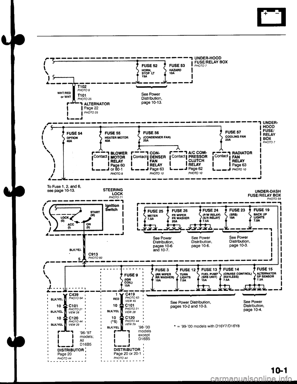
I
t
I
UNDER-HOODFUSE/RELAY BOXFUSE 52HO3 ,9IO? LTt3a
FUSE 53SATAAD10A
T102PHOTO 9l--
S€e PowerDistrib$ion,page 10-13.
WHT/REDT101PI1oIO 25
I
IJ
I
I
FUSEofiro{{oa
ALTEBNATORPage 22
nI
I
t
--1 UNDER.
sFUSE 55IIEATER MOTONatla
r^-::r BLowER| t,omacl I MoToR
i lF5:ftL--J or 50-1Ptaofo9
FUSE 55(co{DEtsER fAx}204
FUSE 57cooutag FAr204
r^-::I RADIATOR
l*"*!F*x.L--J paoro p
HOODFUSE/NELAYBOX
UNDER-DASHFUSE/RELAY BOXPHO|O 58
FUSE 19AACK UPLlalni75A
FUS€ 15ALIIFI.IATORsF sErson7.5A
\
I
I
If
r--1 coN- r--11'/C COM-lContactt DENSER I Contactl PFESSOR
i i[f*, i iFLug"L--J Page 63 L--J Page 62
To Fus€ l, 2, and 6,see oaos lGl3. STEERINGLOCK
\
l,ut-a--- ---------J
gLXTYEI
FUSE 23(sRs)1(rA
Phofo 10
See PowerDistribdion,pagos 10€and 10-7.
FUSE 3tm w|PEain wAsr{ER}10A
PHOTO 10
See PowerDistribution,page 10-6.
FUSE 24(P,ry AEUn(s/n QELAY)
FUSE 13FU€L PUIIP(sns uRrT)15A
See PowerDisaibution,page 10-3.
FUSE 14{cFrrsE corrtRoL}{rcYLESS)
c913I
I
FUSE9 ,
FUSE 12IURI{UCHTS7,trA
) | , i ]si"ii:-' r|r::::---'--- J/--_-r
i::{;iil i i".ii.l ,#,;:|'-
i-:'ff1tu;.,,, i *=ft;;***
See Powsr Distribution,pages 10-2 and 10-3.
* = '99-'00 models with D16Y7/D16YB
Sea PowerDistribuiion,page 10-4.
:! iii'^': i i lB1%"f;
i L-=r -','lo' i !.---i..-^- ii orsrnrauron i i DtsrRtBUroR :' Page 20 Page 20 or 20'1 '
%[-#
I pHOfO 44 PHO|O 44
1Gl
Page 1844 of 2189
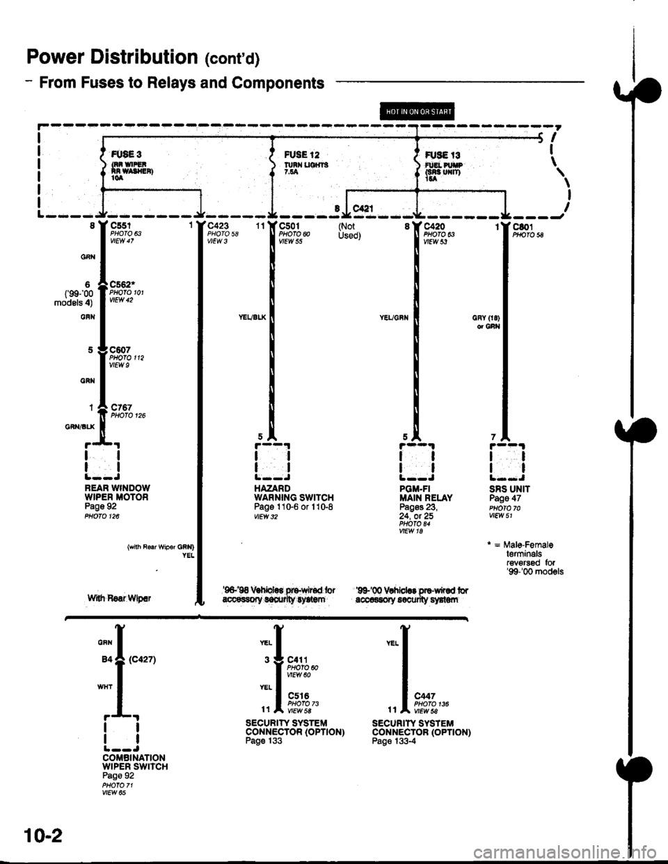
Power Distributiofl (cont'd)
- From Fuses to Relays and Components
R8€3
5A
tl
tl
PGM.FIMAIN RELAYPag$ 23,24, ot 25PHOfO U
GRY (r8)or Cnl|
Gi Ul|�T
llfllvrtl|€n)
FUSE ,'2
nnx ucms7.ta
I
\
\
I
I
c801PHO|O 5Ac423 r'lPHOTO 58c501PHO|O @vtEw 55
tl
ll
HAZARDWAFNING SWITCHPage 110-6 or 110-8vlEw 32
tt
tl
SRS UNITPags 47PUO|O 70vtt:w 51
r = MaleFemalelerminalsrevgrsed for'99-'00 models
onh no'l Wipsr GRN)
w8r Boar Wipif
'9&'00 Vlhbl.. at?wM frrdocarssy 66ourily eldcn
@
rtYELI *. 1'f
ft?'},' I
l,l m*a" ,,l*i*-
SECURITYSYSTEi' SECURIW SYSTEM
F"ontnlSSto"tott'on' S"ontnl5S]ottott'onr
Gnx I
WHT I
r---l
ll
tl
COMBINATIONWIPER SWITCHPage 92
vlEw 05
10-2
Page 1861 of 2189
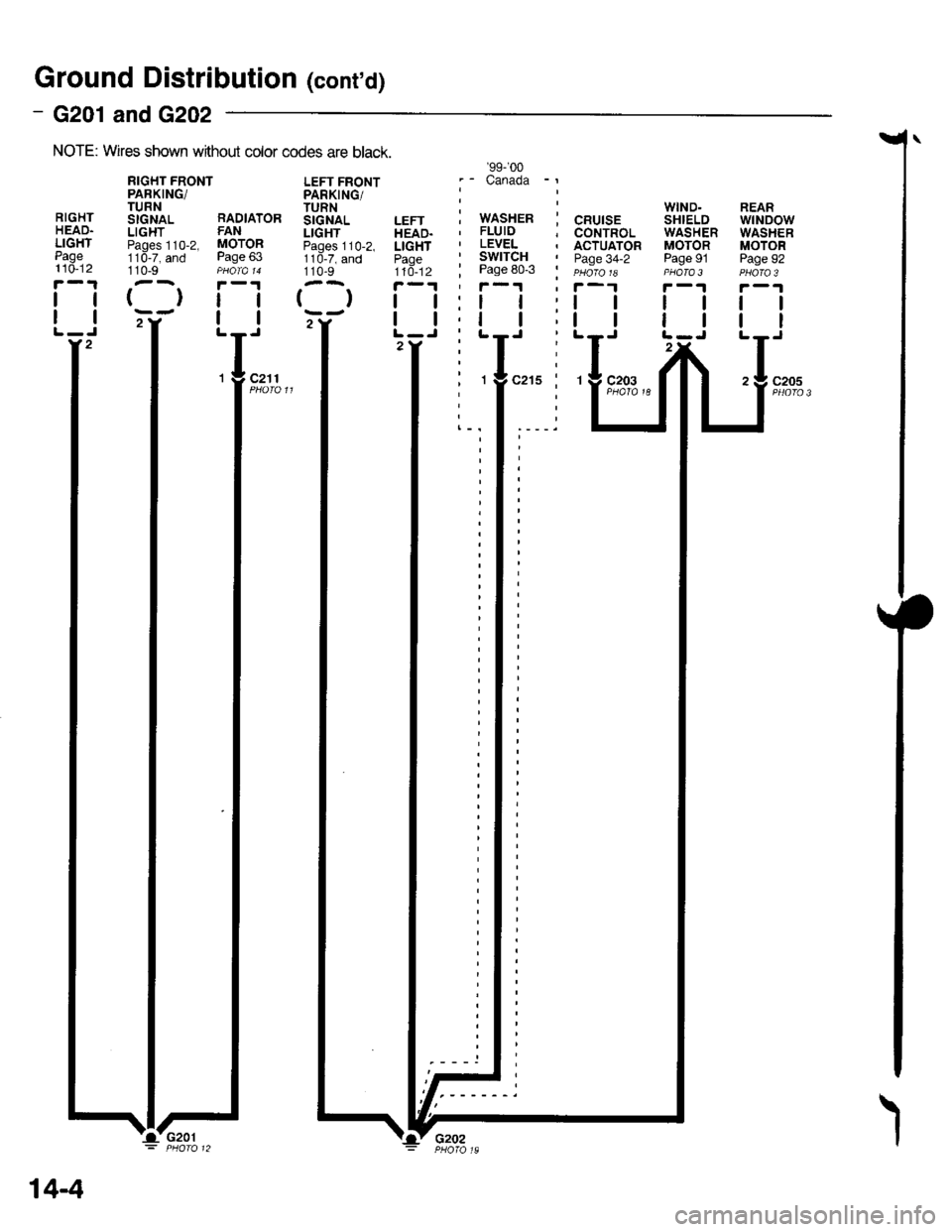
Ground Distributiofl (cont'd)
- G201 andG202
NOTE: Wires shown wrthout color codes are black.
RIGHTHEAD.LIGHTPage110-12
tl
tl
110-9
{}tl
tl
LEFT FRONTPARKING/TURNSIGNALLIGHTPages 110-2,1 10-7, and110-9
()
WIND.SHIELDWASHERMOTORPage 91PHOTA 3
ll
tl
REARwtNDowWASHERMOTORPage 92
tl
tt
c205
RIGHT FRONTPARKING/TURNStcNAL RADIATORLIGHT FANPaoes 110-2, MOTOR11d-7, and Page 63
'99-'�00
.- Canada -l
i wnsxen i cnurse, FLUID ; CONTROL' LEVEL . ACTUATOR' SWITCH I paoe 34-2; Page 80-3 i eu6ro re'f-1 ' f-1
2Y2
c211
14-4
I'G201'Lv G2o2
Page 1936 of 2189
![HONDA CIVIC 1999 6.G Workshop Manual ?uTii------lUNDER.OASHFUSE/RELAYBOX
UNDER-HOODFUSE/RELAYBOXfI,€! PtfiP
f#rntt)See PowerDistribution,
iT;;*-l
rr:_i
y;lftr,.:{
page 10-2.tJ---------J" Y 3,,t"?:"""""T
[]:.
i-?;;ffi;
i_f___
PGM- HONDA CIVIC 1999 6.G Workshop Manual ?uTii------lUNDER.OASHFUSE/RELAYBOX
UNDER-HOODFUSE/RELAYBOXfI,€! PtfiP
f#rntt)See PowerDistribution,
iT;;*-l
rr:_i
y;lftr,.:{
page 10-2.tJ---------J" Y 3,,t"?:"""""T
[]:.
i-?;;ffi;
i_f___
PGM-](/img/13/6068/w960_6068-1935.png)
?uTi'i'------lUNDER.OASHFUSE/RELAYBOX
UNDER-HOODFUSE/RELAYBOXfI,€! PtfiP
f#rntt)See PowerDistribution,
iT;;*-l
rr:_i
y;lftr,.:{'
page 10-2.tJ---------J" Y 3,,t"?:"""""T
[']':.
i-?;;ffi;
i_f___
PGM-FIMAINRELAY
;;II
;;;I
c't0'l
vtEw 28
TI
":{
c130Oerminals l4-17)
vlEw 52
I . (rGP1) i 1rGP2) - I
Power input
..���������������
SeePGM,FI
POWER.TRAINCONTROLMODULE(PcM)PHO|O 86
(cont'd)
\!
CW hansm|ssion_ control solonoids Ground I
t (HLC LS-) THLCLS+) (SCLS-) (SCLS'I iSH LS I rSHLS+j ISOLINHI lPGr) (PO2) (LG1) rLG2r IL-------i:---- ---------J
-T1
Tj
:1 ;
lruffil
GRNBLII
cl16(Terminals8-14)
vlEW 39BLK
CVTTRANS.MISSIONSOLENOID
See GroundDistribution,page 14-2.
BRN/BLK
PH.PL START SHtF'CONTROL CLUTCH CONTNOLUN€AR CONTNOL LINEARSOLENOID UI{EAR SOLENOIDsoLEltotD
:_-:_-___1
-t
1-! |
Ti11:a__J
BRN/BLK
39-13
Page 1946 of 2189
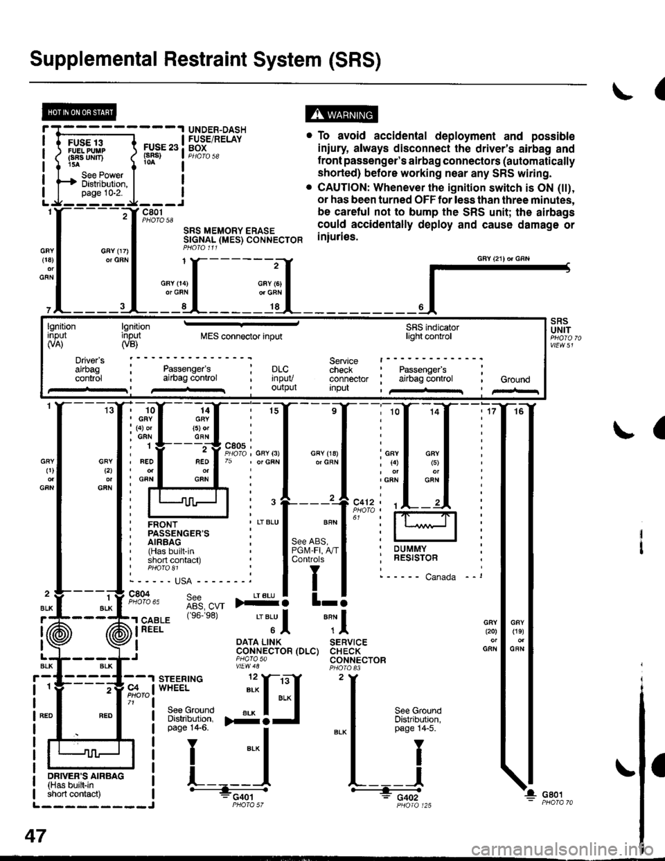
Supplemental Restraint System (SRS)
(
FUSE 13FUELPUUPFBA UMT)15A
See PowerDistibution,page 10-2.
FUSE 23(sRs)
c801PHOTO 58
SRS MEMORY ERASESTGNAL (MES) CONNECTORPHO|O 111
. To avoid accidental deployment and possible
iniury always disconnect the driver's airbag and
f ront passenger's airbag connectors (automatically
shorted) before working near any SRS wiring.
. CAUTION: Whenever the ignition switch is ON (tt),
or has been turned OFF for less than three minutes,
be caretul not to bump the SRS unit; the airbags
could accidentally deploy and cause damage or
iniuries.
UNDER-DASHFUSE/RELAYBOX
GFY 07)or GFN{18)
GFN
GFYt2l
GFN
GRY0)
GFN
2
ALK
J (ii
t\
GFY O4)or GRN
SRSUNIT
a
-ffiffi,*l-{
H!=";=_J
iffii'r:fi:*" i tH-
PHOIO 125short contact) | - FCqOtL_________J PHO|A 57
47
GAY (21) or GRN
lgnitionInput(VA)
Driver's
cont.ol
lgnitioninput(VB)MES connector inputSRS indicatorlighl control
Service t------check : Passengefs ;connector ; airbag control , GroundInpu , /+rr I pir-r
Passenger'sai|bag conlrol; prc..t rnpuv, Ourpul
14GRY(5) orGFN
rffi{{_ilil
i ffi i""'"1*"o,"'.1'' i lffil
ffirtu!-T:l
ir:r*::"."
ilstEl'{s6.e8'�
'"'Jl "Tl
, I oATA L|NK SERVTCE: CoNNECTOR (DLC) CHECK,J piarasa CONNECTORvtEw48