Brake HONDA CIVIC 1999 6.G Workshop Manual
[x] Cancel search | Manufacturer: HONDA, Model Year: 1999, Model line: CIVIC, Model: HONDA CIVIC 1999 6.GPages: 2189, PDF Size: 69.39 MB
Page 44 of 2189
Lift and Support Points
Floor Jack
Apply the parking brake and block the wheets thatare not being lifted.
When lifting the rear of the vehicle, put the gearshiftlever in reverse (Automatic transmission/Cw in Eposition).
Raise the vehicle high enough to insert the safetystands.
Adjust and place the safety stands so the vehiclewill be approxlmately level, then lower the vehicleonto them.
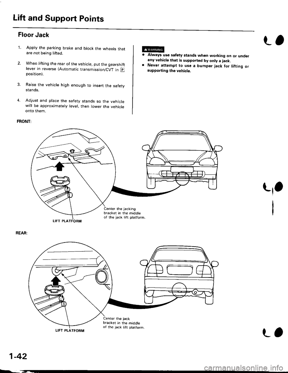
FRONT:
Always use safety stands whon working on or undelany vehicle that is supported by only a iack.Never attempt to use a bumper jack for lifting orsupporting the vehicle.
t,1.
REAR:
1-42
LIFT PLA
4.
Center the jacking
bracket in the middleof the iack lift platform.
Center the iackbracket in the middleof the jack lift ptatform.
-,-_
LIFT PLATFORM
L,
Page 45 of 2189
Towing
lf the vehicle needs to be towed, call a professional tow-
ing service. Never tow the vehicle behind another vehi
cle with iust a rope or chain lt is very dangerous'
Emergency Towing
There are three popular methods of towing a vehicle:
Flat-bed Equipment - The operator loads the vehicle on
the back of a truck. This is the best way of transporting the
vehicle.
Wheel Lift Equipment - The tow truck uses t\ivo pivoting
arms that go under the tires {front or rear} and lifts them
off the ground. The other two wheels remain on the
ground.
Sling-type Equipment - The tow truck uses metal cables
with hooks on the ends. These hooks go around parts of
the frame or suspension, and the cables lift that end of
the vehicle off the ground The vehicle's suspension and
body can be seriously damaged if this method of towing
is attemDted.
lf the vehicle cannot be transported by flat-bed. it should
be towed with the front wheels off the ground lf due to
damage, the vehicle must be towed with the front
wheels on the ground, do the following:
lvlanual Transmission and CW
. Release the parking brake
. Shift the transmission to neutral (CW to E position)'
Automatic Transmission
. Release the Parking brake.
. Sta rt the engine.
. Shift to LDll position, then E position.
. Turn oif the engine
CAUTION;
o lmploper towing preparation will damage ihe tfans-
mission. Follow the above procedute exaqtly lf you
cannot shift the tlansmission or start the engino
laulomatic transmissionl, yout vehicle must be trans-
ported on a flat-bed.
. lt is best to tow the vehicle no farther than 50 mil€s
(80 km), and ksop thE speed below 35 mph (55 km/hl
. Trying to lift 01 tow your vehicle by tho bump€F will
caus€ setious damagg. Ths bumpers are not dEigned
to supportthe vshicle's weigh.
tJO
1-43
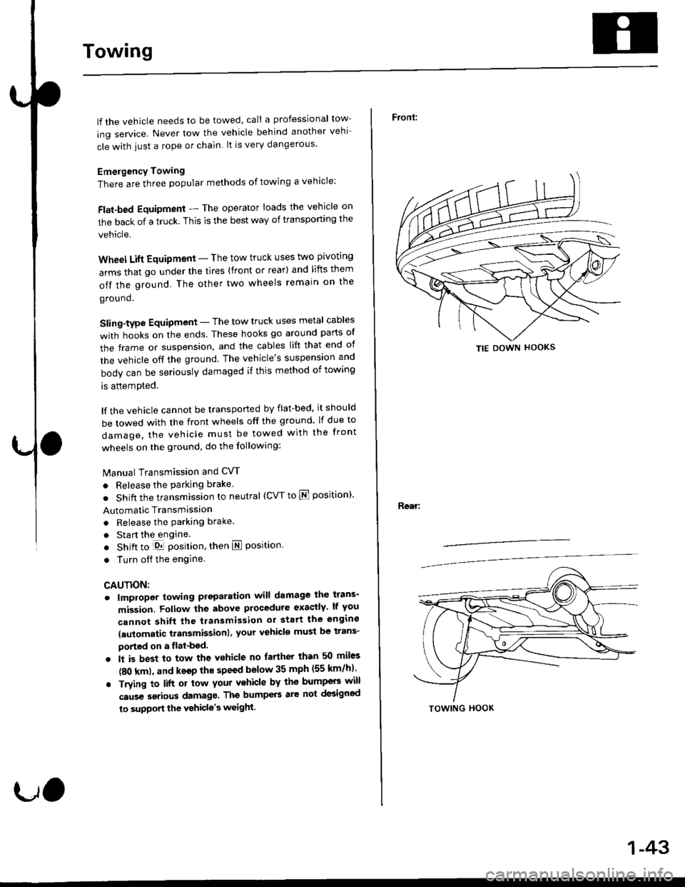
Front:
Rear:
TIE DOWN HOOKS
TOWING HOOK
Page 58 of 2189
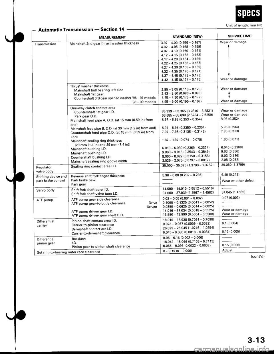
Automatic TnsmtsstonSection 14Un;t of length: mm {in)
r
MEASUREMENT
a
STANDARD INEW)SEBVICE LIMIT
TransmissionMainshaft 2nd gear thrust washer thickness
Thrust washer thicknessMainshaft ball bearing left sideMainshaft lst gear
Countershaft 3rd gear splined washer '96 97 models'98 - 00 models
One-way clutch contact area
Countershaft 1st gear LD.
Park gear O.D.Mainshaft feed pipe A, O.D. (at 15 mm (0.59 inlfrom
Mainshaft feed pipe B, O.D. (at 30 mm {1.2 in) from end)
Countershaft feed pipe O.D. lat 15 mm (0 59 in) from
eno)Mainshaft sealing ring thickness
129 mm 11.1 iniand 35 mm {1.4 in))
Mainshaft bushing l.D.
Mainshaft bushing LD.
Countershaft bushing LD.Mainshaft sealing ring goove width
3.97 4.00 10.156 - 0.157)4.02 - 4.05 (0.158 0.159)
4.07 - 4.10 (0.160 - 0.161)4.12 - 4.15 (0.162 0.163)
4.17 - 4.20 10.164 - 0.165)4.22 - 4.25 (0.166 - 0.167)4.27 - 4.30 (0.168-0.169)
4.32 - 4.35 (0.170 0.171)
4.37 - 4.40 10.172 - 0.173)
4.42 - 4.45 10.114 - 0.175l
1
I
+Wear or damage
2.95 - 3.05 {0.116 - 0.120)2.43 2.50 (0.096 - 0.098)4.45 - 4.50 (0.175 - 0.177i4.95 - 5.00 (0.195 0.197)
Wear or damage
+I
83.339 - 83.365 (3.2810 3.2821)
66.685 - 66.698 (2.6254 - 2.6259)
8.97 - 8.98 (0.353 - 0.354)
5.97 5.9810.2350 - 0.2354i7.97 - 7.98 (0.3138 - 0.3142)
1.87 - 1.97 {0.074 0.078)
6.0 r8 - 6.030 {0.2369 - 0.2374)
9.000 - 9.01s 10.3543-0.3549)8.000-8.022 (0.3150 - 0.3158)
2.025 - 2.015 l0.0197 -0.0417)
Wear or damageWear or darn age
8.95 (0.352J
5.95 (0.234)
7.95 (0.313)
1.80 (0.071)
6.045 (0.2380)
9.03 (0.356)
8.03 {0.316)2.08 (0.082)
Regulatorvalve body
Seating ring conlact area l.D.35.000 35.02511.3780 1.3782)35.050 (1.3799)
Shifting device andpark brake controlReverse shift fork Iinger thicknessPark brake pawl
Park gear
5.90 - 6.00 (0.232 - 0.236)5.40 (0.213)
lWear or other defect
Servo bodyShift fork shaft bore LD.
Shift fork shaft valve bore l.D.
14.000 - 14.010 (0.5512 - 0.5516)
37.000 - 37.039 (1.4567 - 1.4582)37.045 (1.4585)
ATF pumpATF pump gear side clearanceATF pump gear-to-body clearance DriveDaiven
ATF pump driven gear LD.ATF pump driven gear shaft O.D
0.03 -0.05 {0.001 - 0.002)0.1050 - 0.1325 (0.0041 - 0.0052)
0.0350 - 0.0625 (0.0014 - 0.0025)14.0'�|6 - 14.034 {0.5518 - 0.5525i13.980 13.990 (0.5504 0.5508)
0.07 (0.003)
Differentialcarrier
Pinion shaft contact area LD.
Carrier to'pinion clearanceDriveshaft contact are LD.
Carrier to-driveshaft clearance
18.010 18.028 {0.7091 0.7098)
0.023 - 0.057 (0.0009 -0.0022)
26.025 * 26.045 11.0246 1.0254)
0.045 - 0.086 (0.0018 - 0.0034)
0.1 {0.004)
0.12 {0.005)
Differentialprnron gearBacklasht.D.Pinion gear to-pinion shaft clearance
0.05 - 0.15 {0.002 - 0.006)18.042 - 18.066 (0.7103 - 0.7113i0.055 - 0.095 (0.0022 - 0.0037)ffi.oour
Set ring-to bearing outer race clearance0 - 0.15 (0 0.006)Adjust
(cont'd)
3-13
Page 59 of 2189
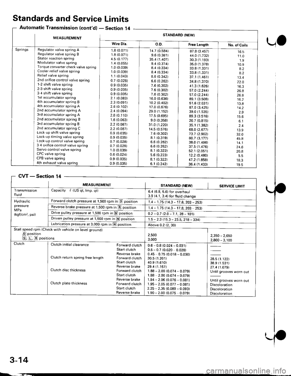
Standards and ServiceLimits
Section '14Automatic Transmission (cont'd)
UO
MEASUREMENTSTANDARD {NEW}
Wire Dia.o.D.Free LongthNo. ol CoilsHegulator valve spring ARegulato. valve spring BStator reaction springModulator valve springTorque convener check valve springCooler relief valve springRelief valve spring2nd oritice control valve spring1-2 shift valve spring2-3 sh ift valve spring3 4 shift valve spring'l st accumulator spring4th accumulator spring B4th accumulator spring A2nd accumulator spring A3rd accumulator spring A2nd accumulator spring B3rd acc!mulator spring B2nd accumulator spring CLock up shift valve springLock up timing valve springLock-up control valve spring3 4 ofifice control valve springServo control valve springCPC valve springCPB valve spring4th exhaust valve spring
Springs1.8 {0.071)1.8 {0.071)4.5 \O.117)1.4 (0.055)
1.0 10.039)1.0 (0.039)
1.1 (0.043)
0.7 (0.028)
0.9 (0.035)
0.9 (0.035)
0.9 (0.035)
2.1 (0.083)
2.3 (0.091)
2.610.102)2.4 (0.094)
2.8 (0.'110)
1.6 (0.063)
2.2 (0.087)
2.2 t0.041)0.9 (0.035)
0.9 (0.035)
0.7 (0.028)
0.7 (0.028)
1.0 (0.039)
0.6 (0.024)
0.9 {0.035)0.9 (0.035)
14.7 (0.584)
9.6 (0.381)
3s.4 (1.407)
9.4 (0.374)8.4 (0.334)
8.4 (0.334)
8.6 {0.342)6.6 (0.262)
7.6 (0.302)
7.6 (0.302)
7.6 (0.302)16.0 (0.636)10.2lo.402l17.0 {0.676)29.0 (1.152)
17.5 (0.6951
9.0 (0.358)
31.0 (1.220)
14.5 {0.576)7.6 (0.302)
8.1 (0.319)
6.610.262)6.6 (0.262)
8.1 (0.322)
5.6 (0.2231
8.1 10.322)6.1 10.242)
87.8 (3.457)
44.0 i.732l'30.3 (1.193)
35.0 {1.378)33.8 (1.331)
33.8 (1.331)
37.1 (1.461)
34.8 (1.370)
41.3 (1.626)
57.0 (2.2441
51 .0 \2.244189.1 {3.508)51.6 (2.031)
87.0 (3.425)
39.011.535)89.3 (3.516)
20.7 (0.815)
35.1 11.382)68.012.671173.7 12.902)80.7 (3.177)38.0 {1.496)37.5 fi.476)52.1 (2.051)
12.2 (0.480)
47.2 {1.858}36.4 {1.433)
16.511.01.910.94.24.213.422.016.326.826.a16.213.814.22.915.66.12.413.932.045.814.124.620.4
18.319.5
CVTSection 14
3-14
MEASUREMENTSTANDARD INEWISERVICE LIMITTransmissionfluidCapacity f {US qt, lmp. qt)6.4 {6.8, 5.6) for overhaul3.9 (4.1, 3.4) for fluid change
Hydraulicpressure
1kgflcm,, psi)
Forward clutch pressure at 1,500 rpm in E position1.4 - 1.15 114.3 - 11.A,203 - 2531Reverse brake pressure at 1,500 rpm in E position1.4 - 1.75 (14.3 11.8,203 2531Dr;ve pulley pressure at 1,500 rpm in E posrtrono.2 -0.7 12.0 -7.1,28- 1011Driven pulley pressure at 1,500 rpm in N positionr.5 - 2.3 115.3 - 23.5, 218 - 334)Lubrication pressure at 3,000 rpm in E posrtronAbove 0.212,30)Stall speed fpm (Check with vehicle on level ground)
E position
E, E, El positions2,5003,0002,350 - 2,6502,800 - 3, r00ClutchClutch initial clearance Forward clutchStart clutchReverse brakeClutch return spring free length Forward clutchStart clutchReverse brakeClutch disc thickness Forward clutchStart clutchReverse brakeClutch plate thickness Forward clutchSta rt clutchReverse brake
0.6 - 0.8 (0.024 - 0.031)0.5 - 0.7 (0.020 0.028)0.45 - 0.75 (0.018 - 0.030)30.5 {1.201)40.9 (1.610)
29.4 (1.157)
1.88 - 2.00 (0.074- 0.079)1.88 2.00 (0.074 - 0.079)1.94 - 2.06 (0.076 - 0.081)1.95 - 2.05 (0.077 -0.081)
2.25 2.35 (0.089 - 0.093)1.90 - 2.00 (0.075 0.079)
,*x.ar}38.9 (1.531)
27.411.019l'Until grooves worn out
Until grooves worn outDiscolorationDiscolorationDiscoloration
L.
Page 60 of 2189
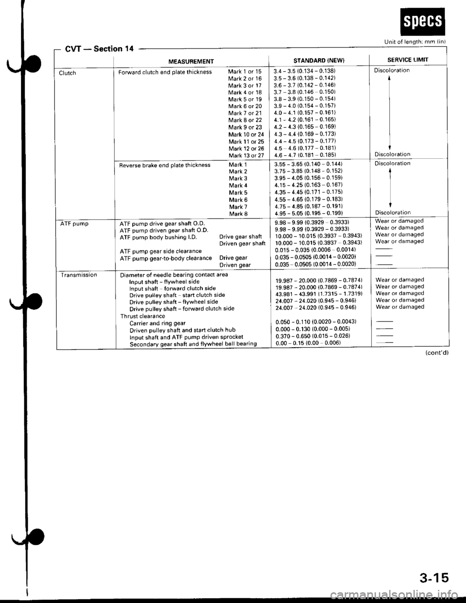
cwSection 14[Jnit of length: mm (in)
MEASUBEMENTSTANDARD {NEW}SERVICE LIMIT
Forward clutch end plate thickness Mark 1 or 15Mark 2 or 16Mark 3 or 17Mark 4 or 18Mark 5 or 19Mark 6 or 20Mark 7 or 21Mark 8 or 22Mark I or 23Mark 10 or 24Mark 11 or 25Mark 12 or 26Matk 13 ot 21
3.4 - 3.5 10.134 - 0.138)
3.5 - 3.6 (0.138 - 0.142)3.6 - 3.7 (0.142 - 0.146)3.7 3.8 (0.146 0.150)3.8 - 3.9 (0.150 - 0.154)3.9 - 4.0 (0.154 - 0.157i4.0 - 4.1 (0.157 - 0.161)4.1 - 4.2 (0.161 - 0.165)4.2 - 4.3 (0.165 - 0.169)4.3 - 4.4 (0.169 - 0.173)4.4 - 4.5 10.173 - 0.177i4.5 4.6 (0.177 0.181)4.6 - 4.7 (0.181 - 0.185)
Discoloration
Discoloration
Reverse brake end plate thickness Mark 1Mark 2Mark 3Mark 4\44 rk 5Mark 6Mark 7Mark 8
3.55 - 3.65 (0.140 0.144)3.75 - 3.85 10.148 - 0.152)
3.95 - 4.05 (0.156 - 0.159i4.15 - 4.25 (0.163 0.167)4.35 - 4.45 (0.171 - 0.175)
4.55 - 4.65 (0.179 - 0.183)4.75 - 4.85 (0.187 - 0.191)4.95 - 5.05 (0.195 - 0.199)
Discoloration
1
IDiscoloration
ATF pumpATF pump drive gear shaft O.D.ATF pump driven gear shaft O.D.ATF pump body bushing l.D. Drive gear shaftDriven gear shaft
ATF pump gear side clearanceATF pump gear-to-body clearance Drive gear
Driven gear
9.98 - 9.99 (0.3929 0.3933)9.98 - 9.99 {0.3929 - 0.3933)10.000 - 10.015 (0.3937 0.3943)10.000 - 10.015 (0.3937 0.3943)
0.01s - 0.035 (0.0006 0.0014)
0.035 - 0.0505 (0.0014- 0.0020)
0.035 - 0.0505 (0.0014 - 0.0020)
Wear or damagedWear or damagedWear or damagedWear or damaged
TransmissionDiameter of needle bearing contact areaInput shaft - flywheel sideInput shaft forward clutch sideDrive pulley shaft - start clutch sideDrive pulley shaft - flywheel side
Drive pulley shaft - forward clutch side
Thrust clearanceCarrier and ring gear
Driven pulley shaft and start clutch hub
Input shaft and ATF pump driven sprocketSecondary gear shaft and flywheel ball bearing
19.987 - 20.000 (0.7869 - 0.7874)19.987 - 20.000 (0.7869 - 0.7874)43.981 - 43.991 (1.7315 - 1.7319)24.007 - 24.020 (0.945 - 0.946)24.007 - 24.020 (0.945 - 0.946)
0.050 - 0.110 (0.0020 - 0.0043)
0.000 - 0.130 10.000 - 0.005)
0.370 - 0.650 (0.015 - 0.026)0.00 0.15 (0.00 0.006)
Wear or damagedWear or damagedWear or damagedWear or damagedWear or damaged
(cont'd)
3-15
Page 61 of 2189
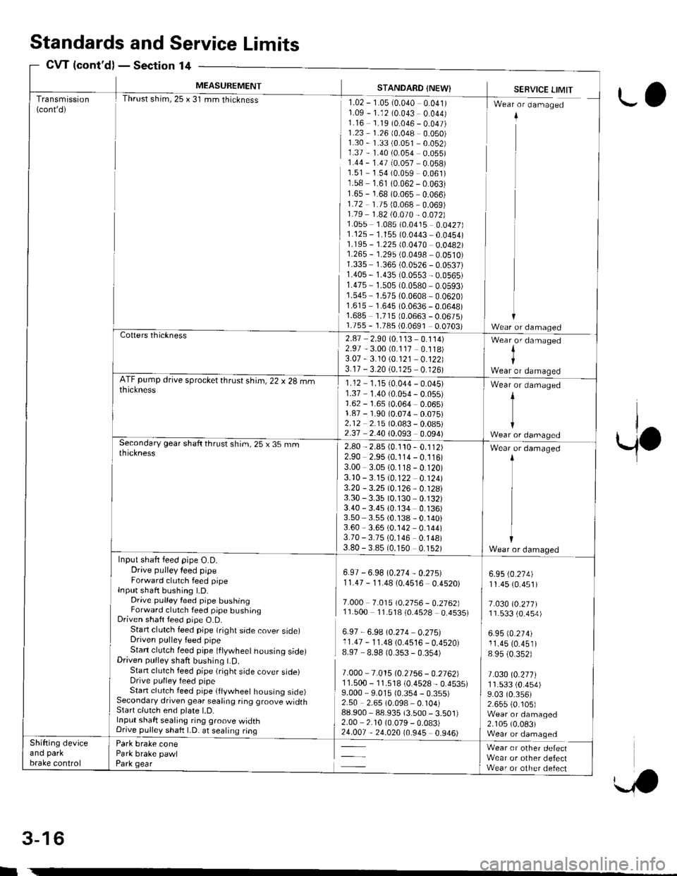
Transmission(cont'd)
MEASUREMENT
Thrust shim,25 x 31 mm thickness
STANDARD {NEW}
rlz-r-osr-o.o+o oolrr1.09 - 1.12 (0.043 0.044)1.16 1.19 (0.046 - 0.047)1.23 1.26 (0.048 0.050)1.30 - 1.33 (0.051 0.052)1.37 - 1.40 (0.054 0.055)1.44 - 1.47 (0.057 0.058)1.51 1.54 (0.059 0.061)1.58 1.61 (0.062 - 0.063)1.65 - 1.68 (0.065 0.066)1.72 1.75 {0.068 0.069)1.79 1 .a2 t0.O10 - 0.012]}1.055 1.085 (0.0415 0.0427)1.125 - 1.155 (0.0443 0.0454)1.195 - '�I.225 (0.0470 0.0482)1.265 - 1.29s (0.0498 0.0510)1.335 1.365 (0.0526 - 0.0537)1.40s - 1.435 (0.0553 - 0.0565)r.475 1.505 {0.0580 0.0593)1.545 1.575 (0.0608 0.0620)1.615 1.645 (0.0636 - 0.0648)1.685 1.71510.0663 - 0.0675)1.755 - 1.785 {0.0691 0.0703)
SERVICE LIMIT
I Wr"r - d-"-"g"d
ii
11
ir
Cotters thickness2.87 - 2.90 (0.1 13 - 0.114)2.97 - 3.00 (0.117 0.118)3.07 -3.10 \0.121 0.122)3.17 - 3.20 (0.125 0.126)
Wear,or damaged
IWear or damaoedATF pump drive sprocket thrust shim, 22 x 28 mmthickness1.12 1.1510.044 - 0.045)1.37 1.40 (0.054 - 0.055)1.62 - 1.65 (0.064 0.065)1.87 - 1.90 (0.074,0.075)2.12 2.15 (0.083 - 0.08s)2.37 2.40 (0.093 0.094)
Wear or damaged
t
{Wear or damagedSecondary gear shaft thrust shim, 25 x 35 rnmthickness2.80 - 2.85 (0.1'�t0 - 0.112)2.90 2.95 (0.114 - 0.116)3.00 3.05 (0.118 - 0.120)3.10 -3.15 10.122 0.124)3.20 - 3.25 (0.126, 0.128i3.30 - 3.35 (0.130 0.132)3.40 - 3.4s 10.134 0.136)3.50 3.55 (0.138 - 0.140)3.60,3.65 (0.142 0.144)3.70 - 3.75 (0.146 0.148)3.80 - 3.8510.150 0.152)
Wear or damaged
Wear or damaqedInput shaft feed pipe O.D.Drive pulley leed pipeForward clutch feed pipeInput shaft bushing t.D.Drive pulley feed pipe bushingForward clutch feed pipe bushingDriven shaft feed pipe O.D.Start clutch feed pipe (right side cover side)Driven pulley feed pipeStan clutch feed pipe (ftywheet housing side)Driven pulley shaft bushing LD.Stan clutch feed pipe (right side cover sroerDrive pulley feed pipeStart clutch feed pipe (flywheel housing side)Secondary driven gear sealing ring groove widthStart clutch end plate l.D.Input shaft sealing ring groove widthDnve pullev shaft LD. at sealing ring
Park brake conePark brake pawlPark gear
6.97 - 6.98 (0.274 - 0.27s)11.47 - 1'1.48 (0.4516 0.4520)
7.O0O 7.0t510.2156 - 0.2762]l11.500 11.518 (0.4528 0.4535)
6.97 - 6.9A \0.214 0.275:l11.47 - 11.48 (0.4516 _ 0.4520)8.97 8.98 10.353 - 0.354)
7.000 7.015 (0.2756 - 0.2762)1 1.500 - '11.518 (0.4528 - 0.4535)9.000 9.015 10.354 - 0.355)2.50 2.65 (0.098 0.104)88.900,88.935 (3.500 - 3.501)2.00 2.10 10.079 - 0.083)
5*
6.95 (0.274)
11.45 (0.451)
7.030 (0.277)11.533 (0.4s4)
6.95 (0.274)
11.45 (0.451)
8 95 (0.352)
t.030l0.2t7l1r.533 (0.454)
9.03 (0.356)2.655 (0. r05)Wear or damaged2.105 (0.083)Wear or damaqedShifting deviceano parKbrake control
Wear or other defectWear or other defectWear or other defect
Standardsand Service Limits
CW {cont'd)Section 14
rl
w
3-16
ro
Page 63 of 2189
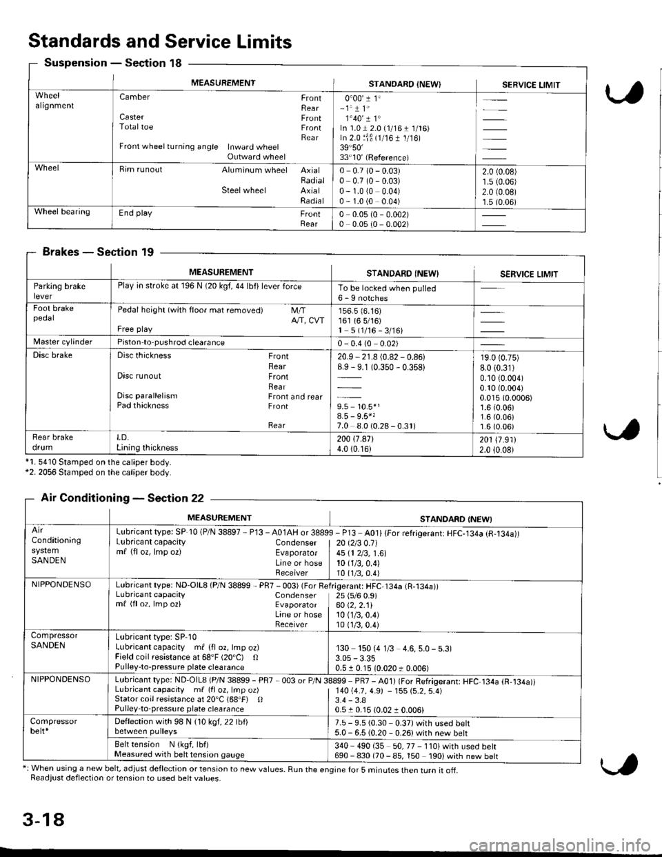
MEASUREMENTSTANOARO INEW}SERVICE LIMIT
algnmenlCamber FrontRearCaster FrontTotaltoe FrontBearFront wheel turning angle Inward wheelOutward wheel
0"00'1 1"-1.1 1'1'40'� I 1"In'1.01 2.0 {1/16 t 1/'16)In 2.0 ljB (1/161 1/16)39.50'�33'10'(Reference)
Bim runout Aluminum wheel AxialBadialSteelwheel AxialRadla I
0 0.7 (0 - 0.03)0- 0.7 (0 - 0.03)0 - 1.0 (0 0.04)0 - 1.0 (0 0.04)
2.0 (0.08)
1.5 10.06)2.0 {0.0B)1.5 (0.06)Wheel bearingEnd play FrontRear0 0.0s (0 - 0.002)0 0.05 (0 0.002)
Standards and Service Limits
Suspension - Section 18
Brakes - Section 19
*1. 5410 Stamped on the caliper body.*2. 2056 Stamped on the caliper body.
Air Conditioning - Section 22
*: When using a new belt, adjust deflection or tension to new values. Run the engine for 5 minutes then turn it of{.Readjust deflection or tension to used belt values.
3-18
MEASUREMENTSTANDARO INEWISERVICE LIMIT
Parklng brakePlay in stroke at 196 N (20 kgf, 44 lbfi lever forceTo be locked when pulled6 - I notchesFoot brakepeoalPedal height (with floor mat removed) M/TA/'T, CVTFree play
156.5 {6.16)161 (6 5/16)1 5(1/16-3/16)
Master cvlinderPiston to pushrod clearance0 - 0.4 (0 0.02)
Disc brakeDisc thickness FrontRearDisc runout FrontRearDisc parallelism Front and rearPad thackness Front
Rear
20.9 - 21.8 (0.82 - 0.86)8.9 - 9.1 (0.350 - 0.358)
9.5 10.5*'8.5 - 9.5*'7.0 8.0 (0.28-0.3r)
19.0 (0.75)
8.0 (0.31)
0.10 (0.004)
0.10 (0.004)
0.015 (0.0006)
1.6 (0.06)1.6 (0.06)'r.6 (0.06)
Rear brakedrumLD.Lining thickness200 17.a7l4.0 (0.16)201 \7 .9112.0 {0.08}
MEASUREMENTSTANDARD INEWI
Conditioning
SANDEN
Lubricant type: SP 10 (P/N 38897 - Pl3 - A01AH or 3889Lubricant capacity Condensermf (floz, lmp oz) EvaporatorLine or hoseReceiver
I - P13 A0li lFor refrigerant: HFC-134a (R,134a))
| 20 \2t3 0.11
I 45 (1 2/3, 1.6)10 (1/3,0.4)
10 t1/3,0.4)NIPPONDENSOLubricant type: ND'O|L8 (P/N 38899 - PR7 - 003) (For ReLubricant capacity Condensermf (floz, lmp oz) EvaporatorLine or hoseReceiver
f.igerant: HFC,134a (R-134a))25 (s/6 0.9)60 (2,2.11
10 (1/3,0.4)
10 (1/3.0.4)
CompressorSANDENLubricant type: SP-10Lubricant capacity ml lfl oz, lmp oz)Field coil resistance at 68'F (20"C) OPulley-to-pressure plate clearance
130 150 (4 1/3 4.6, 5.0 - 5.3)
0.5 r 0.15 10.020 t 0.006)
NIPPONDENSOLubricant type: ND-OlL8 {P/N 38899 - PR7 ,003 or P/N 38899 pR7 - AO1) (For Refrigerant: HFC 134a {R,134a))Lubricant capacity m{(fl oz, lrnpoz) | 14O(4.7,4.9J -15S{5.2.5.4)Stator coil resistance at 20'C (68.F) 0Pulley-to-pressure plate clearance3.4 - 3.80.510.15 (0.0210.006)
Compressorbelt*Deffection with 98 N (1Okgl.22lbllbetween pulleys7.5 - 9.5 (0.30 0.37) with used belt5.0 - 6.5 (0.20 - 0.26)with new belt
Belt tension N (kgf, lbf)Measured with belt tension gauge340 490 i35 50, 77 - 110) with used bell690 - 830 (70 - 85, 150 190) with new belt
Page 67 of 2189
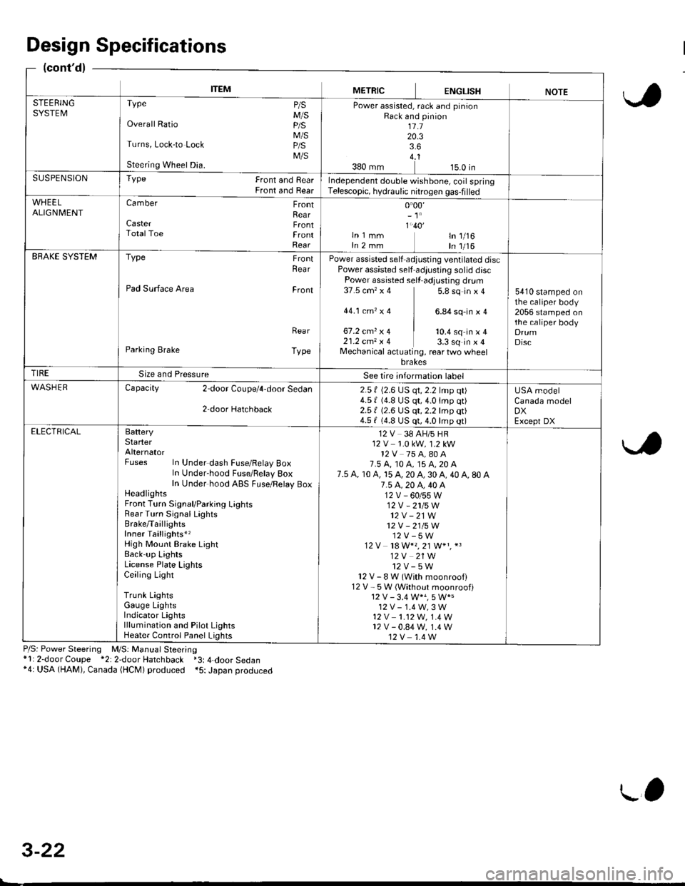
ITEMMETRICENGLISHNOTESTEERINGSYSTEMTvpe P/sM/SOverall Ratio p/S
M/STurns, Lock-to Lock p/S
M/SSteering Wheel Dia.
Power assisted, rack and pinionRack and pinion1l.120.33.64..1380 mm 15.0 inSUSPENSIONTYPe Front and RearFront and RearIndependent double wishbone, coil springTelescopic, hydraulic nitrogen gas-filled
WHEELALIGN| 4ENTCamber FrontRearCaster F.ontTotalToe FrontRear
0.00,- 't'
1.40'ln 1 mm ln 1/16In 2 mm In 1/16EBAKE SYSTEMType FrontRea r
Pad Surface Area Front
Rea r
Parking Brake Type
Power assisted self adjusting ventilated discPower assisted self adiustjng solid discPower assisted sell adjusting dr!m37.5 cm'�x 4 5.8 sq in x 4
44.1ctn,x4 ] 6.84sq-inxa
67.2 cmz x 4 | to.+ sq in ' I21.2 cm, x 4 3.3 sq in x 4Mechanical actuating, rear two wheelbrakes
5410 stamped onthe caliper body2056 stamped onthe caliper bodyDrumDisc
TIRESize and PressureSee lire intormation label
WASHERCapacity 2door Coupe/4,door Sedan
2,door Hatchback
2.5 f (2.6 LJS qt, 2.2 lmp qt)4.5 | (4.8 US qt,4.0lmp qt)2.51 (2.6 US qt, 2.2 lmp qt)4.5 f (4.8 US qt, 4.0 lmp qt)
USA modelCanada modelDXExcept DXELECTRICALBafteryStarterAlternatorFuses In Under dash Fuse/Felay BoxIn Under-hood Fuse/Belay 8oxIn Under hood ABS FLrse/Relay BoxHeadlightsFront Turn Signal/Parking LightsRear Turn Signal LaghtsBrake/TaillightsInner Taillights*,High Mount Brake LightBack up LightsLicense Plate LightsCeiling Light
Trunk LightsGauge LightsIndicator Lightslllumination and Pilot LightsHeater Control Panel Lights
12 V 38 AH/5 HR12 V 1.0 kW, 1.2 kW12V 75 A,80 A7.5 A, t0 A, 15 A, 20 A7.5 A, 10 A, 15 A, 20 A, 30 A, 40 A, 80 A7.5 4.20 A, 40 A12V_60/55W12V -2115W
12V - 21W12V - 21/5W12V-5W12 V 18 W*" 21 W+" *3
12V 21W12v-5wl2V-8W(Withmoonroofl12 V - 5W (Without moonroof)
12V-1.4W,3W't2 v 1.12W. 1.4 W12v-0.84w, 1.4 W12V 1.4 W
Design Specifications
(cont'd)
P/S: Power Steering M/S: Manual Steering*l: 2-door Coupe *2: 2door Hatchback *3: 4-door Sedan*4: USA (HAM), Canada (HCM) produced *5: Japan produced
3-22
L'
Page 72 of 2189
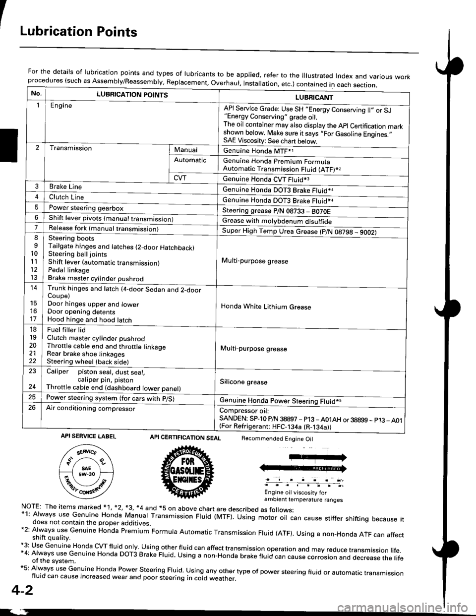
ILubrication Points
For the details of lubrication points and types of lubricants to be applied, refer to the lllustrated Index and various workprocedures (such as Assembly/Reassembly, Replacement, Overhaul. Installation, etc.) contained in each section.
No.LUBRICATION POINTS
Engine
LUBRICANT
"Energy Conserving" grade oil,The oil container may also display the Apl Certification markshown below. Make sure it says ,,For Gasoline Engines.,,SAE Viscosity: See chart below,
I
TransmissionManualGenuine Honda MTF*1
Genuine Honda Premium FormulaAutomatic Transmission Fluid (ATF)*,
Genuine Honda CVT Fluid*3
Genuine Honda DOT3 Brake Fluid*a
Automatic
CVT
3Brake Line
ClL,tci t""e4
I
Genuine Honda DOT3 Brake Fluid*aPower steering gearboxSteering grease P/N 08733 - BO70EShift lever pivots (manual transmission)Grease with molybdenum disulfide7-:ti
9
10'l'l
l3
14
't7
18
19
20
2122
Release fork (manual trancmi
Shift lever (automatic transmission)Pedal linkageBrake master cylinder pushrod
Super High Temp Urea crease (p/N 08798 - 9OO2)
i Multi-purpose grease
I
I
Honda White Lithium Grease
Multi-purpose grease
Silicone grease
@
Trunk hinges and latch (4-door Sedan and 2-doorCoupe)Door hinges upper and lowerDoor opening detentsHood hinge and hood latch-FUet T ter ttd
Clutch master cylinder pushrodThrottle cable end and throttle linkageRear brake shoe linkagesSteering wheel (back side)
23
E-
Caliper piston seal, dust seal,caliper pin. pistonThrottle cable end (dashboard lower panel)
Power steering system (for cars with p/S)
Air conditioning compressorComDressor oil:SANDEN: SPlo P/N 38897 - p13 -A01AH or 38899 - p13_ A01{For Refrigerant: HFC-134a (R-134a))
CERTIFICATION SEAL
ffi
NorE: The items m arked * 1, *2, +3, *4 and +5 on above chan are described as folows:*1: Always use Genuine Honda Manual Transmission Fluid (MTF). Using motor oil can cause stiffer shifting because itdoes not contain the proper additives.*2: Always use Genuine Honda premium Formula Automatic Transmission Fluid (ATF). Using a non-Honda ATF can affectshift quality.+3: Use Genuine Honda cVTfluid only usingotherfluid can affect tra nsmission operation and may reduce transmission life.*4: Always use Genuine Honda DoT3 Brake Fluid. Using a non-Honda brake fluid can cause corrosion and dec.ease the lifeof the svstem.*5: Always use Genuine Honda Power steering Fluid. using any other type of power steering fluid or automatrc transmissionfluid can cause increased wear and poor steering in cold weather.
4-2
Recommended Engine Oil
Engine oil viscosity forambrent temperature ranges
API SERVICE LABEL
Page 98 of 2189
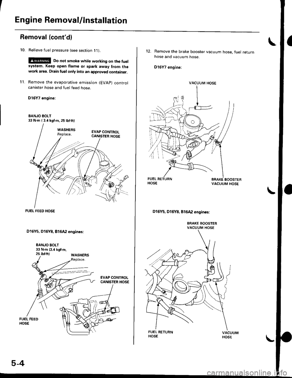
Engine Removal/lnstallation
Removal (cont'dl
10. Relieve fuel pressure (see section l1).
!@ Do not smoke while working on the fuelsystem, Keep open flame or spark away from thewolk area. Drain fuel only inlo an approved container.
11. Remove the evaporative emission (EVAP) controlcanister hose and fuel feed hose.
D16Y7 engine:
BANJO BOLT33 N m ( 3.it lgt m, 25 lbt.ft)
FUEI- FEED HOSE
D16Y5, D16Y8, Bt642 engines:
5-4
I
12. Remove the brake
hose and vacuum
D16Y7 engine:
booster vacuum hose, fuel returnhose.
VACUUM HOSE
Dl6Y5, D16Y8, Bl642 enginos:
BRAKE BOOSTERVACUUM HOSE