Counter shaft HONDA CIVIC 1999 6.G Workshop Manual
[x] Cancel search | Manufacturer: HONDA, Model Year: 1999, Model line: CIVIC, Model: HONDA CIVIC 1999 6.GPages: 2189, PDF Size: 69.39 MB
Page 53 of 2189
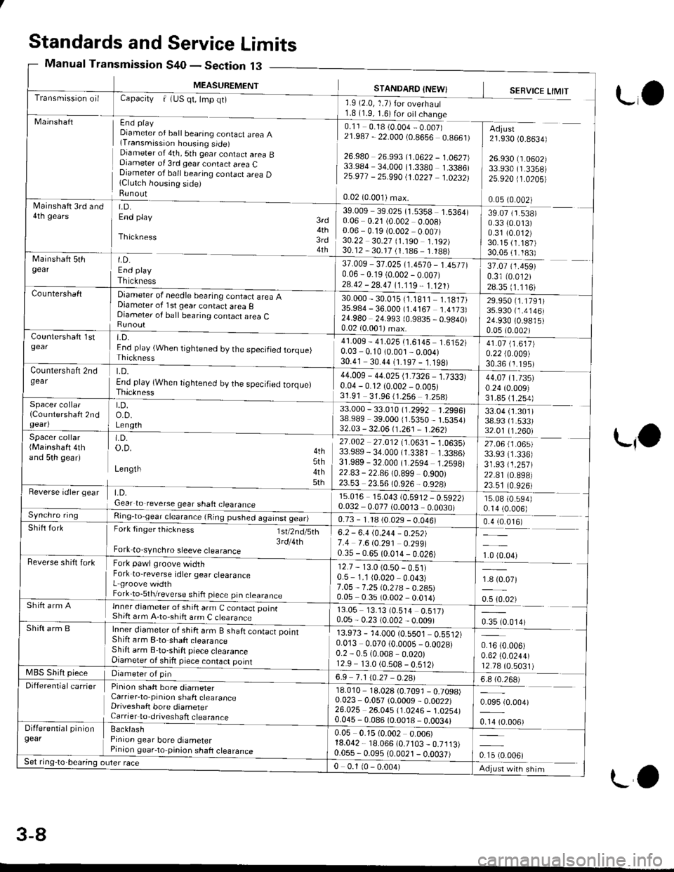
Standards and Service Limits
Manual Transmission S40 - Section 13
MEASUREMENT
Capacity | (US qt, tmp qt)
End playDiameter of ball bearing contact area A(Transmission housing side)Diameter of 4th, 5th gear contact area BDiameter of 3rd gear contact area CDiameter of ball bearing contact area D(Clutch housing side)Bunout
STANDARD INEW}'1.9 (2.0, 1.7)for overhaul1.8 (1.9, 1.6) for oitchange
0.11 0.18 (0.004 _ 0.007)21.987 - 22.000 (0.8656 0.8661)
26.980 26.993 (1.0622 _ 1.0627)33.984 34.000 (1.3380 1.3386)25.917 - 25.99011.0227 1.0232)
0.02 (0.001) max.
SEBVICE LIMIT
ro
MainshaftAdjust21.930 (0.8634)
26.930 ('1.0602i33.930 (1.3358)
25.92011.0205)
0.05 (0.002)
39.07 ('r.538)
0.33 {0.013)0.31 (0.012)
30.15 (1.187)
30.05 (1.183)
37.07 {1.459)0.31 (0.0'12)
28.35 (1.116)
LrO
39.009 39.025 (1.5358 1.5364)0.06 0.21 (0.002 0.008)0.06 0.19 (0.002 0.007)30.22 30.21 (1.190 1.192)30.12 - 30.17 (1.186 1.188)
37.009 37.025 (1.4570 _ 1.4577)0.06 - 0.19 (0.002 - 0.007)28.42 - 2a.47 11.119,1.1211Countershaft Diameter of needle bearing contact area ADjameter of lst gear contact area gDiameter of ball bearing contact area CRunout
30.000- 30.015 {1.181 1 - 1.1817)35.984 - 36.000 (1.4167 1.4173)24.980 24.993 (0.9835 - 0.9840)0.02 (0.001)max.
29.950 (1.1791)3s.930 r.4146)24.930 (0.9815)0.0s (0.002)
End play (When tightened by the specified torque)Thickness
41.009 - 41.025 ('�t.6145 1.6152)0.03 0.10 (0.001 _ 0.004)30.41 30.44 (1.197 - 1 198)
41 .01 11.617J0.22 (0.009)
30.36 (1.195)
gear End ptay (When tightened by the specified torque)44.009 - 44.025 (1.7326 1.7333)0.04 - 0.12 (0.002 - 0 005)31.91 31.96 (1.256 1.258)
44.01 11.t35)0.24 (0.009)
31.85 (1.2s4)
33.04 {1.301)38.93 (1.533)32.01 (1.260)
27.06 (1.065)
33.93 (1.336)
3r.93 {1.257)22.81 (0.898)
23.51 (0.926)
15.08 (0.594)
0.14 (0.006)
0.4 (0.016)
0.16 (0.006)
o.6210.0244112.78 (0.5031)
t.D.o. D.Length
33.000 - 33.010 (1.2992 1.2996)38.989 39.000 11.53s0_ 1.53s4)32.03 - 32.06 tl.261 - 1.2621Spacer collar(Mainshaft 4thand 5th gear)
Beverse rdler gear LD.Gear to reverse gear shaft cjearance
27.002 27.012 (1.0631 _ 1.0635)33.989 - 34.000 (1.3381 - 1.3386)3r.989 - 32.000 (1.2594 1.2598)22.83 - 22.86 (0.899 0.900)23.53 23.56 (0.926 - 0.928)
rs.016 15.043 (0.5912 _ 0.5922)0.032 0.077 (0.0013 _ 0.0030)Ring-to gear clearance {Ring pushed against gear)0.73 - 1.l8 (0 029 - 0.046)Fork finger thickness
Fork to-synchro sleeve clearance
lsv2nd/sth I 6.2 - 6.410.244 - O.ZS2)3rdl4th 7.4 i.6lO 2g1 O 2ggt0.35 - 0.65 (0.014 - 0.026)Beverse shitt fork Fork pawl groove widthFork to-reverse idler gear clearanceL groove widthFork'to-5th/reverse shift piece pin clearance
12.7 - 13.0 (0.50 _ 0.51)0.5 1. t (0.020 0.043)7 .05 - 7 .25 tO.21A - 0.28510.05 0.35 (0.002 0.014)Sh ift a rm A tnner diameter of sh ift arm C contact ffiShift arr14-go "L;L ".m C clearance13.05 13.13 (0.514 0.517)0.05 - 0.23 (0.002 _ 0.009)Inner diameter of shift arm B shaft contact pointShift arm 8-to shaft clearanceShift arm B to-shift piece clearanceDiameter of shift piece contact point
13.973 - 14.000 (0.5501 0.5512)0.013 0.070 (0.0005 _ 0.0028)0.2 - 0.5 {0.008 0.020)12.9 13.0 (0.508 - 0.512)MBS Shift prece Diameter of pin6.9 7 .1 \O.27 0 2A)
0.095 (0.004)
0.14 (0.006)
Adjust with shim
Differenlial carrier Pinion shaft bore diameterCarrier-to pinion shaft clearanceDriveshaft bore diameterCarrier to,driveshaft clearance
18.010 18.028 (0.7091 _ 0.7098)0.023 0.057 (0.0009 - 0.0022)26.025 26.04s {1.0246_ 1.0254)0.045 - 0.086 (0.0018 0.0034)BacklashPinion gear bore diameterPinion gear-to pinion shaft clearance
0.05 0.15 (0.002 0.006)18.042 - 18.066 (0.7103 _ 0.7113)0.055 - 0.095 {0.0021 _ o.oo37)
0 0.1 10 - 0.004)
3-8
LO
Page 57 of 2189
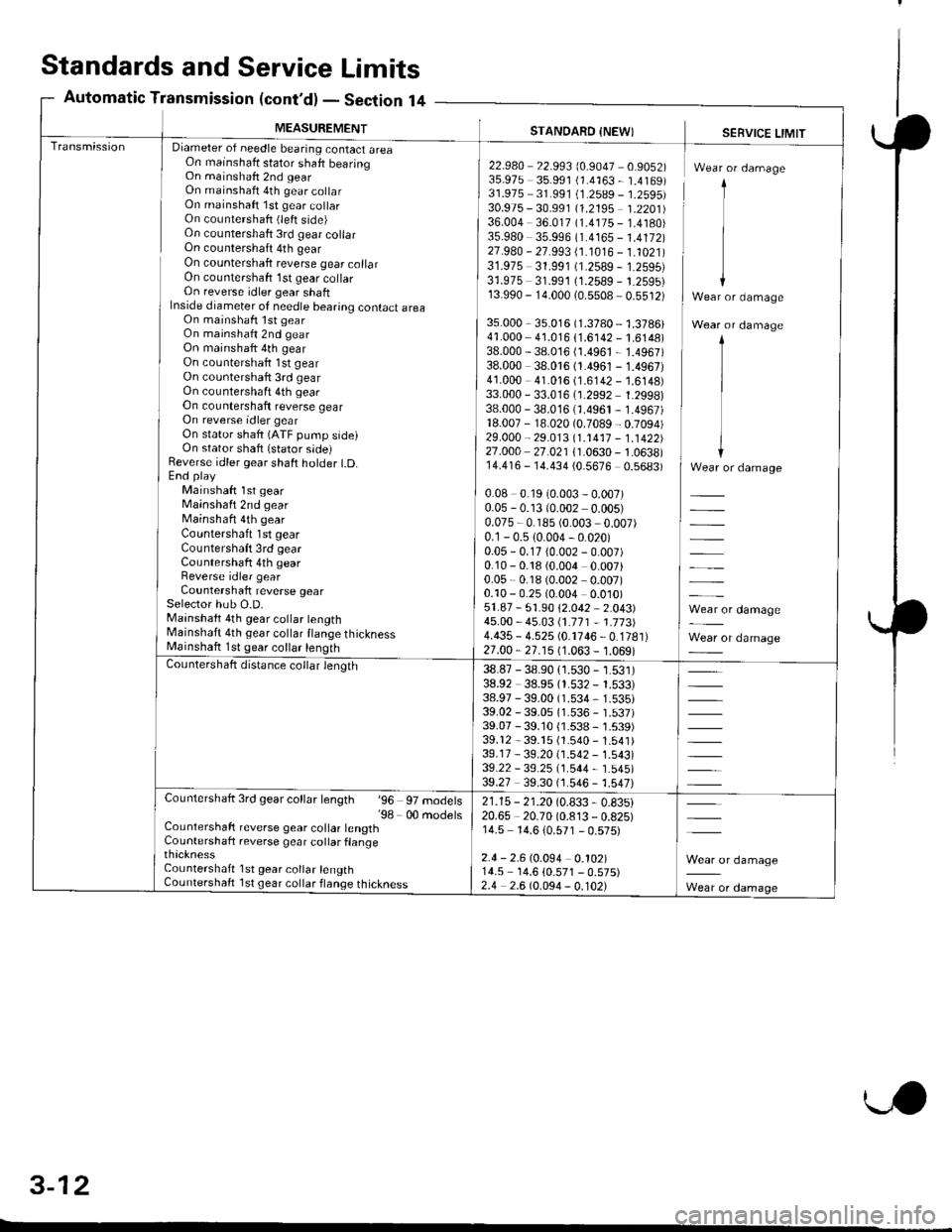
Standards and Service Limits
Automatic Transmission (cont'd) - Section l4
MEASUREMENTSTANOARD {NEW)SERVICE LIMITDiameter of needle bearing contact areaOn mainshaft stator shaft bearingOn mainshaft 2nd gearOn mainshaft 4th gear collarOn mainshaft 1st gear collarOn countershaft (left side)On countershaft 3rd gear collarOn countershaft 4th gearOn countershaft reverse gear collarOn countershaft 1st gear collarOn reverse idler gear shaftInside diameter of needle bearing contact areaOn mainshaft 1st gearOn mainshaft 2nd gearOn mainshaft 4th gearOn countershaft 1st gearOn countershaft 3rd gearOn countershaft 4th gearOn countershaft reverse gearOn reverse idler gearOn stator shaft (ATF pump sideiOn stator shalt (stator side)Reverse idler gear shaft holder l.D.End playMainshaft lst gearMainshaft 2nd gearMainshaft 4th gearCountershaft lst gearCountershaft 3rd gearCountershaft 4th gearReverse idler gearCountershaft reverse gearSelecto. hub O.D.Mainshaft 4th gear collar lengthMarnshaft 4th gear collar Ilange thicknessMainshaft lst gear collar length
22.980 22.993 10.9047 0.9052|j35.975 35.991 (1.4163 - 1.4169)31.975 31.991 (1.2589_,1.2595)30.975 - 30.991 t1.2195 1.2201136.004 36.017 (1.4175 - 1.4180)35.980 35.996 (1.4165 - 1.4172)27.980 - 27.993 (1.1016 - 1.1021)31.975 31.991 (1.2589 - 1.2595)31.97s 31.991 (1.2589 - 1.2595)13.990 - 14.000 {0.5508 - 0.5512)
35.000,3s.016 (1.3780 - 1.3786)41.000 - 41.016 11.6142 - 1.6148)38.000 - 38.0'16 {1.4961 - 1.4967)38.000 38.016 (1.4961 - 1.4967)41.000 41.016 (1.6142 - 1.6148)33.000 - 33.016 (1.2992 1.2998)38.000 - 38.016 (1.4961 - 1.4967)18.007 - 18.020 (0.7089 - 0.7094)29.OO0 -29.O1311.1417 - 1.1422127.O00 27.02111.0630 - 1.0638)'14.416 - 14.434 (0.5676 0.5683)
0.08 0.19 (0.003 - 0.007)0.05 - 0.13 (0.002 0.005)0.075 - 0.185 (0.003 0.007)0.1 - 0.5 {0.004 - 0.020)0.05 - 0.17 {0.002 - 0.007)0.10 - 0.18 (0.004 0.007)0.05 - 0.18 (0.002 0.007)0.10 - 0.25 (0.004 0.010)51.87 - 51.90 {2.042 2.043)45.00 - 45.03 (1.771 - 1.773)4.435 - 4.525 (0.1746 - 0.1781)27.00- 27.15 (1.063 - 1.069)Countershaft distance collar length38.87 - 38.90 {1.530 - 1.531)38.92 38.95 {1.532 - 1.533)38.97 - 39.00 (1.534,1.535i39.02 - 39.05 (1.536 - 1.537)39.07 - 39.10 {1.538 - 1.539)39.r2 - 39.15 (1.540 - 1.541)39.17 - 39.20 (1.542 - 1.543)39.22 - 39.25 (1.544 - '�t.545)
39.27 39.30 (1.546 - 1.547)Countershaft 3rd gear collar length ,96 97 models'98 - 00 modetsCountershaft reverse gear collar lengthCountershaft reverse gear collar flangethacknessCountershaft 1st gear collar lengthCountershaft lst gear collar flange thickness
21.15 - 21.20 (0.833 - 0.835)20.65 20.70 (0.813 - 0.825)14.5 r4.6 {0.571 - 0.575)
2.4 - 2.6 10.094 0.102)14.s - 14.6 (0.571 - 0.575)2.4 2.6 (0.094 - 0.102)
Wear or damage
t a.\
L
Page 58 of 2189
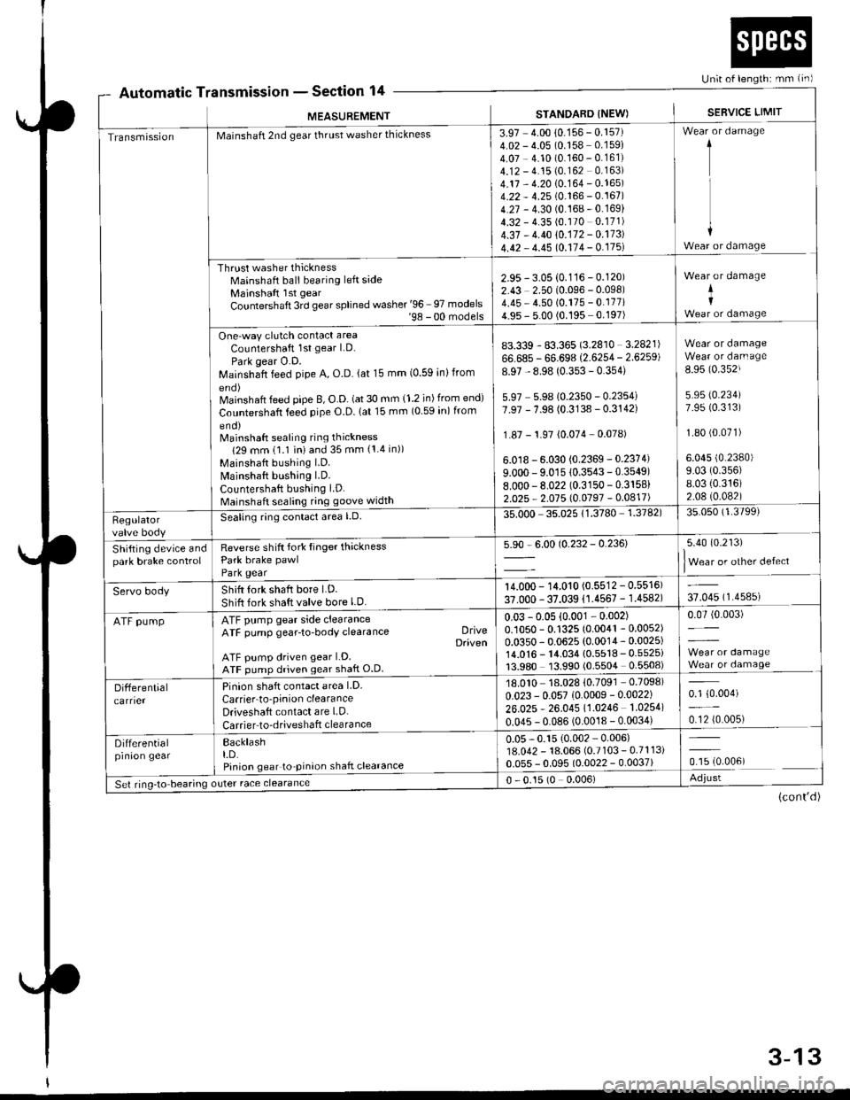
Automatic TnsmtsstonSection 14Un;t of length: mm {in)
r
MEASUREMENT
a
STANDARD INEW)SEBVICE LIMIT
TransmissionMainshaft 2nd gear thrust washer thickness
Thrust washer thicknessMainshaft ball bearing left sideMainshaft lst gear
Countershaft 3rd gear splined washer '96 97 models'98 - 00 models
One-way clutch contact area
Countershaft 1st gear LD.
Park gear O.D.Mainshaft feed pipe A, O.D. (at 15 mm (0.59 inlfrom
Mainshaft feed pipe B, O.D. (at 30 mm {1.2 in) from end)
Countershaft feed pipe O.D. lat 15 mm (0 59 in) from
eno)Mainshaft sealing ring thickness
129 mm 11.1 iniand 35 mm {1.4 in))
Mainshaft bushing l.D.
Mainshaft bushing LD.
Countershaft bushing LD.Mainshaft sealing ring goove width
3.97 4.00 10.156 - 0.157)4.02 - 4.05 (0.158 0.159)
4.07 - 4.10 (0.160 - 0.161)4.12 - 4.15 (0.162 0.163)
4.17 - 4.20 10.164 - 0.165)4.22 - 4.25 (0.166 - 0.167)4.27 - 4.30 (0.168-0.169)
4.32 - 4.35 (0.170 0.171)
4.37 - 4.40 10.172 - 0.173)
4.42 - 4.45 10.114 - 0.175l
1
I
+Wear or damage
2.95 - 3.05 {0.116 - 0.120)2.43 2.50 (0.096 - 0.098)4.45 - 4.50 (0.175 - 0.177i4.95 - 5.00 (0.195 0.197)
Wear or damage
+I
83.339 - 83.365 (3.2810 3.2821)
66.685 - 66.698 (2.6254 - 2.6259)
8.97 - 8.98 (0.353 - 0.354)
5.97 5.9810.2350 - 0.2354i7.97 - 7.98 (0.3138 - 0.3142)
1.87 - 1.97 {0.074 0.078)
6.0 r8 - 6.030 {0.2369 - 0.2374)
9.000 - 9.01s 10.3543-0.3549)8.000-8.022 (0.3150 - 0.3158)
2.025 - 2.015 l0.0197 -0.0417)
Wear or damageWear or darn age
8.95 (0.352J
5.95 (0.234)
7.95 (0.313)
1.80 (0.071)
6.045 (0.2380)
9.03 (0.356)
8.03 {0.316)2.08 (0.082)
Regulatorvalve body
Seating ring conlact area l.D.35.000 35.02511.3780 1.3782)35.050 (1.3799)
Shifting device andpark brake controlReverse shift fork Iinger thicknessPark brake pawl
Park gear
5.90 - 6.00 (0.232 - 0.236)5.40 (0.213)
lWear or other defect
Servo bodyShift fork shaft bore LD.
Shift fork shaft valve bore l.D.
14.000 - 14.010 (0.5512 - 0.5516)
37.000 - 37.039 (1.4567 - 1.4582)37.045 (1.4585)
ATF pumpATF pump gear side clearanceATF pump gear-to-body clearance DriveDaiven
ATF pump driven gear LD.ATF pump driven gear shaft O.D
0.03 -0.05 {0.001 - 0.002)0.1050 - 0.1325 (0.0041 - 0.0052)
0.0350 - 0.0625 (0.0014 - 0.0025)14.0'�|6 - 14.034 {0.5518 - 0.5525i13.980 13.990 (0.5504 0.5508)
0.07 (0.003)
Differentialcarrier
Pinion shaft contact area LD.
Carrier to'pinion clearanceDriveshaft contact are LD.
Carrier to-driveshaft clearance
18.010 18.028 {0.7091 0.7098)
0.023 - 0.057 (0.0009 -0.0022)
26.025 * 26.045 11.0246 1.0254)
0.045 - 0.086 (0.0018 - 0.0034)
0.1 {0.004)
0.12 {0.005)
Differentialprnron gearBacklasht.D.Pinion gear to-pinion shaft clearance
0.05 - 0.15 {0.002 - 0.006)18.042 - 18.066 (0.7103 - 0.7113i0.055 - 0.095 (0.0022 - 0.0037)ffi.oour
Set ring-to bearing outer race clearance0 - 0.15 (0 0.006)Adjust
(cont'd)
3-13
Page 124 of 2189
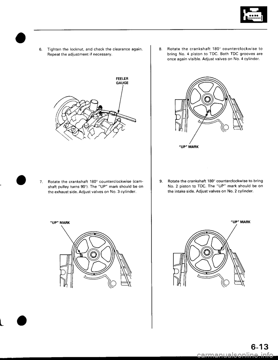
6. Tighten the locknut, and check the clearance again.
Repeat the adjustment if necessary.
GAUGE
7.Rotate the crankshaft 180' counterclockwise (cam-
shaft oullev turns 90'1. The "UP" mark should be on
the exhaust side. Adjust valves on No. 3 cylinder.
"UP- MARK
t
8. Rotate the crankshaft '180' counterclockwise to
bring No.4 piston to TDC. Both TDC grooves are
once again visible. Adjust valves on No. 4 cylinder.
Rotate the crankshaft 180'counterclockwise to bring
No. 2 piston to TDC. The "UP" mark should be on
the intake side. Adjust valves on No. 2 cylinder.
-UP'MARK
6-13
Page 129 of 2189
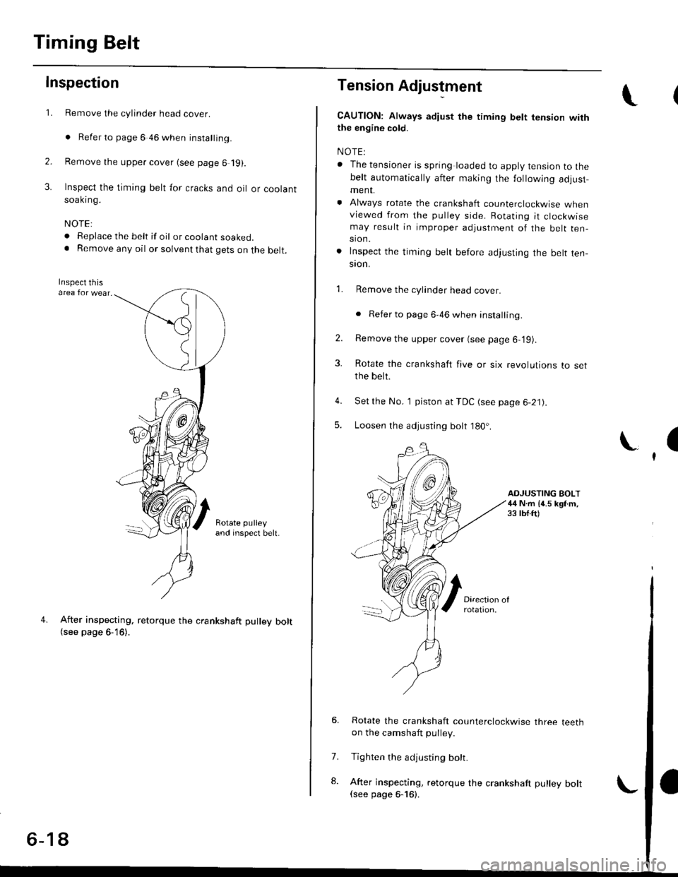
Timing Belt
Inspection
1.
2.
3.
Remove the cylinder head cover.
. Refer to page 6 46 when installing.
Remove the upper cover (see page 6 19).
Inspect the timing belt for cracks and oil or coolantsoakrng.
NOTE:
. Replace the belt if oil or coolant soaKeo.. Remove any oil or solvent that gets on the belt.
Rotate pulleyand inspect belt.
After inspecting, retorque the crankshaft pullev bolt{see page 6- 16).
o- I6
Tension Adjustment
CAUTION: lt*ays aa;j"t the timing bett rension withthe engine cold.
NOTE:
. The tensioner is spring loaded to apply tension to thebelt automatically after making the following adjustment.
. Always rotate the crankshaft counterclockwise whenviewed from the pulley side. Rotating it clockwisemay result in improper adjustment of the belt ten-sion.
. lnspect the timing belt before adjusting the belt ten-ston.
1.Remove the cylinder head cover.
. Refer to page 6,46 when installing.
Remove the upper cover (see page 6,'19).
Rotate the crankshaft five or six revolutions to setthe belt.
Set the No. 'l piston at TDC (see page 6-21).
Loosen the adjusting bolt 180'.
2.
3.
4.
5.
\I
ADJUSTING BOLT44 N.m {4.5 kgt m,33 rbf.ft)
7.
8.
Rotate the crankshaft counterclockwise three teethon the camshaft pulley.
Tighten the adjusting bolt.
After inspecting, retorque the crankshaft pulley bolt(see page 6-16).
Page 132 of 2189
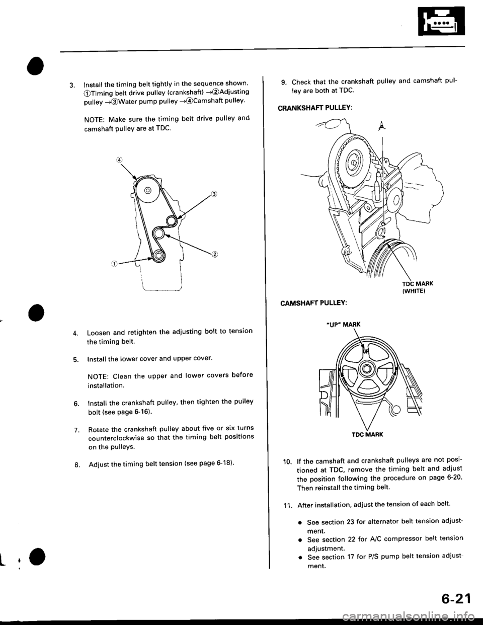
3. Install the timing belt tightly in the sequence shown'
OTiming belt drive pullev (crankshaft) )@Adjusting
pulley -towater pump pulley J@Camshatt pulley'
NOTE: Make sure the timing belt drive pulley and
camshaft PulleY are at TDC
7.
Loosen and retighten the adiusting bolt to tension
the timing belt.
lnstall the lower cover and upper cover.
NOTE: Clean the upper and lower covers before
installation.
lnstall the crankshaft pulley, then tighten the pulley
bolt (see page &16)
Rotate the crankshaft pulley about five or six turns
counterclockwise so that the timing belt positions
on the Pulleys.
Adjust the timing belt tension (see page 6-18).8.
L
9. Check that the crankshaft pulley and camshaft pul-
ley are both at TDC.
CRANKSHAFT PULLEY:
CAMSHAFT PULLEY:
lf the camshaft and crankshaft pulleys are not posi-
tioned at TDC, remove the timing belt and adjust
the position following the procedure on page 6-20'
Then reinstall the timing belt.
After installation, adjust the tension of each belt
. See section 23 for alternator belt tension adjust-
ment.
a See section 22 tot NC compressor belt tension
adjustment.
. See section 17 for P/S pump belt tension adjust
ment,
(wHrTE)
"UP" MARK
TDC MARK
11.
6-21
Page 168 of 2189
Valve Clearance
I
I
I
Adjustment {cont'd)
5. Tighten the locknut and recheck clearance.Repeat adjustment if necessary.
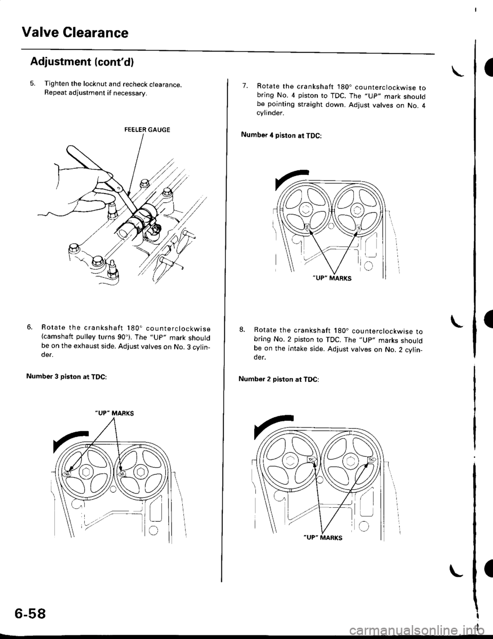
Rotate the crankshaft 180. counterclockwise(camshaft pulley turns 90'). The "Up" mark shouldbe on the exhaust side. Adjust valves on No. 3 cylin-der.
Number 3 piston at TDC:
FE€LER GAUGE
"UP- MARKS
6-58
7. Rotate the crankshaft '180. counterclockwise tobring No. 4 piston to TDC. The ,,Up,. mark shouldbe pointing straight down. Adjust valves on No. 4cylinder.
Number 4 piston at TDC:
8, Rotate the crankshaft 180. counterclockwise tobring No. 2 piston to TDC. The "Up., marks shouldbe on the intake side. Adjust valves on No. 2 cylin_der.
Number 2 piston at TDC:
L
Page 171 of 2189
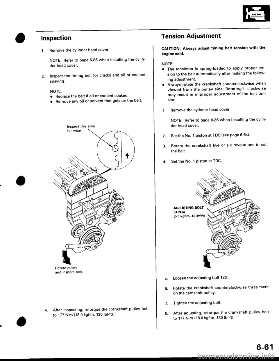
Inspection
Remove the cylinder head cover.
NOTE: Refer to page 6-86 when installing the cylin-
der head cover.
Inspect the timing belt for cracks and oil or coolant
soakrng.
NOTE:
. Replace the belt if oil or coola nt soaked.
. Remove any oil or solvent that gets on the belt'
I
Rotate PUlleYand inspect belt-
After inspecting, retorque the crankshaft pul
to 177 N.m (18.0 kgf'm, 130 lbf'ft)
'L
lnspect thrs area
Tension Adiustment
CAUTION: Always adiust timing belt tension with the
engine cold.
NOTE:
. The tensioner is spring-loaded to apply proper ten
sion to the belt automatically after making the follow-
ing adjustment.
. Always rotate the crankshaft counterclockwise when
viewed from the pulley side. Rotating it clockw'se
may result in improper adjustment of the belt ten-
sion.
1, Remove the cylinder head cover.
NOTE; Refer to page 6-86 when installing the cylin-
der head cover.
2. Set the No. 1 piston at TDC (see page 6-64)
3. Rotate the crankshaft live or six revolutions to set
the belt.
4. Set the No. 1 Piston at TDC
ADJUSTING BOLT
54 N.m(5.5 kgt.m, a0 lbtftl
5.
7.
8.
Loosen the adjusting bolt 180'.
Rotate the crankshaft counterclockwise three teeth
on the camshaft PulleY.
Tighten the adjusting bolt.
After adjusting, retorque the crankshaft pulley bolt
to 177 N.m (18.0 kgf'm, 130 lbnft)
ley bolt
6-61
Page 174 of 2189
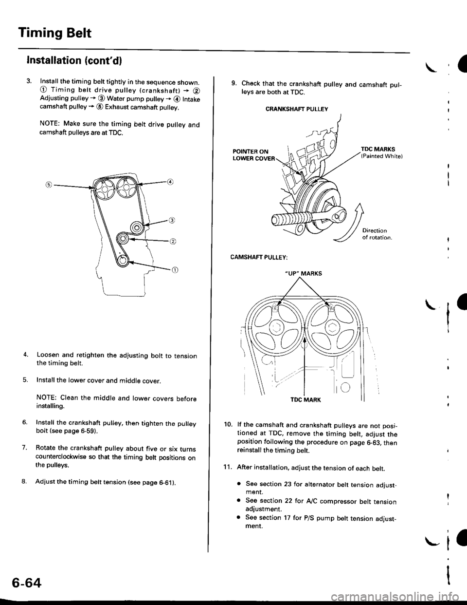
Timing Belt
lnstallation (cont'dl
3. Install the timing belt tightly in the sequence shown.
@ Timing belt drive pulley (crankshaft) + @Adjusting pulley * @ Water pump pu ey + @ Intakecamshaft pulley + @ Exhaust camshaft pulley,
NOTE: Make sure the timing belt drive pulley andcamshaft pullevs are at TDC,
Loosen and retighten the adjusting bolt to tensionthe timing belt.
Install the lower cover and middle cover.
NOTE: Clean the middle and lower covers beforeinstalling.
Install the crankshaft pulley, then tighten the pulleybolt (see page 459).
Rotate the crankshaft pulley about five or six turnscounterclockwise so that the timing belt positions onthe pulleys.
Adjust the timing belt tension (see page A611.
7.
6-64
a
9. Check that the crankshaft pulley and camshaft pul-leys are both at TDC.
CRANKSHAFT PULLEY
CAMSHAFT PULLEY:
lf the camshaft and crankshaft pulleys are not posi-tioned at TDC, remove the timing belt, adjust theposition following the procedure on page &63, thenreinstall the timing belt.
After installation, adjust the tension of each belt.
. See section 23 for alternator belt tension adjust-ment.
. See section 22lor NC compressor belt tensionadiustment,
. See section 17 for P/S pump belt tension adjust-ment.
'l
10.
11.
I
"UP" MARKS
Page 206 of 2189
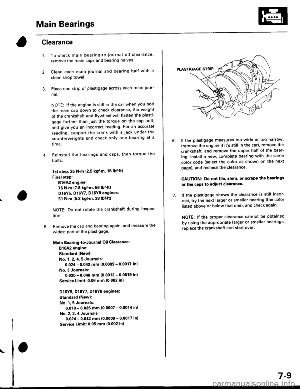
Main Bearings
4.
Glearance
1.To check main bearing-to-journal oil clearance.
remove the main caps and bearing halves.
Clean each main journal and bearing half with a
clean shop towel.
Place one strip of plastigage across each main jour-
na l.
NOTE: lf the engine is still in the car when you bolt
the main cap down to check clearance, the weight
of the crankshaft and flvwheel will flaften the plasti-
gage further than just the torque on the cap bolt.
and give you an incorrect reading. For an accurate
reading, support the crank with a jack under the
counterweights and check only one bearing at a
time,
Reinstall the bearings and caps, then torque the
bolts.
lst step: 25 N'm (2.5 kgl'm. 18 lbf'ft)
FinalsteD:
B16A2 engine:
76 N.m (7.8 kgf.m, 56 lbf'ft)
D16Y5, Dl6Y7, D16Y8 engines:
51 N.m (5.2 kgf'm, 38 lbf'ft)
NOTE: Do not rotate the crankshaft during inspec-
tron.
Remove the cap and bearing again, and measure the
widest part ot the plastigage.
Main Boaring-toJournal Oil Clearance:
816A2 engine:
Standald {New}:
No. l, 2, 4, 5 Journals:
O.O2,l - 0.042 mm 10'00(B - 0.0017 in)
No. 3 Journals:
0.030 - 0.048 mm {0'0012 - 0'0019 in)
Servico Limit: 0.06 mm {0.002 in,
Dl6Y5, Dl6
r, Dl6Y8 engines:
Standard (Nsw):
No. 1,5 Journals:
0.018 - 0.035 mm {0.0007 - 0'001'[ in)
No. 2. 3, 4 Journals:
0.02,1 - 0.0,(2 mm {0'0009 - 0.0017 in}
Service Limit: 0.05 mm (0.002 in)
\
7-9
7.
lf the plastigage measures too wide or too narrow,
(remove the engine if it's still in the car), remove the
crankshaft, and remove the upper half of the bear-
ing. Install a new. complete bearing with the same
color code {select the color as shown on the next
page), and rechsck the clearance.
CAUTION: Do nol fil€, shim, or scrape the bearings
or tho cap3 to adiust cleatanc€.
lf the plastigage shows the clearance is still incor-
rect, try the next larger or smaller bearing (the color
listed above or below that one), and check again
NOTE: lf the proper clearance cannot be obtained
by using the appropriate larger or smaller bearings,
replace the crankshaft and start over.