G551 HONDA CIVIC 1999 6.G Workshop Manual
[x] Cancel search | Manufacturer: HONDA, Model Year: 1999, Model line: CIVIC, Model: HONDA CIVIC 1999 6.GPages: 2189, PDF Size: 69.39 MB
Page 1483 of 2189
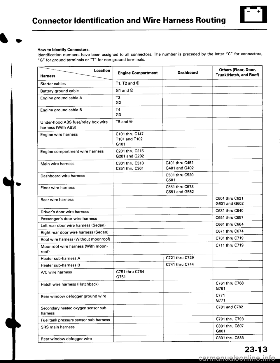
Connector ldentification and Wire Harness Routing
D
How to ldentify Connectors:
ldentification numbers have been assigned to all connectors. The number is preceded by the letter "C" for connectors,"G" for ground terminals or "T" for non-ground terminals.
Location
HarnessEngine CompartmentDashboardOthers {Floor, Door,
Trunk/Hatch, and Rootl
Starter cablesT1, T2 and @
Battery ground cableG1 and O
Engine ground cable AT3
G2
Engine ground cable BT4
Under-hood ABS fuse/relay box wire
harness (With ABS)
t5 ano (9
Engine wire harnessCl01 thru C147
T101 and T102
G101
Engine compartmenl ware harnessC201 thru C215
G201 and G202
Main wire harnessC301 thru C310
C351 thru C361
C401 thru C452
G401 and G402
Dashboard wire harnessC501 thru C520
G501
FIoor wire harnessC551 thru C573
G551 and G552
Rear wire harnessC601 thru C62l
G601 and G602
Driver's door wire harnessC631 thru C640
Passenger's door wire harnessC651 thru C657
Left rear door wire harness (Sedan)C661 thru C664
Right rear door wire harness (Sedan)C671 thru C674
Roof wire harness (Without moonroof)C701 thru C719
Moonroof wire harness {With moon-
roof)
C7l'l thru C719
Heater sub-harness AC721 thru C729
Heater sub-harness BC7 41 thtu C7 44
Ay'C wire harnessC751 thru C754
G751
Hatch wire harness (Hatchback)C761 thru C768
Rear window defogger grgund wirec771
G171
Secondary heated orygen sensor sub-
narness
C781 and C782
Fuel tank pressure sensor sub-harnessC791 thru C793
SRS main harnessC801 thru C807
G801
Rear window defogger wireC831 thru C833
Page 1510 of 2189
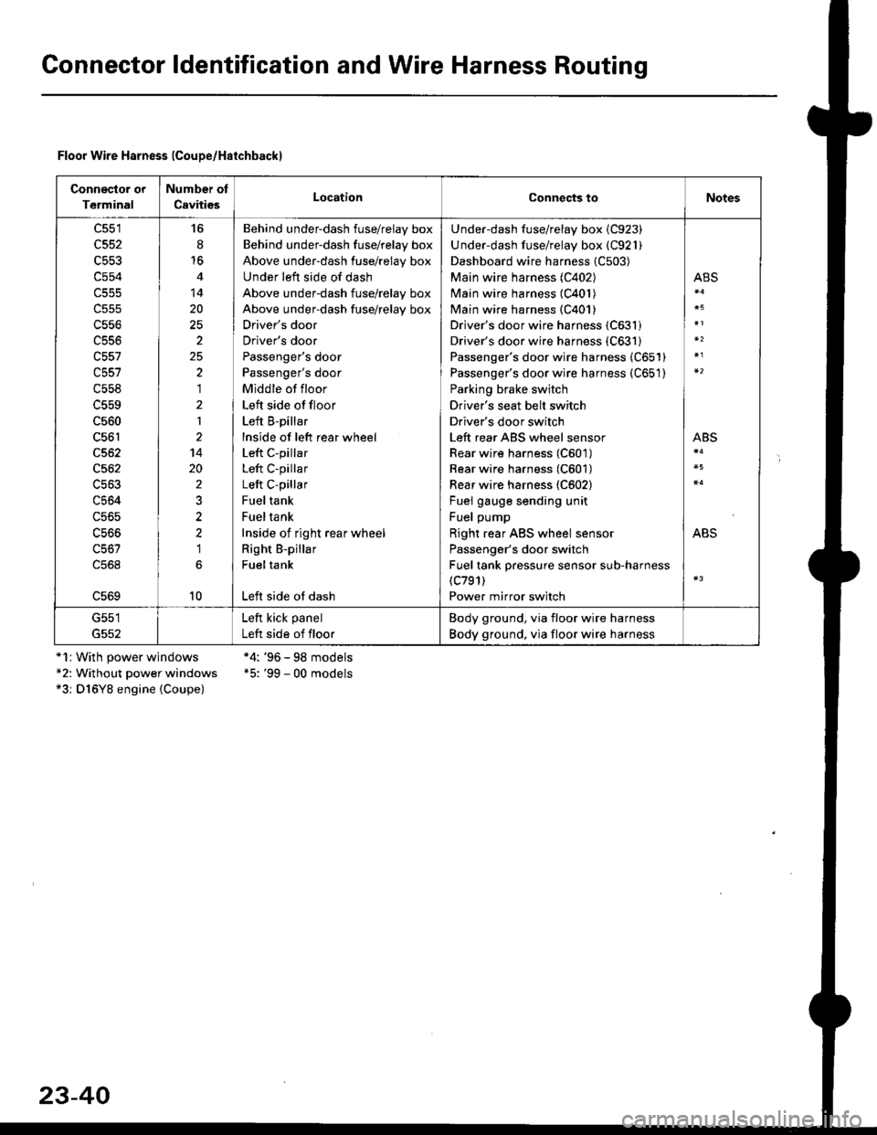
Gonnector ldentification and Wire Harness Routing
Floor Wire Harness lCoupe/Haichbackl
Connsclor or
Terminal
Number of
CavitiesLocationConnects toNotes
c551
c552
c553
c554
c556
c556
c557
c558
c560
c561
c562
c564
c56s
16
8'16
14
20
2
25,)
,I
2
1
14
20
2
2?
1
10
Behind underdash fuse/relay box
Behind under-dash fuse/relay box
Above under-dash fuse/relay box
Under left side of dash
Above under-dash fuse/relay box
Above under-dash fuse/relay box
Driver's door
Driver's door
Passenger's door
Passenger's door
Middle of floor
Left side offloor
Left B-pillar
lnside of left rear wheel
Left c-pillar
Left C-pillar
Left C-pillar
Fueltank
Fueltank
Inside of right rear wheel
Right B-pillar
Fueltank
Left side ot dash
Under-dash fuse/relay box {C923)
Under-dash fuse/relay box (C921)
Dashboard wire harness {C503)
Main wire harness (C402)
Main wire harness (C401)
Main wire harness {C401)
Driver's door wire harness (C631)
Driver's door wire harness (C631)
Passenger's door wire harness (C651)
Passenger's door wire harness (C651)
Parking brake switch
Driver's seat belt switch
Driver's door switch
Left rear ABS wheel sensor
Rear wire harness (C601)
Rear wire harness (C601)
Rear wire harness {C602}
Fuel gauge sending unit
Fuel pump
Right rear ABS wheel sensor
Passenger's door switch
Fuel tank pressure sensor sub-harness(c791)
Power mirror switch
ABS
ABS
ABS
G551
G552
Left kick panel
Left side of floor
Body ground, via floor wire harness
Body ground. via floor wire harness
*1r With power windows*2: Without power windows*3: D16Y8 engine {Coupe)
*4: '96 - 98 models*5: '99 - 00 models
23-40
Page 1514 of 2189
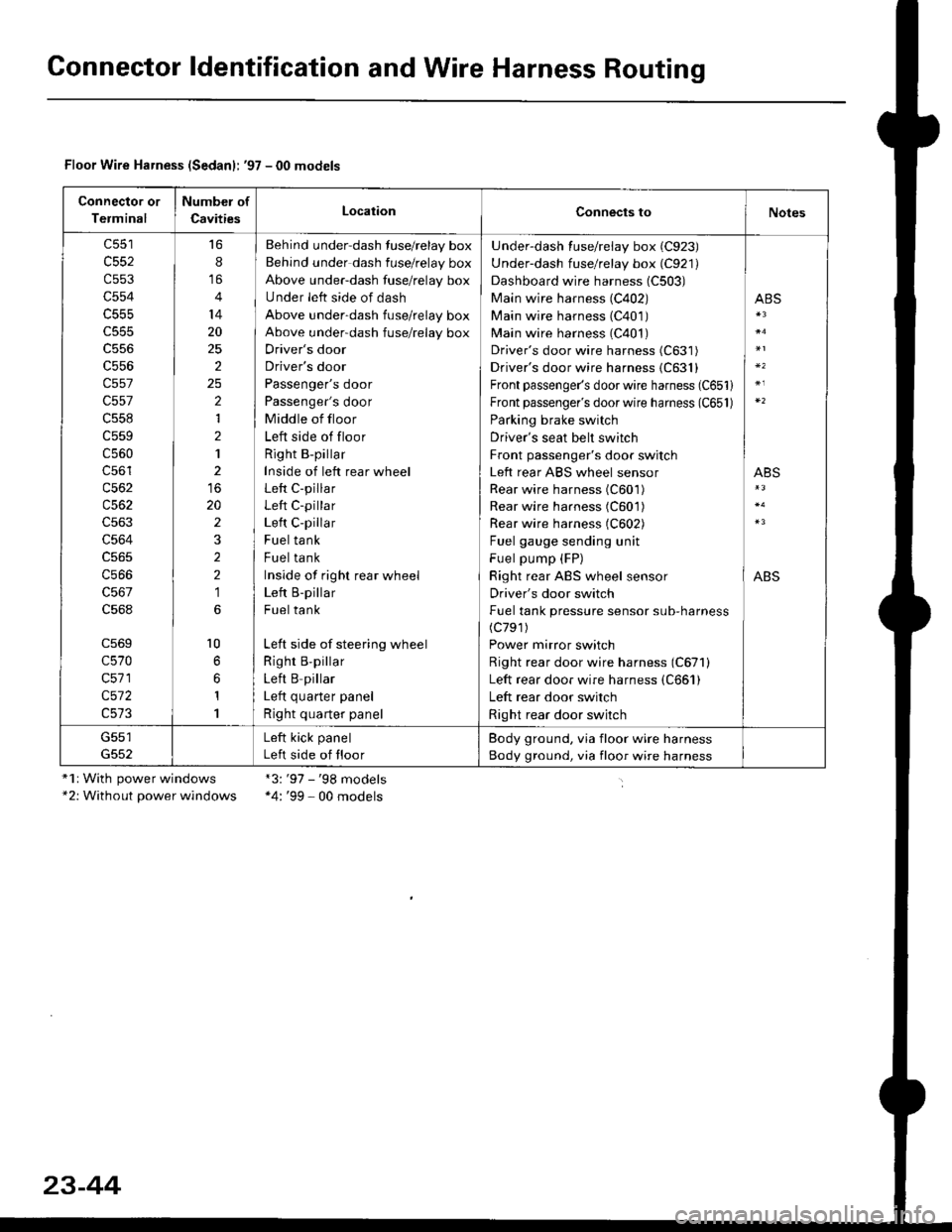
Gonnector ldentification and Wire Harness Routing
Floor Wire Harness (Sedanl: '97 - 00 models
Connector or
Terminal
Number of
CavitiesLocationConnects toNotes
c552
c553
c554
c555
c556
c557
c557
c558
c559
c560
c56'l
c562
c563
c564
c566
c568
c569
c570
c571
c572
16
8
14
20
25
2
2
1
2
1
20
2
2
2
1
l0
1
1
Behind under-dash fuse/relay box
Behind under dash fuse/relay box
Above under-dash fuse/relay box
Under left side of dash
Above under-dash fuse/relay box
Above under-dash fuse/relay box
Driver's door
Driver's door
Passenger's door
Passenger's door
Middle of floor
Left side of floor
Right B-pillar
Inside of left rear wheel
Left C-pillar
Left C-pillar
Left C-pillar
Fuel tank
Fuel tank
Inside of righr rear wheel
Left B-pillar
Fuel tank
Left side of steering wheel
Righr B,pillar
Left B pillar
I ofr ^,,.riar ^.^al
Right quarter panel
Under-dash fuse/relay box (C923)
Under-dash fuse/relay box (C921)
Dashboard wire harness (C503)
Main wire harness (C402)
Main wire harness (C401)
Main wire harness (C401)
Driver's door wire harness (C631)
Driver's door wire harness {C631}
Front passenger's door wire harness (C651)
Front passenger's door wire harness (C651)
Parking brake switch
Driver's seat belt switch
Front passenger's door switch
Left rear ABS wheel sensor
Rear wire harness (C601)
Rear wire harness (C601)
Rear wire harness (C602)
Fuel gauge sending unit
Fuel pump (FP)
Right rear ABS wheel sensor
Driver's door switch
Fuel tank pressure sensor sub-harness(c791)
Power mirror switch
Right rear door wire harness (C671)
Left rear door wire harness (C661)
Left rear door switch
Right rear door switch
ABS
ABS
ABS
G551Left kick panel
Left side of floor
Body ground, via floor wire harness
Body ground, via floor wire harness
"1r With power windows*2: Without power windows
*3:'97 - '98 models*4: '99 - 00 models
23-44
Page 1552 of 2189
![HONDA CIVIC 1999 6.G Workshop Manual Ground Distribution
Circuit ldentification (contdl
99-00 models:(Wilholl ABS)
r1BL( -< 6 | c40. tFror oaoe 23-BC. II
L
E
UNDEF.H@DFUSF]RELAY BOX
_::I
A,/I gefi posilion swilchELD unil
Servi@ check](/img/13/6068/w960_6068-1551.png "HONDA CIVIC 1999 6.G Workshop Manual Ground Distribution
Circuit ldentification (contdl
99-00 models:(Wilholl ABS)
r1BL( -< 6 | c40. tFror oaoe 23-BC. II
L
E
UNDEF.H@DFUSF]RELAY BOX
_::I
A,/I gefi posilion swilchELD unil
Servi@ check")
Ground Distribution
Circuit ldentification (cont'dl
'99-00 models:(Wilholl ABS)
r'1BL( -< 6 | c40. tFror oaoe 23-BC. II
L
E
UNDEF.H@DFUSF]RELAY BOX
_::I
A,/I gefi posilion swilchELD unil
Servi@ check connector
BL-_14BL- rl--{ry--Browe,mororreray
L4 ,r^ -.;--a-r,* -11-51 BLK - Hearer conrror o6nt n"*-fi-+aLx-lfuBLK- Hearer conrror panel
eLx -iff BLK - ff;?,m",:[:' "n'
or*
ABS glmp motor
_trl
G501
Pos€r door lock cortaol unitDivers door lock aclualorDriver's door lock switchLefl miror delogger
BLK --.+t _
F J Power wndos man swdch
-. Dive/s Fo*gr window motor
TBLK -.1 F--{ BLK - Fighr.niror detogger
tr
tr
E : Healer sub-haness A
El : Healer sub'harress B
: Floor wire hamess
: Drve/sdoorwife haness
-
|,-"*T-"^tl I
vl-L"."
G551
ort,
El ' Main *it" hanes
E : Dashboafd wirc harness
23-82
@ Passenger's doof w're hamess
Page 1677 of 2189
![HONDA CIVIC 1999 6.G Workshop Manual Circuit Diagram (Without Defogger)
UNDER.HOOD FUSE]FELAY BOX
eo;T f-*---;,;r j-_l 6\
OF+-*.v-f r--;. -"j-a,_cy
GN TIONSWITCH
UNDER DASHFUSEIRELAYBOX
BLK]YEL
) I dRGHT LEFTd I dFlGHrf- -- ---\,](/img/13/6068/w960_6068-1676.png "HONDA CIVIC 1999 6.G Workshop Manual Circuit Diagram (Without Defogger)
UNDER.HOOD FUSE]FELAY BOX
eo;T f-*---;,;r j-_l 6\
OF+-*.v-f r--;. -\"j-a,_cy
GN TIONSWITCH
UNDER DASHFUSEIRELAYBOX
BLK]YEL
) I dRGHT LEFTd I dFlGHrf- -- ---\,")
Circuit Diagram (Without Defogger)
UNDER.HOOD FUSE]FELAY BOX
eo;T f-*---;',;r j-_l 6\
OF+-*'.v-f r'--;.' -"j-'a,_cy'
GN TIONSWITCH
UNDER DASHFUSEIRELAYBOX
BLK]YEL
) I dRGHT LEFTd I dFlGHr'f- -- ---\,
TT
I
I.t.olo
G551
23-207
(}-
Page 1678 of 2189
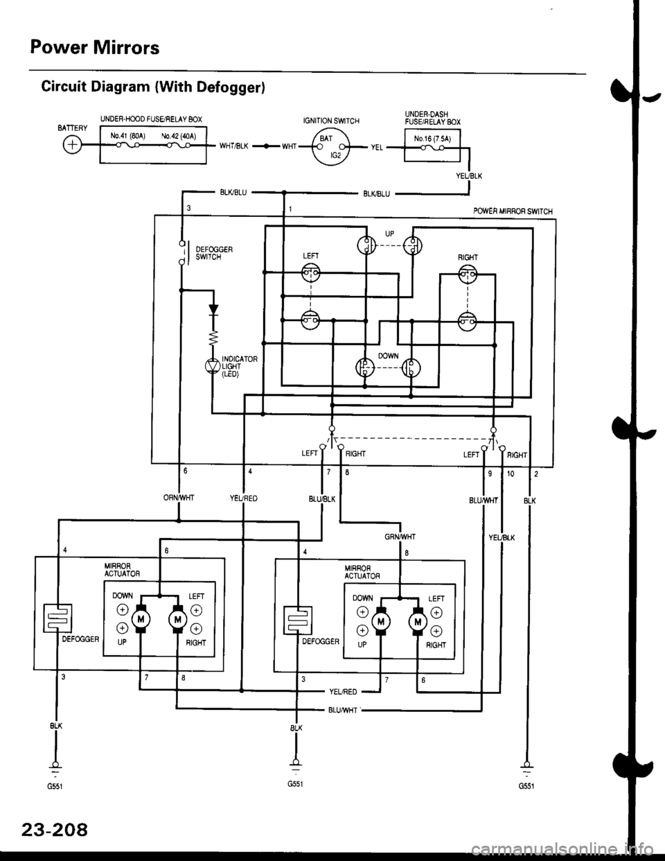
Power Mirrors
UNDER.OASHFUSE/FELAY BOX
Circuit Diagram {With Defogger)
BLK
G551
8LK
I
G551
YEURED
BLUMHT
8LK
II
-f,:
G551
23-208
UNDER-HOOD FUSE/RELAY BOX
/lr,---------- ---zlr
I'BLUELKl'YEUBEO
6
ORN/WHT
Page 1679 of 2189
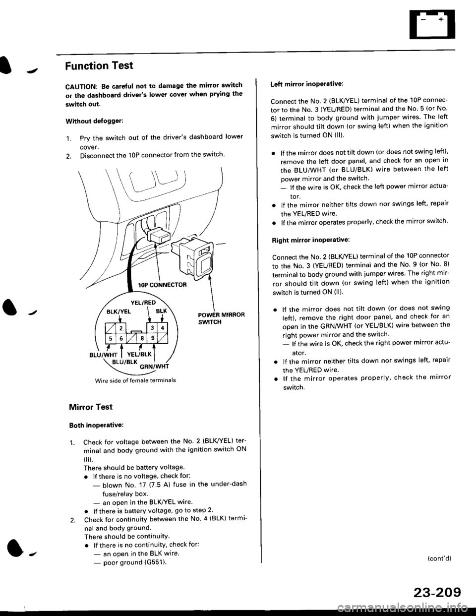
Function Test
CAUTION: Be careful not to damage the mirror switch
or the dashboard drivel's lower covel when prying the
swhch out.
Withoui defogger:
1. Pry the switch out of the driver's dashboard lower
cover.
2. Disconnect the 10P connector from the switch.
lOP CONNECTOR
BLU/WHT
YEL/RED
BLK/YELBLK
4
568
YEL/BLK
POWER MIRRORswtTcH
\:/"*jgil*-(
Wire side of female termanals
Mirror Test
Both inoperative:
1. check for voltage between the No. 2 (BLVYEL) ter
minal and body ground with the ignition switch ON
0 r).
There should be batterY voltage
. If there is no voltage, check for:
- blown No. 17 (7 5 A) fuse in the under-dash
tuse/relay box- an open in the BLK'/YEL wire.
o lf there is battery voltage, go to step 2.
2. Check for continuity between the No 4 (BLK) termi-
nal and body ground.
There should be continuity.
. lf there is no continuity, check for:
- an open in the BLK wire.
- poor ground (G551).
Left mirror inoporalive:
connect the No. 2 {BLK/YEL) terminal of the 10P connec-
tor to the No. 3 (YEURED) terminal and the No 5 (or No
6) terminal to body ground with jumper wires The left
mirror should tilt down (or swing left) when the ignition
switch is turned ON (ll)
. lf the mirror does not tilt down (or does not swing left),
remove the left door panel. and check for an open in
the BLU/WHT (or BLU/BLK) wire between the left
power mirror and the switch
- lf the wire is OK. check the left power mirror actua-
tor.
lf the mirror neither tilts down nor swings left. repair
the YEURED wire.
lf the mirror operates properly, check the mirror switch'
Right mirror inoperative:
Connect the No. 2 (BLK /EL) terminal of the 10P connector
to the No. 3 (YEURED) terminal and the No. 9 (or No 8)
terminal to body ground with jumper wires The right mir-
ror should tilt down (or swing left) when the ignition
switch is turned ON (ll).
. lf the mirror does not tilt down (or does not swlng
left), remove the right door panel. and check for an
open in the GRN/WHT (or YEUBLK) wire between the
right power mirror and the switch.
- lf the wire is OK, check the right power marror actu-
ator.
. lf the mirror neither tilts down nor swings left. repair
the YEURED wire
. lf the mirror operates properly, check the mirror
switch.
(cont'd)
23-209
Page 1680 of 2189
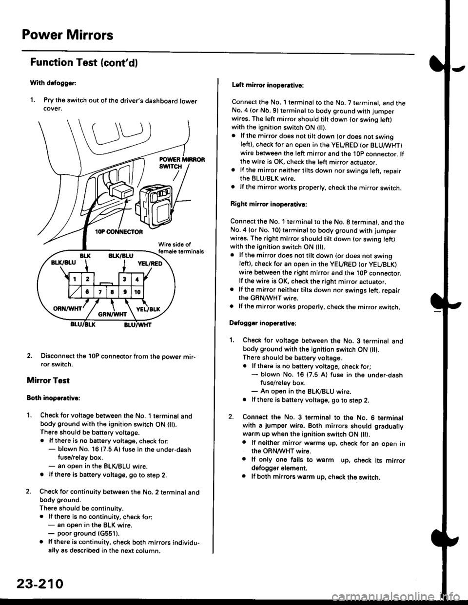
Power Mirrors
Funstion Test (cont'dl
With dcfoggcr:
1. Pry the switch out ot the driver's dashboard lowercover.
2. Disconnect the 10P coonector from the oower mir-ror switch.
Mirror Test
Bolh inoparrtiv.:
1. Check for voltage between the No. 1 terminal andbody ground with the ignition switch ON flt).There should be battery voltage.. lf there is no battery voltage, check to.:- blown No. 16 (7.5 A) fuse in the under-dash
tuse/relay box.- an open in the BLVBLU wrre.
! lf thero is banery voltage, go to step 2.
2. Check for continuity b€tween the No. 2 terminal andbody ground.
There should be continuitv.. ll there is no continuity, check tor:- an open in the BLK wire.- poor ground (G5511.
. lJthere is continuity. check both mirrors individu-ally 8s described in the next column,
23-210
Laft mirror inopcrativ!:
Connect the No. 1 terminal to the No. 7 terminal. and theNo. 4 (or Nb.9) terminalto body ground with jumper
wires. The left mirror should tilt down (or swing left)with the ignition switch ON (ll).
. lf the mirror does not tilt down (o. does not swinglett), check for an open in the YEURED (or BLUMHT)wire between the left mirror and the 10p connector. lfthe wire is OK, check the left mirror actuator.a lf the mirror neither tilts down nor swings left, repairthe BLU/BLK wire.
t lf the mirror works properly, check the mirror switch.
Right mi.ror inopcrativc:
Connect the No. 1 terminal to the No. 8 terminal, and theNo.4 (or No. 10) terminalto body ground with l'umperwi.es. The right mirror should tilt down (or swing lett)with the ignition switch ON (ll).
. lf the mirror does not tilt down {or does not swingleft), check for an open in the YEURED {or YEUBLK)
wire between the right mirror and the l0P connector.lf the wire is OK, check the right mirror actuator,. lf the mirror neither tilts down nor swings left, repairthe GRN/WHT wire.o lf the mirror works properly. check the mirro. switch,
Dafoggcr inoperEtivo:
1. Check for voltage between the No. 3 terminal andbody ground with the ignition switch ON (||).
There should be battery voltage.a lf there is no battery voltage, check for;- blown No. 16 (7.5 A) luse in the under-dash
fuse/rel8y box,- An open in the BLK,iBLU wire.. It there is battery voltage, go to step 2.
2. Connsct the No. 3 tsrminal to the No. 6 terminalwith a iumpsr wire. Both mirrors should gradually
warm up when the ignition switch ON flt).a lf neither mirror warms up, check for an open inthe ORN/WHT wire.. It only on€ lails to warm up, check its mirrordsfogger elem6nt.. lf both mirrors warm up, check ths switch.
Page 1691 of 2189
![HONDA CIVIC 1999 6.G Workshop Manual IJCircuit Diagram (96-98 Coupe/Hatchbackl
WHT]BLK +WHT
WHTtsLU
l/
UNDER.HOOD FUSE/RELAY BOX
BLK
G551PASSENGEBSWNDOW MOIOR
G401G()2
23-221
l,](/img/13/6068/w960_6068-1690.png "HONDA CIVIC 1999 6.G Workshop Manual IJCircuit Diagram (96-98 Coupe/Hatchbackl
WHT]BLK +WHT
WHTtsLU
l/
UNDER.HOOD FUSE/RELAY BOX
BLK
G551PASSENGEBSWNDOW MOIOR
G401G()2
23-221
l,")
IJCircuit Diagram ('96-98 Coupe/Hatchbackl
WHT]BLK +WHT
WHTtsLU
l/
UNDER.HOOD FUSE/RELAY BOX
BLK
G551PASSENGEB'SWNDOW MOIOR
G401G()2
23-221
l,
Page 1692 of 2189
![HONDA CIVIC 1999 6.G Workshop Manual Power Windows
Circuit Diagram (96-98 Sedan)
UNDER HOOD FUSE/RELAY BOX
I.iASTER SWITCH
UNDER.DASH FUSUBELAYEOX
BLU/ELK
B3
3 I BIGHT BEAR
l$,]ilP3,y
FBONTPASSENGERSWINDOWswtTcH
BLK
t
G551LEFT HEAF WI](/img/13/6068/w960_6068-1691.png "HONDA CIVIC 1999 6.G Workshop Manual Power Windows
Circuit Diagram (96-98 Sedan)
UNDER HOOD FUSE/RELAY BOX
I.iASTER SWITCH
UNDER.DASH FUSUBELAYEOX
BLU/ELK
B3
3 I BIGHT BEAR
l$,]ilP3,y
FBONTPASSENGERSWINDOWswtTcH
BLK
t
G551LEFT HEAF WI")
Power Windows
Circuit Diagram ('96-98 Sedan)
UNDER HOOD FUSE/RELAY BOX
I.iASTER SWITCH
UNDER.DASH FUSUBELAYEOX
BLU/ELK
B3
3 I BIGHT BEAR
l$',]ilP3,y
FBONTPASSENGER'SWINDOWswtTcH
BLK
t
G551LEFT HEAF WINDOWMOTOR
23-222
R GNT REAR WINDOWMOTOR
BLK
I
G551FRONT PASSENGER'SWINOOW MOTOR
c401G402