Mile HONDA CIVIC 1999 6.G Workshop Manual
[x] Cancel search | Manufacturer: HONDA, Model Year: 1999, Model line: CIVIC, Model: HONDA CIVIC 1999 6.GPages: 2189, PDF Size: 69.39 MB
Page 130 of 2189
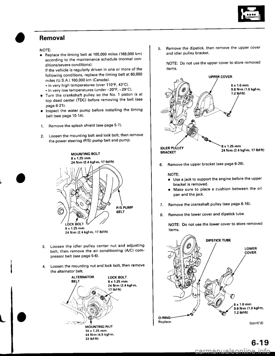
Removal
NOTE:
. Replace the timing belt at 105,000 miles (168.000 km)
according to the maintenance schedule (normal con-
ditions/severe conditions).
lf the vehicle is regularly driven in one or more of the
followlng conditions, replace the timing belt at 60.000
miles (U.S.A.) 100,000 km {Canada).
.In very high temperatures (over 110'F.43'C)
. In very low temperatures (under -20'F, -29"C)'
! Turn the crankshaft pulley so the No. 1 piston is at
top dead center (TDC) before removing the belt (see
page 6'21).
. Inspect the water pump before installing the timing
belt {see Page 10-14).
1. Remove the splash shield (see page 5-7).
2. Loosen the mounting bolt and lock bolt. then remove
the power steering (P/S) pump belt and pump
MOUNTING BOLT
8 x 1.25 mm2il N m 12.4 kgl m, 17 lbf'ft)
P/S PUMPBELT
I x 1.25 mm24 N m (2.4 kgf m, 17 lbt ft)
Loosen the idler pulley center nut and adjusting
bolt, then remove the air conditioning (AVC) com-
pressor belt (see Page 5-6).
Loosen the mounting nut and lock bolt, then remove
the alternator belt.
ALTERNATORBELTLOCK BOLTI x 1.25 mm24 N.m 12.4 kgf.m,r? tbI.ft)
3.
MOUNTING NUT10 x 1.25 mm44 N.m 14.5 kgl m,
33 rb{ ft)
5. Remove the dipstick, then remove the upper cover
and idler PulleY bracket
NOTE: Do not use the upper cover to store removed
items.
6x1.0mm9.8 N.m 11.0 kgf.m,7.2
IDLERI x 1.25 mm24 N.m (2.4 kgl.m, 17 lbf'ft)BRACKET
6. Remove the upper bracket {see page 6-29)
NOTE:
. Use a jack to support the engine before the upper
bracket is removed
. Make sure to place a cushion between the oil
pan and the jack.
Remove the crankshaft pulley (see page 6-16).
Remove the lower cover and dipstick tube
NOTE; Do not use the lower cover to store removed
items.
1.
.'.
DIPSTICK TUBE
LOWER
6x1.0mm9.8 N.m (1.0 kgf m,
7.2 rbt.ft)
(cont'd)
6-19
Replace.
Page 172 of 2189
Timing Belt
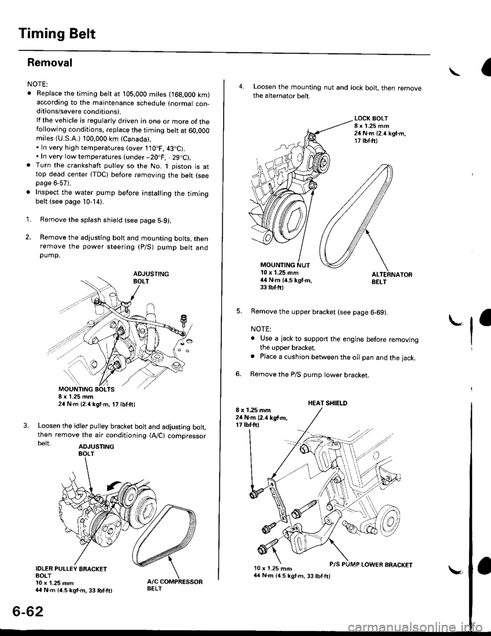
Removal
NOTE:
. Replace the timing belt at 105,000 mites (168,000 km)according to the maintenance schedule (normal con-ditions/severe conditions).
lf the vehicle is regularly driven in one or more of thefollowing conditions, replace the timing belt at 60,OOOmiles (U.S.A.) 100,000 km {Canada).. In very high temperatures (over 110"F, 43"C).. In very low temperatures (under -20.F, 29.C).. Turn the crankshaft pulley so the No. 1 piston is attop dead center (TDC) before removing the belt (seepage 6-57).
. Inspect the water pump before installing the timingbelt {see page 10-14).
1.
IOLER PULLEY BRACKETEOLT10 x 1.25 mm44 N.m 14.5 kgf.m, 33 bnft)
6-62
Remove the splash shield (see page 5-9).
Remove the adjusting bolt and mounting bolts, thenremove the power steering (P/S) pump belt andpump.
8xL25mm24 N m {2.{ kgf.m, 17 lbf.ft)
Loosen the idler pulley bracket bolt and adjusting bolt,then remove the air conditioning (A,/C) compressorbelt aDJUsnNG
44 N.m 14.5 kgt.m, 33 lbf.ft)
P/S PUMP LOWER ARACKET
a\
4. Loosen the mounting nut and lock bolt, then removethe alternator belt.
LOCK BOLT8 x 1.25 mm24 N.m {2.4 kgt.m.17 rb{.ftl
5. Remove the upper bracket (see page 6-69).
NOTE:
. Use a jack to support the engine before removingthe upper bracket.
o Place a cushion between the oil pan and the jack.
Remove the P/S pump lower bracket
8 x 1.25 mm24 N.m 12.,1 kgf.m,17 tbf.ftl
l0 x 1.25 mm
'-f'
MOUNTING10 x 1.25 mm44 N.m (4.5 kgf.m.33 rbf.fttBELT
HEAT SHIELD
Page 233 of 2189
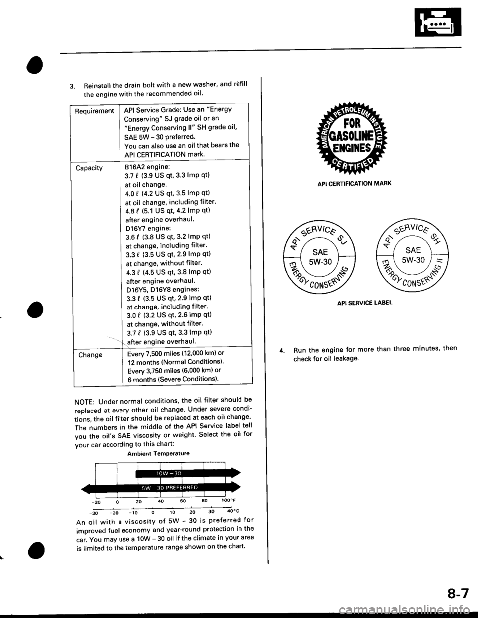
RequirementAPI Service Grade: Use an "Energy
Conserving" SJ grade oil or an"Energy Conserving ll" SH grade oil,
SAE 5W - 30 preferred
You can also use an oil that bears the
API CERTIFICATION mark.
Capacity[atolz engine:
3.7 f (3.9 US qt,3.3 lmp qtl
I at oil change.
J 4.0 r 9.2 US qt, 3.5 lmp qtl
I at oil change, including filter'
| 4.8 f (5.1 Us qt,4.2 lmp qt)
I after engine overhaul
I Dl6Y7 engine:
3.6 f (3.8 US qt, 3.2 lmP qt)
I at change. including filter.
I 3.3 f (3.5 US qt,2.9 lmP qtl
I at change, without filter.
I 4.3 f (4.5 us qt,3.8 lmp qtl
I after engine overhaul.
J D16Y5, D16Y8 engines:
L 3.3 { {3.5 US qt,2.9 lmp qt}
I at change, including filter.
3.01 (3.2 US qt,2.6lmp qt)
I at change, withoutfilter.
3.7 { (3.9 US qt,3.3 lmp qt}- '1.€fter engine overhaul.
ChangeEvery 7,500 miles (12,000 km) or
12 months (Normal Conditions).
Every 3,750 miles (6,000 kml or
6 months (Severe Conditions).
3. Reinstall the drain bolt with a new washer. and rbfill
the engine with the recommended oil.
NOTE: Under normal conditions, the oil filter should be
replaced at every other oil change Under severe condi-
tions, the oilfilter should be replaced at each oil change'
The numbers in the middle of the API Service label tell
you the oil's SAE viscosity or weight Select the oil for
vour car according to this chart:
30 20 -10 010 20 30 4OoC
An oil with a viscosity of 5W - 30 is preferred for
improved tuel economy and year-round protection in the
car. You may use a 10W - 30 oil if the climate in your area
is limited to the temperature range shown on the chart'
Ambient Temoerature
API CERTIFICATION MARK
API SERVICE LABEL
Run the engine tor more than three minutes, then
check for oii leakage
8-7
Page 374 of 2189
3.
5.
6.
1.
Fuel Cut-off Control
. During deceleration with the throttle valve closed, current to the fuel injectors is cut off to improve fuel economy at
speeds over the following rpm:. D16Y5 engine (M/T):850 rpm. D]6Y5 engine (CVT), D'16Y8 engine (USA M/T): 920 rpm
. Dl6Y8 engine (USA A,/I), D16Y7 engine (USA A,/T);910 rpm
. D16Y8 engine (Canada M/T), D16Y7 engine (canada): 990 rpm
' D16Y8 engine (Canada M/T): 1,000 rpm
. 816A2 engine: 970 rpm
. Fuel cut-off action also takes place when engine speed exceeds 6,900 rpm (D16Y5, D16Y7 engine; D'16Y8 engine:
7,000 rpm. 816A2 engine: 8.100 rpm), regardless of the position of the throttle valve, to protect the engine from
over-rewing. With '99 Dl6Y7 engine (A,/T) and '99 D16Y8 engine (A./T), the PCM cuts the fuel at engine speeds over
5,000 rpm when the vehicle is not moving.
IVC Compressor Clutch Relay
When the ECM/PCM receives a demand for cooling from the air conditioning system, it delays the compressor from
being energized, and enriches the mixture to assure smooth transition to the A,/C mode
Evaporative Emission (EVAP) Purge Control Solenoid Valve*'
When the engine coolant temperature is above 154'F (68'C). the ECM/PCM controls the EVAP purge control solenoid
valve which controls vacuum to the EVAP purge control canister.
Evaporative Emission (EVAP) Purge Control Solenoid Valve*a
When the engine coolant temperature above 154"F (68"C), intake air temperature above 32"F (0'C) and vehicle speed
above 0 mile (0 km/h) or [Ay'C compressor clutch on and intake air temperature above 160"F (41'C)], the ECM/PCM
controls the EVAP purge control solenoid valve which controls vacuum to the EVAP purge control canister.
Exhaust Gas Recirculation (EGR) Control Solenoid Valve*?
When EGR is required for control of oxides of nitrogen (NOx) emissions. the ECM controls the EGR control solenoid
valve which supplies regulated vacuum to the EGR valve
Alternator Control
The system controls the voltage generated at the alternator in accordance with the electrical load and driving mode,
which reduces the engine load to improve the fuel economy.
ECM/PCM Fail-safe/Back-up Functions
1. Fail safe Function
When an abnormality occurs in a signal from a sensor, the ECM/PCM ignores that signal and assumes a pre-pro-
grammed value for that sensor that allows the engine to continue to run.
2. Back-uD Function
When an abnormality occurs in the ECM/PCM itself, the fuel injectors are controlled by a back-up circuit independent
of the system in order to permit minimal driving.
3. Self diagnosis Function lMalfunction Indicator Lamp (MlL)l
When an abnormality occurs in a signal from a sensor, the ECM/PCM supplies ground for the lvllL and stores the DTC
in erasable memory. When the ignition is initially turned on, the ECM/PCM supplies ground for the MIL for two sec-
onds to check the MIL bulb condition.
4. Two Trip Detection Method
To prevent false indications, the Two Trip Detection Method is used for the HO2S, fuel metering-related. idle control
system, ECT sensor, EGR system and EVAP control system self-diagnostic functions. When an abnormality occurs,
the ECM/PCM stores it in its memory. When the same abnormality recurs after the ignition switch is turned OFF and
ON 0l) again, the ECM/PCM informs the driver by lighting the MlL. However, to ease troubleshooting, this function is
cancelled when you jump the service check connector. The MIL will then blink immediately when an abnormality
occurs,
5. Two (or Three) Driving Cycle Detection Method
A "Driving Cycle" consists ot starting the engine. beginning closed loop operation, and stopping the engine. lf misfir-
ing that increases emissions is detected during two consecutive driving cycles, or TWC deterioration is detected dur-
ing three consecutive driving cycles, the ECM/PCM turns the MIL on. However, to ease troubleshooting, this function
is cancelled when you jump the service check connector. The MIL will then blink immediately when an abnormality
occurs.
(cont'd)
1 1-1 05
.1.
Page 415 of 2189
PGM-FI System
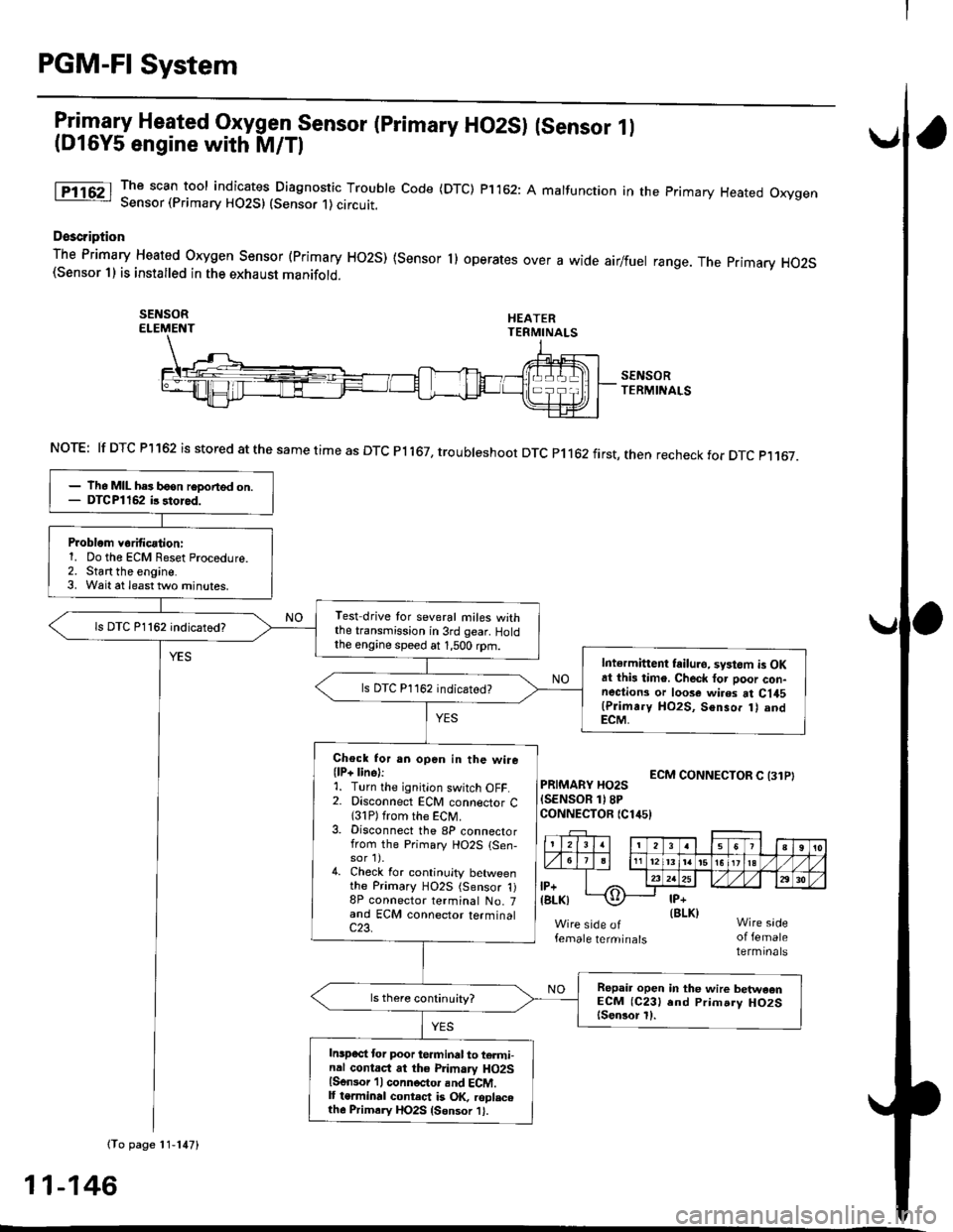
Itil-"w Heated Oxygen Sensor (primary HO2S) (sensor 1l(Dl6Y5 engine with M/Tl
The scan tool indicates Diagnostic Trouble Code (DTC) p1162: A malfunction in the primary Heated OxygenSensor (Primary HO2S) (Sensor 1) circutt.
Doscription
The Primary Heated orygen sensor (Primary Ho2s) {sensor 1) operates over a wide airlfuel range. The primary Ho2S(Sensor 1) is installed in the exhaust manifold.
SEI{SORELEMENT
SENSORTERMINALS
ECM CONNECTOR C (31PIPRIMARY HO2S(SENSOR 1)8PCONNECTOR {Clir5)
female terminalsof femaleterminals
NOTE: lf DTC Pl162 is stored at the same time as DTC Pl167, troubteshoot DTC p1162 first, then recheck for DTC p1167.
(To page 11-147)
- lh6 MIL hes b6on reDorted on.- DTCPl162 ir 3tored.
Problom v6rificationi1. Do the ECM Reset Procedure.2. Start the engine.3. Wait at least tlvo minutes.
Test drive tor several miles withthe transmission in 3rd gear. Holdthe engine speed at 1,500 rpm.
ls DTC P1162 indicatod?
Intermittent tailuro, systom is OKat this timo. Check tor poor con-nections or loose wires at C145(Plimr.y HO2S, Senso. t) andECM,
ls DTC P1162 indicated?
Chock for an open in the wire(lP+ lins):1. Turn the ignition switch OFF.2. Disconnect ECM connector C{31P) from the ECM.3. Disconnect the 8P connectorfrom the Primary HO2S {Sen-sor 1).4. Check for continuity betweenthe Primary HO2S (Sensor 1)8P connector terminal No. 7and ECM connector terminalc23.
Repair open in the wire betwaonECM (C231 end Prim.ry HO2Slsen3or l).
Inspect lor poor terminal to termi-nal contact at the Primary HO2Slsensor 'l I connoctor and ECM.It terminal contect is OK, roplacelh6 Primrry HO2S {Sensor 1}.
11-146
Page 458 of 2189
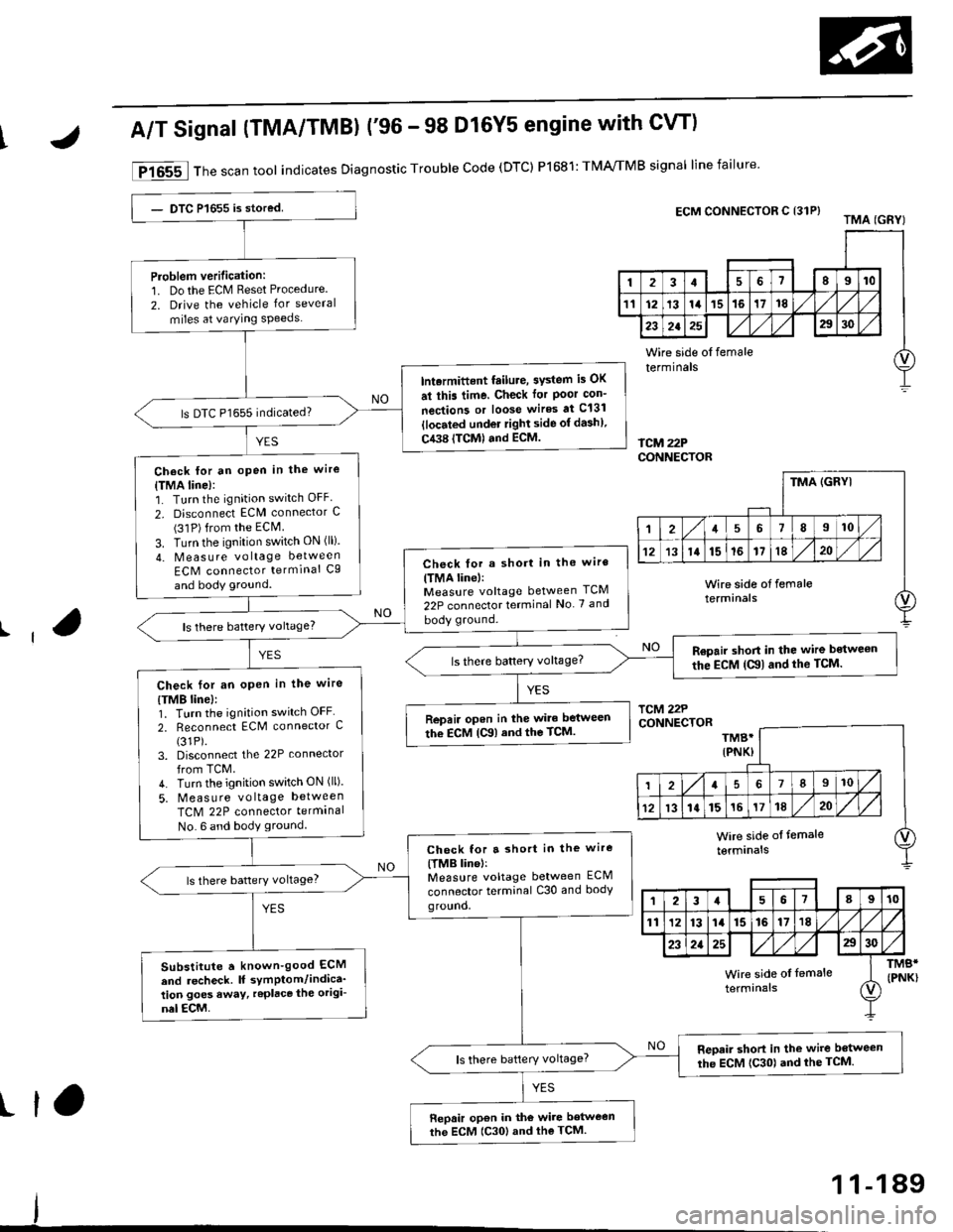
[F16551l Th" ""un toot indicates Diagnostic Trouble Code (DTC) P1681: TIVA,/TMB signal line failure
Problem verification:1. Do the ECM Reset Procedure.
2. Drive the vehicle Ior several
miles at varying speeds
lnt.rmittent failure, system is OK
at ihis time. Check tor Poor con-
nections or loos€ wires at C131
llocated under right side of dash),
C438 ITCM) and ECM.
ls DTC P1655 indicated?
Check lor an oPen in the wire(TMA line):1. Turn the ignition switch OFF
2. Disconnect ECM connector C(31P)from the ECM
3. Turn the ignition switch ON (ll).
4- Measure vo ltag e between
ECM connector terminal Cg
and body ground.
Check for a short in the wire
ITMA line,:Measure voltage between TCM
22P connector terminal No 7 and
body ground.ls there battery vohage?
Ropair shod in the wire bstwe€n
the EcM (C!l) and the TcM.ls there battery voltage?
Check for an open in the wire
{TMB line}:1. Turn the ignition switch OFF
2. Reconnect ECM connector c(31P).
3. Disconnect the 22P connector
from TCM.4. Turn the ignition switch ON (ll).
5. Measure vo ltage between
TCM 22P connector termlnal
No. 6 and body ground.
Repair open in the wire between
th€ EcM {Ca) and the TcM.
Check for a 3ho.t in the wire
{TMB lin6,:Measure voltage between ECM
connector terminal C30 and bodyground,
ls there battery voltage?
Substitute a known'good ECM
and recheck. It symPtom/indica'tion goes away, teplace the origi-
nal ECM.
Reoair short in the wile b6tween
the ECM {C30} and the TCM.ls there baftery voltage?
f,epair open in the wire between
the EcM (C30) and the TcM.
IJA/T Signal (TMA/TMBI ('96 - 98 Dl6Y5 engine with GW)
ECM CONNECTOR C 131P}TMA IGRYI
fcu22PCONNECTOR
ll
TMB*{PNK}
231678910
1t'12131415161718
232a252930
Wire side oI temale
terminals
tl,
1 1-189
Page 513 of 2189
lntake Air System
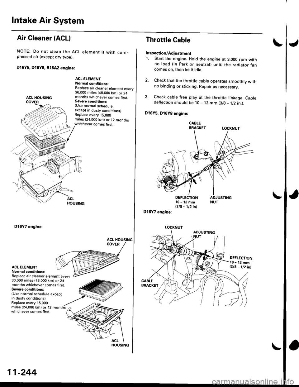
Air Cleaner (ACLI
NOTE: Do not clean the ACL element it with com-pressed air {except dry type).
D16Y5, D16Y8, 816A2 engine:
ACL ELEMENTNormal conditions:Replace air cleaner element every30,000 miles (48,000 km) or 24months whichever comes first.S€voae conditions:(Use normal scheduleexcept in dusty conditions)Replace every 15,OOOmiles (24,000 km)or 12 monthswhichever comes first.
D16Y7 engine:
ACL ELEMENTNormal conditions:Replace air cleaner element every30,000 miles (48,000 km) or 24months whichever comes first,Seve.s conditions:(Use normal schedule exceptin dusty conditions)Replace every l5,000
whichever comes first.
11-244
Throttle Cable
Inspection/Adiustment
1. Start the engine. Hold the engine at 3,000 rpm withno load (in Park or neutral) until the radiator fancomes on, then let it idle.
2. Check that the throftle cable operates smoothly withno binding or sticking. Repair as necessary.
3. Check cable free play at the throttle linkage. Cabledeflection shoutd be 10- l2 mm (3/B - 112 in.l.
D16Y5, D16Y8 engine:
CABLEBRACKETLOCKNUT
DEFLECTION10-12mm
BIA- 112 inl
D16Y7 engine:
LOCKNUT
DEFLECTION10- 12 mml3lA - lninl
Page 536 of 2189

1\
Evaporative Emission (EVAPI Controls
Description
The evaporative emission controls are designed to minimize the amount of fuel vapor escaping to the atmosphere. The
system consists of the foliowing components:
A. Evaporative Emission (EVAP) Control Canisto]
An EVAP control canister is used for the temporary storage of fuel vapor until the fuel vapor can be purged from the
EVAP control canister into the engine and burned.
B. Vapor Purge Control System
EVAP control canister purging is accomplished by drawing fresh air through the EVAP control canister and into a port
on the intake manifold. The purging vacuum is controlled by the EVAP purge control solenoid valve.
I'96 D16Y5 engine,'96 Dl6Y7 engine,'96 D16Y8
engine (sedan),'97 D16Y5 engine,'97 D16Y7
engine (couper KA, KC models, sedan: KA, Kc'
KL iDX) models, hatchback: all models), '97
D 16Y8 engine (sedan: KA, KC models)l
I'96 D16Y8 engine (coupe),'97 D16Y7 engine
(coupe: KL model, sedan: KL (LX) model)"97
D16Y8 engine (coupe: all models, sedan: KL model)'98-all models,'99-all models,'00-all modelsl
I
c.
D.
or
l'lc COMPRESSOR CLUTCH ON
and
INTAKE AIR TEMPERATURE ABOVE 160"F (41'C)
Fuel Tank Vapor Control System
When fuel vapor pressure in the fuel tank is higher than the set value of the EVAP two way valve, the valve opens and
regulates the flow of fuel vapor to the EVAP control canister.
Onboard Refueling Vapor Recovery (ORVRI System {'99 - 00 models}
During refueling. the oRVR {onboard Refueling Vapor Recovery) vent shut valve opens with the pressure in the fuel
tank. and feeds the fuel vapor to the EVAP control canister.
t(cont'd)
11-267
EVAP PURGE CONTROL SOLENOID VALVE DUTY CON-
TROLLED AFTER STARTING ENGINE
ENGINE COOLANT TEMPERATURE ABOVE 154'F {68"C)
INTAKE AIR TEMPERATURE ABOVE 32'F (O'C)
and
VEHICLE SPEED ABOVE O MILE (O KM/h}
ENGINE COOLANT TEMPERATURE ABOVE 154'F (68'C)
Page 976 of 2189
Fluid Level
l.Checking/Changing
CAUTION: while chscking and changing, be sure not to
allow dust and other toreign particles to ent€l inlo the
transmission.
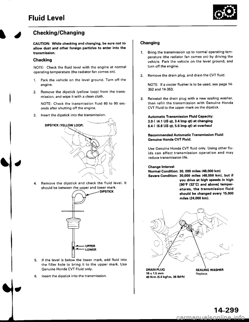
Checking
NOTE: Check the fluid level with the engine at normal
operating temperature (the radiator fan comes on).
'1. Park the vehicle on the level ground. Turn oft the
engrne.
2. Remove the dipstick (yellow loop) from the trans-
mission, and wipe lt with a clean cloth.
NOTE: Check the transmission fluid 50 to 90 sec-
onds after shutting off the engine.
3. Insert the diDstick into the transmission.
DIPSTICK (YELLOW LOOPI
Remove the dipstick and check the fluid level.
should be between the uDDer and lower mark.DIPSTICK
5. lf the level is below the lower mark, add fluid into
the filler hole to bring it to the upper mark. Use
Genuine Honda CW Fluid only.
6. Insert the dipstick into the transmission.
14-299
Changing
1. Bring the transmission up to normal operating tem-
perature (the radiator fan comes on) by driving the
vehicle. Park the vehicle on the level ground, and
turn off the engine.
2. Bemove the drain plug, and drain the CVT fluid.
NOTE| lf a cooler flusher is to be used, see page 14-
352 and 14-353.
Reinstall the drain plug with a new sealing washer,
then refill the transmission with Genuine Honda
CVT Fluid to the upper mark on the dipstick.
Automatic Transmission Fluid CaPacity:
3.9 i (4.r US qt. 3.4 lmp qt) 8t chlnging
6.4 I (6.8 US qt, 5.6 lmp qt) 8t ov€lhaul
Rscommended Automatic Transmission Fluid:
Genuine Honda CVT Fluid-
Use Genuine Honda CW fluid only. Using other flu-
ids can affect transmission operation and may
reduce transmission liJe.
Change Interval:
Normal Condition: 30, 000 miles 148,000 km)
Severe Condition: 30,000 miles (48,000 km), but it
you drive at high sPeeds in high
t90"F (32'C) and abovol temper-
atures, the ttansmission fluid
should be changed evsrY 15,000
miles 124,000 km).
{-]lr
ORAIN PLUG18 x 1.5 mma9 N.7n (5.0 kgl.m, 36 lb{'ftl
SEALING WASHERReplace.