Suspension arms HONDA CIVIC 1999 6.G Workshop Manual
[x] Cancel search | Manufacturer: HONDA, Model Year: 1999, Model line: CIVIC, Model: HONDA CIVIC 1999 6.GPages: 2189, PDF Size: 69.39 MB
Page 45 of 2189
Towing
lf the vehicle needs to be towed, call a professional tow-
ing service. Never tow the vehicle behind another vehi
cle with iust a rope or chain lt is very dangerous'
Emergency Towing
There are three popular methods of towing a vehicle:
Flat-bed Equipment - The operator loads the vehicle on
the back of a truck. This is the best way of transporting the
vehicle.
Wheel Lift Equipment - The tow truck uses t\ivo pivoting
arms that go under the tires {front or rear} and lifts them
off the ground. The other two wheels remain on the
ground.
Sling-type Equipment - The tow truck uses metal cables
with hooks on the ends. These hooks go around parts of
the frame or suspension, and the cables lift that end of
the vehicle off the ground The vehicle's suspension and
body can be seriously damaged if this method of towing
is attemDted.
lf the vehicle cannot be transported by flat-bed. it should
be towed with the front wheels off the ground lf due to
damage, the vehicle must be towed with the front
wheels on the ground, do the following:
lvlanual Transmission and CW
. Release the parking brake
. Shift the transmission to neutral (CW to E position)'
Automatic Transmission
. Release the Parking brake.
. Sta rt the engine.
. Shift to LDll position, then E position.
. Turn oif the engine
CAUTION;
o lmploper towing preparation will damage ihe tfans-
mission. Follow the above procedute exaqtly lf you
cannot shift the tlansmission or start the engino
laulomatic transmissionl, yout vehicle must be trans-
ported on a flat-bed.
. lt is best to tow the vehicle no farther than 50 mil€s
(80 km), and ksop thE speed below 35 mph (55 km/hl
. Trying to lift 01 tow your vehicle by tho bump€F will
caus€ setious damagg. Ths bumpers are not dEigned
to supportthe vshicle's weigh.
tJO
1-43
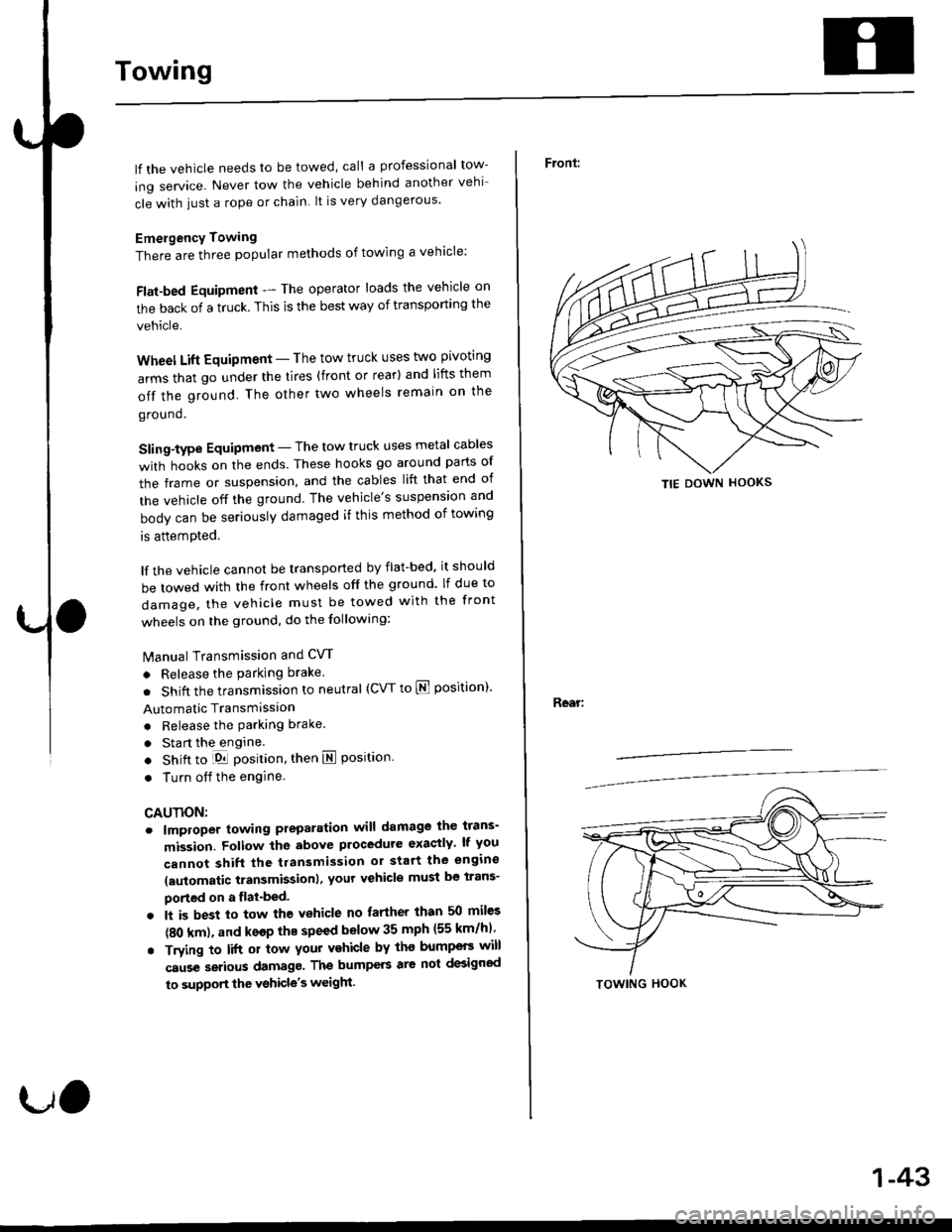
Front:
Rear:
TIE DOWN HOOKS
TOWING HOOK
Page 1125 of 2189
)
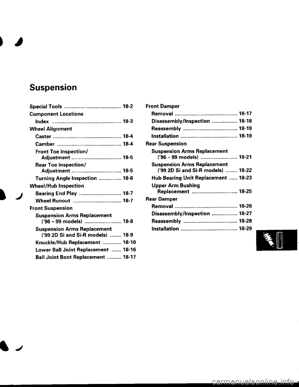
Suspension
Special Tools ............. 18-2
Component Locations
lndex ,,.............. ...... f8-3
Wheel Alignment
Caster .............. ....... 18-4
Camber .................. l8-4
Front Toe Inspection/
Adiustment ........ 18-5
Rear Toe lnspection/
Adiustment ........ 18-5
Turning Angle Inspection ................ 18-6
Wheel/Hub Inspection
Bearing End P|ay .............................. l8-7
Wheel Runout ....... 18-7
Front Suspension
Suspension Arms Replacement
('96 - 99 modelsl .......................... 18-8
Suspension Arms Replacement
('99 2D Si and Si-R models) ........ 18-9
Knuckle/Hub Replacement ............. 18-10
Lower Ball Joint Replacement ....... 18-16
Ball Joint Boot Replacement .......... 18-17
Front Damper
Removal ................. 18-17
Disassembly/1nspection .................. 18-18
Reassembly ........... 18-19
lnstallation ............. 18-19
Rear Suspension
Suspension Arms Replacement
('96 - 99 models) ....................,..... 18-21
Suspension Arms Replacement
('99 2D Si and Si-R models) ........ 1A-22
Hub Bearing Unit Replacement ...... 18-23
Upper Arm Eushing
Replacement .....18-25
Rear Damper
Removal ................. 18-26
Disassembly/|nspection ............. ..... 1A-27
Reassembly ........... 18-28
lnstallation ............. 18-29
lr
Page 1132 of 2189
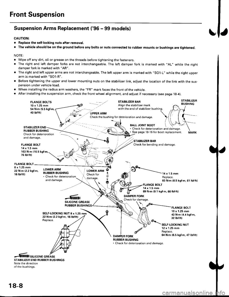
Front Suspension
Suspension Arms Replacement ('96 - 99 models)
CAUTION:
. Replace the selt-locking nuts after removal.
. The vehicle should be on the ground betore any bolts or nuts connected to rubber mounts or bushings are tightened.
NOTE:
. Wipe off any dirt, oil or grease on the threads before tightening the fasteners.. The right and left damper forks are not interchangeable. The left damper fork is marked with "AL" while the rightdamper fork is marked with "AR'
. The right and left upper arms are not interchangeable. The left upper arm is marked with "SO1-L" while the right upperarm is marked with "SOl-R".
. Before tightening the upper and lower mounting nuts on the stabilizer link, adjust the location of the link with the sus-pension under vehicle load.
. When installing the radius arm washers, the "FR" mark faces the front ofthe vehicle.. After installing the suspension arm, ch eck the front wheel alignment, and adjust if necessary (see page 18-4).
FLANGE BOLTS10 x 1.25 mm54 N.m 15.5 kgl.m,40 tbf.ftl
STAEILIZER ENDRUBBER BUSHING
BALL JOINT BOOT. Check for deterioration and damage.. See page 18-16 for boot replacement.
STABILIZER BARCheck for bending and damage.
Check for deterioration - ---\--
and damage, -\
FLANGE BOLT14 x 1.5 mm/)l103 N.m {10.5 kg{.m,. t, ,/4,76lb{.ft) t,,"-iV
v:\FLANGE BOLT-
;iffillr-"- ilHitffi*::,"*"
and damaoe,
o.'-----------14 x 1.5 mmReplace.83 N.m {8.5 kgf.m, 61 lbf.ftl
LOWER ARMCheck for
c
JlTTda
1{ x 1.5 mm89 N.m {9.1 kgt m. 66 lbtft)
-6;SILICONE GREASERUBBER BUSHING
DAMPER FORKCheck for damage.
SELF-LOCKING NUT I x 1.2522 N.m (2.2 kg{.m, 16lbf.ftlReplace.
FLANGE BOLT10 x 1.25 mm€ N.m {4.6 kgt m.32 tbf.ft)
SELF-LOCKING NUT12x 1.25 mmReplace.6it N m {6.5 kgf.m, 47 lbf.ftl
RUEBER BUSHING. Check for deterioration and damage.
.6t",.,"o".c"KeSTAAIL|zER END RUBBER EUSHINGSNote the directionof the bushings.
18-8
Page 1133 of 2189
I
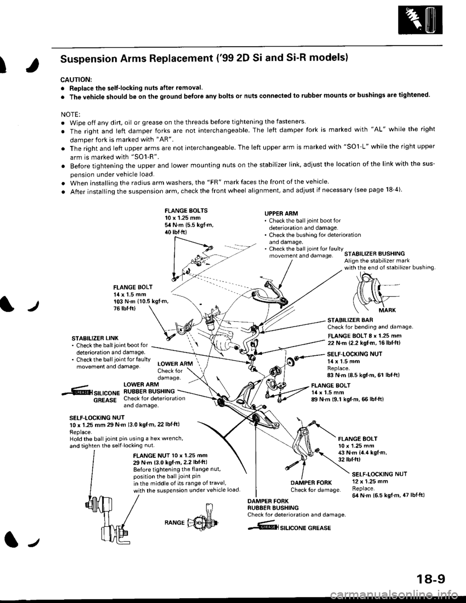
Suspension Arms Replacement ('99 2D Si and Si-R models)
CAUTION:
. Replace the selt-locking nuts after removal.
. The vehicle should be on the ground belore any bolts or nuts connected to rubber mounts or bushings are tightened.
NOTE:
. Wipe off any dirt, oil or grease on the threads before tightening the fasteners
. The right and ieft damper forks are not interchangeable. The left damper fork is marked with "AL" while the right
damper fork is marked with "AR"
. The right and left upper arms are not interchangeable. The left upper arm is marked with "SOl-L" while the right upper
arm is marked with "SO1-R".
. Before tightening the upper and lower mounting nuts on the stabilizer link, adiust the location of the link with the sus-
pension under vehicle load.
. When installing the radius arm washers, the "FR" mark faces the front of the vehicle.
. After installing the suspension arm, check the front wheel alignment, and adjust if necessary (see page 18-4).
FLANGE BOLTS10 x 1.25 mmsit N.m 15.5 kgf.m,40 tbtftl
UPPER ARM' Check the ball joint boot fordeterioration and damage.. Check the bushing for deteriorationano oamage,. Check the ball ioint fo. faultymovement and clamage.STABILIZER BUSHINGAlign the stabilizer markwith the end of stabilizer bushing
FLANGE BOLT14 x 1.5 mm
l./
103 N.m (10.5 kgf.m,76 tbr.ftl
STABILIZER LINK. Check the ballioint bootfordeterioration and damage.. Checkthe ballioint tor faultymovement and damage.
STABILIZER BARCheck for bending and damage.
FLANGE BOLT 8 x 1.25 mm22 N.m (2.2 kgf.m, 16lbf.ft)
SELF-LOCKING NUT14 x 1.5 mmReplace.83 N.m 18.5 kgf m, 61 lbf.ft)
-.6r srr-,co", hSHrtlrT.[*"u
6g619g Check for deteriorationano oamage.
SELF.LOCKING NUT10 x 1.25 mm 29 N m 13.0 kgf m, 22 lbf ftl
Replace.Hold the ball ioint pin using a hex wrench,
and taghten the self'locking nut.
LOWER ARMCheck fordamage.
FLANGE NUT l0 x 1.25 mm
29 N.m 13.0 kgI m,2.2 lbf ft)
Before tightening the {lange nut,position the ball joint Pinin the middle of its range of travel,
with the suspension under vehicle load
FLANGE BOLT14 x 1.5 mm89 N.m 19.1 kgf.m, 66 lbf.ft)
FLANGE BOLT10 x '1.25 mm43 N.m {4.4 kgf.m,32 tbtft)
DAMP€R FORKCheck lor damage.
DAMPER FORKRU88ER BUSHINGCheck for deterioration and damage.
4@lsrlrcoNE GREASE
SELF.LOCKING NUT12 x 1.25 mmReplace.64 N m 16.5 kgl.m, 47 lblft)
J
RANGE
18-9
Page 1145 of 2189
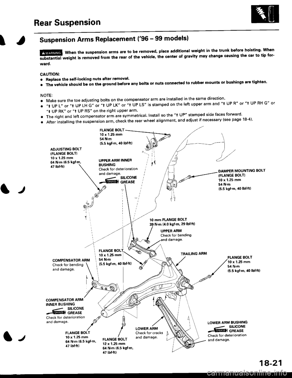
Rear Suspension
ISuspension Arms Replacement ('96 - 99 modelsl
tffi Whsn ths suspension arms ar6 to be removed. place additionsl weight in the trunk bafore hoisting' Wh€n
-substantial weight is removed ftom th6 teal of ths vehicl6, the center of gravity may change causing ths cat to tip tor'
ward.
CAUTION:
. Replace the selt-locking nuts after removal.
.Thgvehic|eshouldb€onthggroundboforeanybohsornutsconnectodtorubbelmountso]bughingsaretighton.
NOTE:
. Make sure the toe adjusting bolts on the compensator arm are installed in the same direction'
. ,,t UP 1,, or ,,t UP LH G,. or ,.t UP LK,, or "t UP LS'. is stamped on the |eft upper arm and ,,t UP R" or "t UP RH G., or
"t UP RK" or "t UP RS" on the right upper arm'
. The rightand left "ornp"n""to, uitt rre symmetrical lnstall sothe "t UP" stamped side faces forward'
.Afterinsta||ingthesuspens|onarm,checktherearwhee|alignment,andadjustifnecessary(seepagelS-4).
FLANGE BOLT10 x 1.25 mm54 N.m
ADJUSTING BOLT(FLANGE BOLTI10 x 1.25 mm
BUSHINGCheck for deteriorationand oamage.
(5.5 kgf'm, 40 lbf'ftl
UPPER ARM INNER
47 tbf.ftl
tJ
l0 mm FLANGE BOLT
N.m t4.0 kst m, 29lblftl
DAMPER MOUNTING BOLT(FLANGE BOLT}
10 x 1.25 mm
54Nm(5.5 kgd.m, iro lbf'ft)
FI.ANGE BOLT10 x 1,25 mm54 N.m(5,5 ksrf.m, 4{} lbf'ft}
UPPER ARMCheck for bendangdamage-
TRAILING ARM
COMPENSATOR ARM
Check for bendingano oamage,
COMPENSATOR ARM
INNER BUSHING
.- SILICONE.@] GREASE
Check tor deteriorataonand damage.
FLANGE BOLT10 x 1.25 mm64 N.m {6.5 kgt'm,47 lbf.ft)
LOWER ARMCheck for cracksano damage.
LOWEN ARM BUSHING
.,- SILICONE..i@l GREASECheck for deteriorationand oamage,FLANGE AOLT12 x 1.25 mm64 N.m {6.5 kgf m,47 tbf.ftt
FLANGE BOL10 x 1.25 mm
I 54 N.m
(5.5 ksrm, ao lbf'ftl
1A-21
Page 1146 of 2189
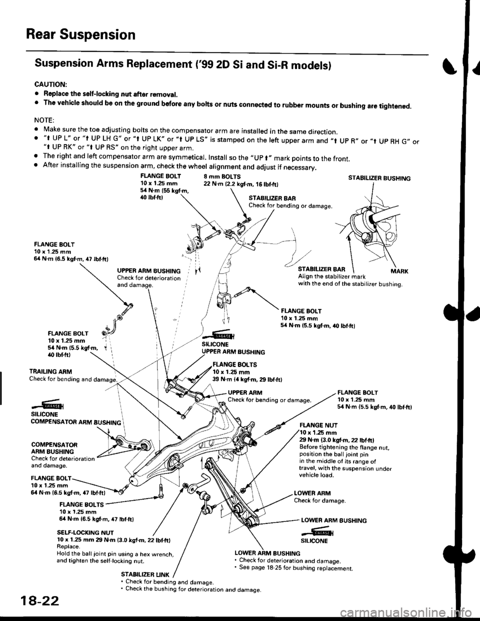
Rear Suspension
Suspension Arms Replacement ('gg 2D Si and Si-R models)
CAUTION:
. Roplace the self-locking nut after removal.' The vehicle should be on the gtound before any bohs or nuls connected to rubber mounts or bushing are tightened.
NOTE:
' Make sure the toe adjusting borts on the compensator arm are insta|ed in the same direction.. "t UP L" or "t UP LH G" or "t Up LK" or "l Up LS,, is stamped on the left upper arm and ,,t Up R,, or "t Up RH G,,"i UP RK" or "t UP RS" on the right upper arm.. The right and left compensator arm are symmeticar. Install sothe"upr"markpointstothefront.. After installing the suspension arm, check the wheel atignment and adiust if necessary,
FLANGE BOLT'10 x 1.25 mm54Nm155kgl.m,,rc lbf.ftl
8 rhm BOLTS22 N.m {2.2 kgf.m, 16 tbtfrlSTABILIZER BUSHTNG
FLANGE BOLT10 x 1.25 rnm54 N.m {5.5 kgt m, iro lbf.ft)
STAEILIZER BARCheck for bending or damage.
FLANGE BOLT10 x 1 .25 mm64 N m {5.5 kgf.m,47 lbtftl
FLANGE BOLT10 x 1.25 mm54 N.m 15.5 *gf.m,
and
UPPER ARM BUSHINGCheck for deteriorationAlign the stabitizer markwith the end ot the stabilizer bushing.
FLANGE BOLT'10 x 1.25 mm54 N.m 15.5 kgt.m, a0 lbtftl
stLrcoNEUPPER ARM BUSHINGiO lbf.ftl
TRAILING ARMCheck for bending and
EOLTS10 x 1.25 mm39 N m ll kgf.m, 29 lbf.ft)
UPPER ARMCheck for b€nding or damage.#@lstLtcoNECOMPENSATOR ARM BUSHING
COMPENSATORARM BUSHINGCheck for deteriorationand damage.
FLANGE NUTr '1.25 mm29 N.m {3.0 ksl.m,22 lbtft}Belore tightening the flange nut,position the ball joint pinin the middle ol its range oftravel, with the suspension undervehicle load.
LOWER ARMCheck for damage-
BUSHING
FLANGE BOLTl0 x 1.25 mm6l N.m 16.5 kg{.m, a7 lbt.ftl
FLANGE BOLTS10 x 1,25 mm64 N.m {6.5 kgf.m, 47 lbf.ftl
SELF.LOCKNG NUT
LOWER ARM
-GrstltcoNE10 x 1.25 mm 29 N.m (3.0 ksl.m, 22 tbtfrlReplace.Hold the ball ioinl pin using a hex w.enct.and tighten the selfjocking nut.
STABILIZEB LINK
LOWER ARM BUSHING. Check for deterioration and damaoe.' See page 18 25 for bushing replaciement.
' Check for bending and damage.. Check the bushing for deterioration ano oamage.
18-22