alternator charging system HONDA CIVIC 1999 6.G Workshop Manual
[x] Cancel search | Manufacturer: HONDA, Model Year: 1999, Model line: CIVIC, Model: HONDA CIVIC 1999 6.GPages: 2189, PDF Size: 69.39 MB
Page 373 of 2189
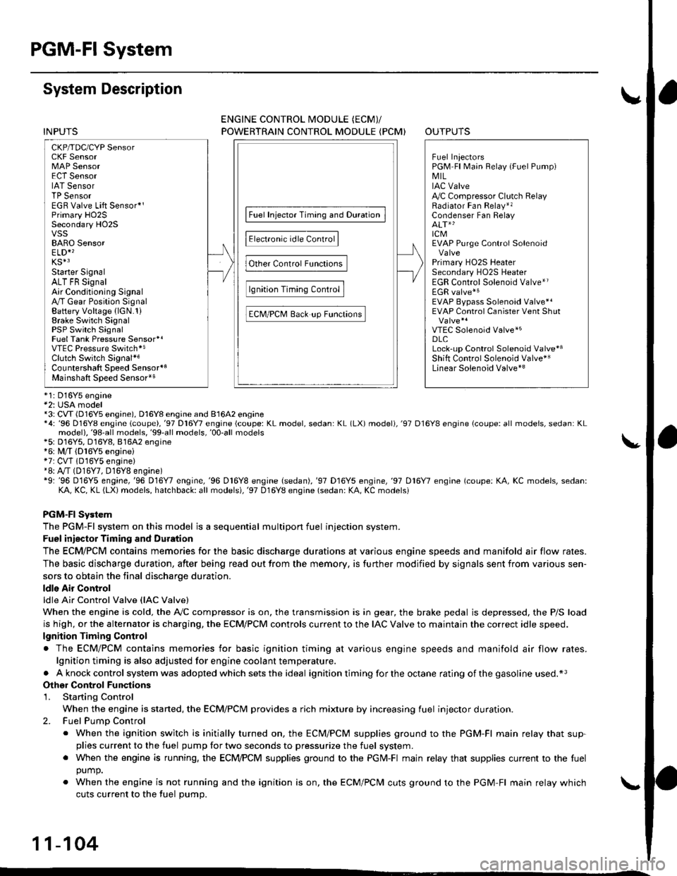
PGM-FI System
System Description
CKP/TDC/CYP Sensor
MAP Sensor
IAT SensorTP SensorEGR Valve Lift Sensor*'Primary H02SSecondary HO2SVSSBARO SensorELD*'KS€Starter SignalALT FR SignalAir Conditioning SignalA/T Gear Position SignalBattery Voltage {lGN.1}Erake Switch SignalPSP Switch SignalFuel Tank Pressure Sensor*iVTEC Pressure Switch*5Clutch Switch Signal*6Countershaft Speed SensornBMainshaft Speed Sensorrs
-\
----t /
F;ilrr j"-----fi-tri-'r.;l
Fb"t."'i" d" c;;il
F,h"'c;;tr*".io";-l
@."r.l"sc;;ll
EaM/PcM B""k-p F"""till
r\
-:/
Fuel IniectorsPGM-Fl Main Belay {Fuel Pump)MILIAC Valve!y'C Compressor Clutch RelayRadiator Fan Relay*,Condenser Fan RelayALT*'lcMEVAP Purge Control Solenoid
Primary HO2S HeaterSecondary H02S HeaterEGR Control Solenoid Valve*rEGR valve*6EVAP Bypass Solenoid Valve*'EVAP Control Canister Vent Shut
VTEC Solenoid Valve*5DLCLock-up Control Solenoid Valve*aShift Control Solenoid Valve*3Linear Solenoid Valve*3
*1: Dl6Y5 engine*2: USA model*3: CW (D16Y5 ensine), D16Y8 engine and 81642 ensine*4: '96 D16Y8 engine lcoupe),'97 Dl6Y7 engine (coupe: KL model, sedan: KL (LX) model),'97 D16Y8 engine {coupe: all models, sedan: KLmodel),'98-all models,'99'all models,'00-all models+5: D16Y5, D16Y8,816A2 engine*6: M/T (D16Y5 enginei*7: CVT 1D'l6Y5 engine)+8: A/T (D16Y7, D16Y8 engine)*9: '96 D16Y5 engine,'96 D16Y7 engine,'96 Dl6Y8 engine (sedan),'97 D16Y5 engine,'97 Dl6Y7 engine (coupe: KA, KC models, sedan:KA, KC, KL (LX) models, hatchback: all models),'97 D16Y8 engine (sedan: KA, KC modelsi
PGM-FI Sy3lem
The PGM-Fl system on this model is a sequential multipon fuel injection system.
Fuel iniector Timing and Duration
The ECM/PCM contains memories for the basic discharge durations at various engine speeds and manifold air flow rates.
The basic discharge duration, after being read out from the memory. is further modified by signals sent from various sen-
sors to obtain the final discharge duration.
ldle Air Control
ldle Air Control Valve llAC Valve)
When the engine is cold. the A,/C compressor is on, the transmission is in gear, the brake pedal is depressed, the P/S load
is high, or the alternator is charging, the ECM/PCM controls current to the IAC Valve to maintain the correct idle speed.
lgnition Timing Control
. The ECM/PCM contains memories for basic ignition timing at various engine speeds and manifold air flow rates.
lgnition timing is also adjusted for engine coolant temperature.
. Aknockcontrol system was adopted which sets the ideal ignition timing for the octane rating ofthegasoline used.*3
Othgr Control Funqtions
1. Starting Control
When the engine is started, the ECM/PCM provides a rich mixture by increasing fuel injector duration.
2. Fuel Pump Control
. When the ignition switch is initially turned on, the ECM/PCM supplies ground to the PGM-Fl main relay that sup-plies current to the fuel pump for two seconds to pressurize the fuel system.. When the engine is running, the ECI\4PCM supplies ground to the PGM-FI majn relay that supplies current to the fuel
oumo.
. When the engine is not running and the ignition is on, the ECM/PCM cuts ground to the PGM-FI main relay which
cuts current to the fuel pump.
11-104
INPUTS
ENGINE CONTROL MODULE (ECMY
POWERTRAIN CONTROL MODULE (PCM) OUTPUTS
Page 477 of 2189
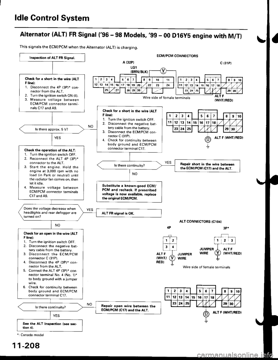
ldle Control System
Alternator (ALTI FR Signal {'96 - 98 Models,'99 - 00 Dl6y5 engine with M/Tl
ECM/PCM CONNECTORS
a {32P)
LGl(BRN/BLK)
Wire side of female terminals
ALT CONNECTORS IC1O4I
JUMPER
JUMPER WIRE
WIRE
Wire side of female terminals
ALT F{WHT/REO)
This signals the ECM/PCM when the Alternator (ALT) is charging.
Inspoction of ALT FR Signal.
Check tor a short in tfte wire (ALTF linel:1. oisconnect the 4P (3P)* con-nector from the ALT.2. Turn the ignition switch ON (ll).3. M easu re voltage betweenECM/PCM connector terminals C17 and A9.Check lor a sho.t in the wire {ALTF line):r. I urn rne tgn|lton swtlch ul-f,2. Disconnect the negative bat-tery cable from the baftery.3. Disconnect the ECM/PCM connector C {31P).4. Check for continuity betweenbody ground and ECM/PCMconnector terminal C17.
ls there approx. 5 V?
Check th€ operation of the ALT:1. Turn the ignition switch OFF.2. Reconnect the ALT 4P (3P)*connector to the ALT.3. Start the engine. Hold theengine at 3,000 rpm with noload (in Park or neutral) untjlthe radiator fan comes on, thenlet it idle.4. [,4easu re voltage betweenECM/PCM connector terminalsC17 and A9.
Repair short in the wire betwe€nthe ECM/PCM {Cl71and th€ ALT.
Substitute a known-good ECM/PCM and recheck. It prescribedvoltage is now available, roplacethe originrl ECM/PCM.
Does the voltage decrease whenheadlights and rear defogger areturned on?ALT FR signal is OK.
Check tor an open in the wire (AlTF linel:1. Turn the ignition switch OFF.2. Disconnect the negative bat-tery cable from the battery.3. Disco n nect the ECM/PCMconnector C (31P).4. Disconnect the 4P (3P)* con,nector from the ALT.5. Connect the ALT 4P 13P)l connector terminal No. 4 (No. 1)'to body ground with a iumper
6. Check lor continuity betweenbody ground and ECM/PCMconnector terminal C17,
Repair op6n wire botween th€ECM/PCM (C171rnd th€ ALT.ls there continuity?
c {31P)
1178I10
1112131415161718
232125a30
oALT F IWHT/REDI
4P3P*
1 2l
Flr
rr-ri-frwHr/ (V)
neor Y
*: Canada model
11-208
3I78910
1l1213l415161718/l
232125E30
oALT F IWHT/REDI
Page 1582 of 2189
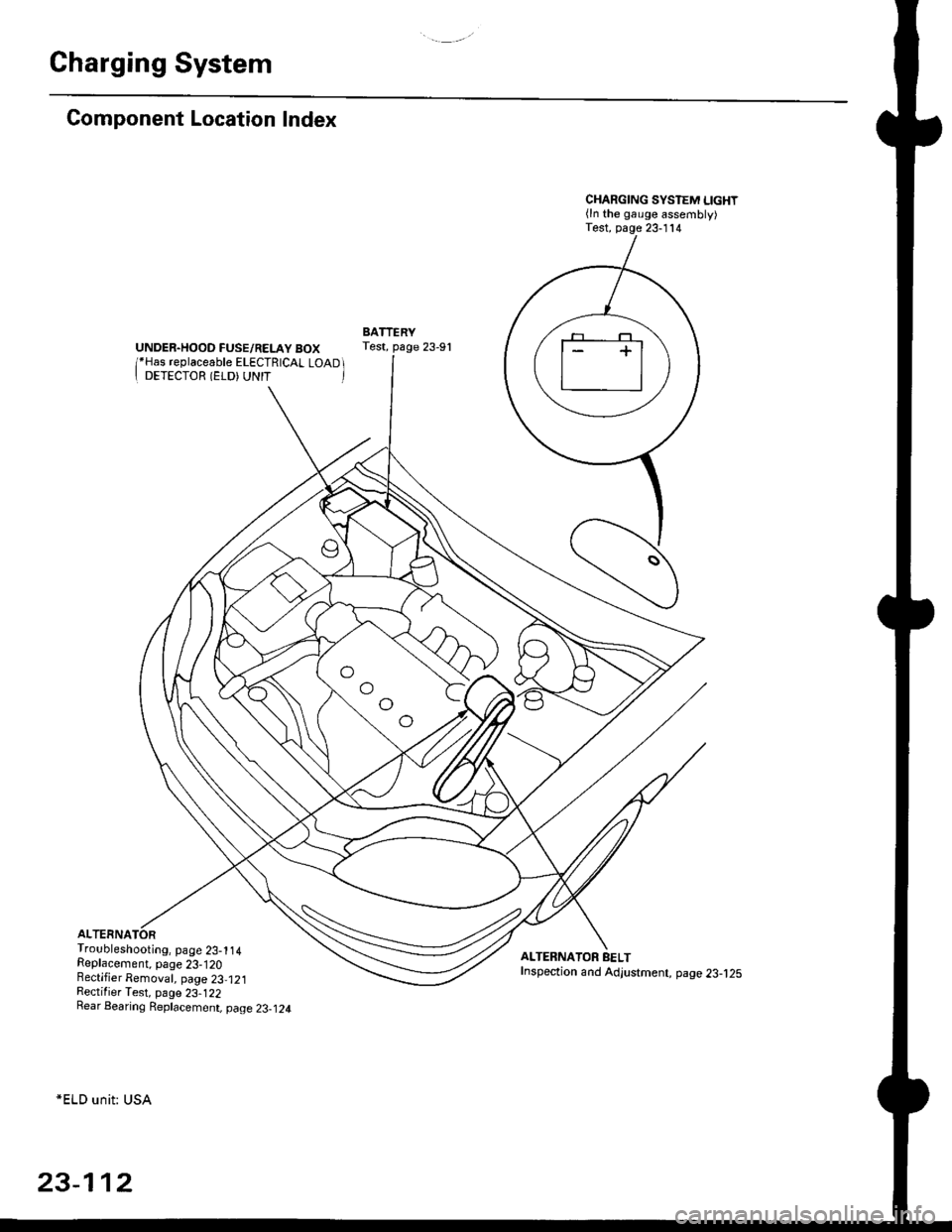
Charging System
Component Location Index
UNDER.HOOD FUSE/RELAY BOX/*Has replaceable ELECTRICAL LOAD II DETECTOR (ELD) UNIT '
Troubleshooting, page 23-1 14Replacement, page 23-120Bectifier Removal, page 23,121Rectifier Test, page 23-122Rear Bearing Replacement, page 23-j24
*ELD unit: USA
CHARGING SYSTEM LIGHT(ln the gauge assembly)Test, page 23- l14
BATTERYTest, page 23-91
ALTERNATOR BELTInspection and Adjustment, page 23-t25
[]
23-112
Page 1584 of 2189
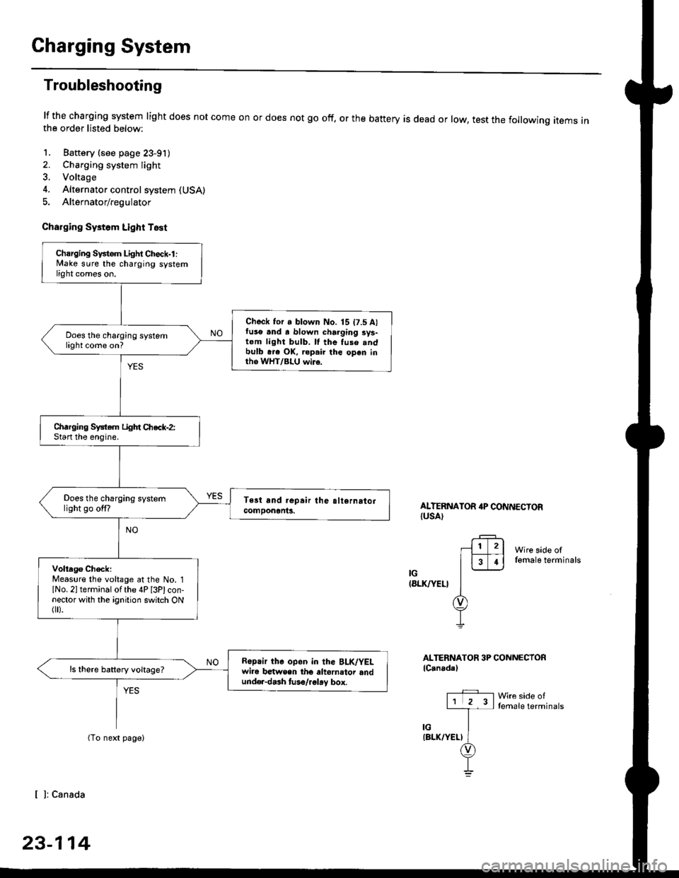
Charging System
Troubleshooting
lf the charging system light does not come onthe order listed below:
1. Baftery (see page 23-91)
2. Charging system light
3. Voltage
4. Alternator control system (USA)
5. Alternator/regulator
Charging Systom Light Test
or does not go off, or the battery is dead or low, test the following items in
ALTERNATOR 4P CONNECTORIUSA)
Wire side offemale terminals
IG(8LK/YEL}
ALTERNATOR 3P CONNECTORlC.nadal
Wre side oftemale terminals
[ ]: Canada
23-114
Charging Svstem Light Check-l :lvlake sure the charging systemlight comes on.
Check for a blown No. 15 t7.5 A)fuso .nd a blown charging sys-tom light bulb. ll the fuse .ndbulb .re OK, ropair the open inth6 WHT/BLU wi16.
Does the charging systemlight come on?
Charging System Light Chec*-2:Start the enoine.
Does the charging systemlight go off?
Volta96 ChecklMeaslre the voltage at the No. 1lNo. 2l terminal of the 4P [3Plcon-nector with the ignition switch ONflr).
R6p.ir the op6n in the BLK/YELwire b€twsen tho altornator andund€r-dash tuso/.glay box.
ls there battery voltage?
Page 1585 of 2189
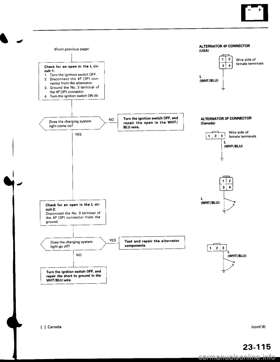
-
Wire side offemale terminals
LtwHT/8LUl
ALTERNATOR 3P CONNECTOR
lCanada)
Wire side oftemale terminals
LIWHT/BLUI
L
{W}IT/BLU)
.+1lr l2l
l3T.l-l-
ir/
(WHT/BLUI
(cont'd)
23-115
{From previous page)
Check tor an open in tho L cir'
cuit-1:1. Turn the ignition switch OFF
2. Disconnect the 4P [3Pl con-
nector from the alternator.
3. Ground the No. 3 terminal of
the 4P l3Plconnector.4. Turn the ignition switch ON (ll)
Turn the ignition swhch OFF, and
rep.ir tho open in tho wHT/
BLU wire.
Does the charging system
light come on?
Check for an open in the L cir-
cuit-2:Disconnect the No 3 terminal o{
the 4P [3PI connector from theground.
Does the charging system
light go off.r
Turn lhe ignition 3whch OFF, and
.epair the 3hort to gtound in the
wHT/Bl-U wire.
ALTERNATOR 4P CONNECTOR(USAI
r?-rl1l2l
FFI
]--
I
I l: canada
Page 1586 of 2189
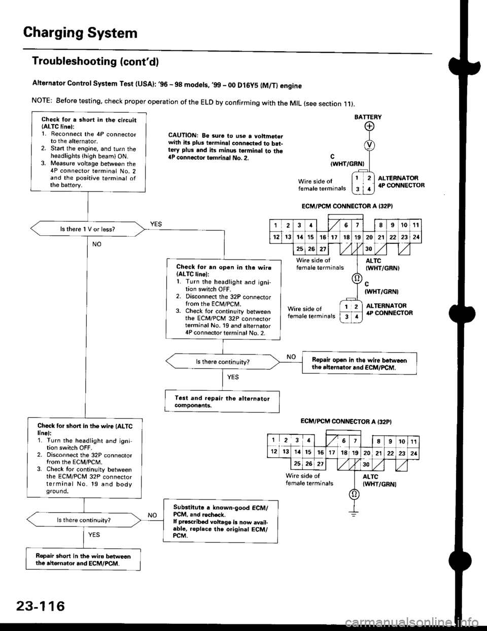
Charging System
Troubleshooting (cont'd)
Alternator Control System Test (USA): ,96 - 98 modets, ,99 _ 00 Dl6y5 (M/Tl engine
NorE: Before testing. check proper operation of the ELD by confirming with the MrL {see section r 1).
BATTERY
CAUTION: Be 3ure to use a voltmot€.with its plus terminal connected to b.t-tery plus and its minus terminal to the{P connectoi tgmrinal No. 2.c
{WHT/GRNt
Wire side oIfemale terminals
ALTERNATOR.P CONNECTOB
Check for a 3hort in the circuitIALTC linel:1. Reconnect the 4P connectorto the alternator,2. Stan the engine, and turn theheadlights {high beam) ON.3. Measure voltage between the4P connector terminal No. 2and the positive terminal ofthe battery.
ls there 1V or less?
Check for rn opon in tha wire(ALTC linol:1. Turn the headlight and igni-tion switch OFF.2. Disconnect the 32P connectortrom the ECM/PCN4.3. Check tor continuity betweenthe ECM/PCM 32P connectorterminal No. 19 and alternator4P connector terminal No. 2.
Bspair open in thg wire lrstweenthe rhern.tor .nd ECM/PCM.
Check for short in the wire (ALTClinel:1. Turn the headlight and ignition switch OFF.2. Disconnect the 32P connectortrom the ECM/PCM.3. Check tor continuity betweenthe ECM/PCM 32P connectorterminal No. 19 and bodyground.
Subslitute a known-good ECM/PCM, .nd .och6ck.It p.escribod vohago i! now avail-able, replace the original ECM/PCM.
Ropair 3hort in the wiro betweonthe ahe.nator and ECM/PCM.
ECM/PCM CONNECTOR A I32PI
'Ia18I1011
121314151718t9
7
202'l2221
262730
Wire side offemale terminalsALTC(WHT/GRNI
c{WHT/GRNI
ALTERNATORWire side oIfemale terminals
([l
T
12
1
ECM/PCM CONNECTOB A (32PI
I23478910t1
1213 14151617182021222321
262730
Wire side of I AITCfemate terminats
A
(WHT/GRN|
23-116
Page 1588 of 2189
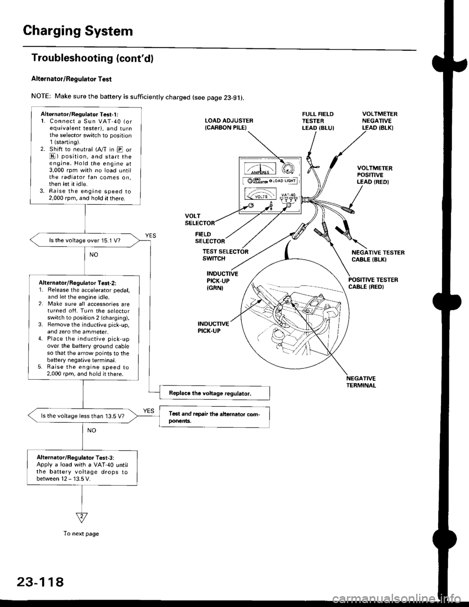
Charging System
Troubleshooting (cont'd)
Alt6rnator/Regulator Test
NOTE: Make sure the baftery is sufficiently charged (see page 23-9j).
FIELDSELECTOR
LOAD AOJUSTER{CARAON PILEI
FULL FIELOTESTERLEAD IBLUI
VOLTMETERNEGATIVELEAD IBLKI
VOLTMETERPOStTtVELEAD (REDI
NEGATIVE TESTERCABLE IBLKI
POSITIVE TESTERCABLE IREDI
TEST SELECTORswrTcH
INDUCTIVEPICK-UP
IGRNI
INDUCNVEPICK.UP
TIVETEBMINAL
Alte.nator/Regulator Test'1 :L Connect a Sun VAT 40 (orequivalent tester), and tu rnthe selector sw;tch to position1(staning).2. Shift to neutral (A/T in E orE) position, and start theengine. Hold the engine at3,000 rpm with no load untilthe radiator fan comes on,then let it idle.3. Raise the engine speed to2,000 rpm, and hold it there.
ls the voltage over 15.1 V?
Alternalor/Regulator Te3t-2:1. Release the accelerator pedal,and let the engine idle.2. Make sure all accessories areturned ofi. Turn the selectorswitch to position 2 (charging).3. Bemove the inductive pick-up,and zero the ammeter,4. Place the inductive pick-upover the battery ground cableso that the arrow points to thebattery negatlve terminal.5. Raise the engine speed to2,000 rpm, and hold it there.
ls the voltage less than 13.5 V?
Alternator/Regulator Test-3:Apply a load with a VAT-40 untilthe battery voltage drops tobetween 12 - 13.5 V.
tffil rCI
[ @lBt* . ,*n 'aHrl
L-;-;l rs-
23-11A
To next page
Page 1589 of 2189
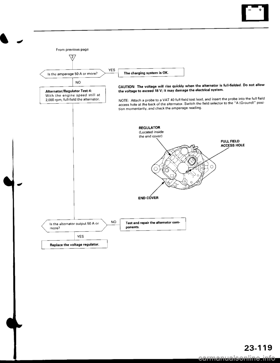
The charging system is OK.ls the amperage 50 A or more?
Alternator/Regulator Test-4:
With the engine sPeed still at
2,000 rpm, fulltieid the alternator.
J
From previous page
CAUTION: The voltage will rise quickly when the allGrnator is flll-fielded Do not ellow
the vollage to exceed 18 V; il may damage the electrical syslem
NOTE: Attach a probe to a VAT 40 full field test lead, and insert the probe into the full field
access hole at the back of the alternator' Switch the field selector to the "A (GroLrnd)" posi
tion momentarilV, and check the amperage readlng
23-119
Page 1590 of 2189
Charging System
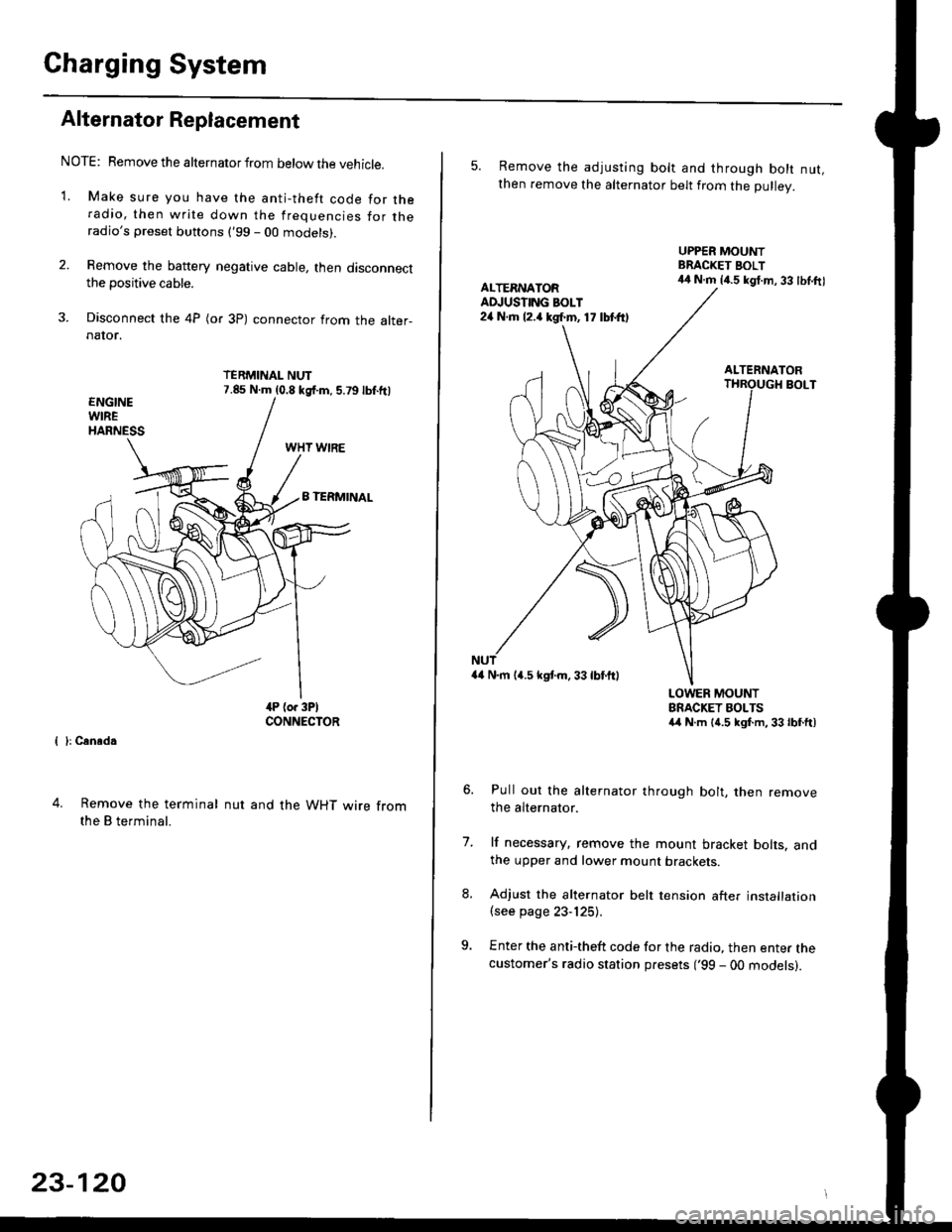
Alternator Replacement
NOTE: Remove the alternator from below the vehicle.
'1. Make sure you have the anti-theft code for theradio, then write down the frequencies for theradio's preset buttons ('99 - 00 models).
2. Remove the battery negative cable, then disconnectthe positive cable.
3. Disconnect the 4P (or 3P) connector from the alter-naIor.
TERMINAL NUT7.85 N.m (0.8 kgf.m, 5.79lbf.ftl
{ }: Cansd.
4. Remove the terminal
the B terminal.
nut and the WHT wire from
23-120
5. Remove the adjusting bolt and through bolt nut,then remove the alternator belt from the Dullev.
UPPER MOUNTBRACKET BOLT44 N.m 14.5 kgt.m, 33 lbl.ftlALTERNATORAD.'USTING BOLT24 N.rh l2.a kgf.m, 17 lbtft)
ALTERNATORBOLT
a4 N.m 14.5 kstm.33lbf'ftl
LOWER MOUNTBRACKET BOLTSa4 N.m l{.5 kgf.m,33lbfft)
Pull out the alternator through bolt, then removethe alternator.
lf necessary, remove the mount bracket bolts. andthe upper and lower mount brackets
Adjust the alternator belt tension after installation(see page 23-125).
Enter the anti-theft code for the radio, then enter thecustomer's radio station presets ('99 - 00 models).
7.
Page 1592 of 2189
Charging System
Rectifier Removal (cont'd)
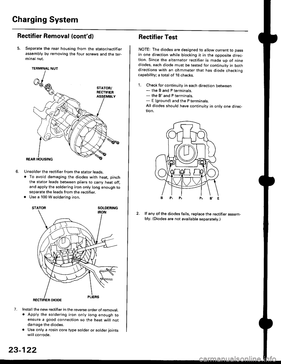
Separate the rear housing from the stator/rectifier
assembly by removing the four screws and the ter-minal nut.
TERMINAL NUT
Unsolder the rectifier from the stator leads,. To avoid damaging the diodes with heat, pinch
the stator leads between pliers to carry heat off,and apply the soldering iron only long enough toseparate the leads from the rectifier.. Use a 100 W soldering iron.
STATOR SOLDERING
7. Install the new rectifier in the reverse order of removal.. Apply the soldering iron only long enough toensure a good connection so the heat will notdamage the diodes.
a Use only a rosin core type solder or solder joints
will corrode.
6.
SOLDERING
23-122
Rectifier Test
NOTE: The diodes are designed to allow current to pass
in one direction while blocking it in the opposite direc-tion. Since the alternator rectifier is made up of ninediodes, each diode must be tested for continuity in bothdirections with an ohmmeter that has diode checkinocapability; a total of 18 checks.
1. Check for continuity in each direction between- the B and P terminals.- the B'and P terminals.- E {ground) and the P terminals.
All diodes should have continuity in only one direc-UOn.
lf any of the diodes fails, replace the rectifier assem-bly, (Diodes are not available separately.)