fog HONDA CIVIC 1999 6.G Workshop Manual
[x] Cancel search | Manufacturer: HONDA, Model Year: 1999, Model line: CIVIC, Model: HONDA CIVIC 1999 6.GPages: 2189, PDF Size: 69.39 MB
Page 78 of 2189
a
a
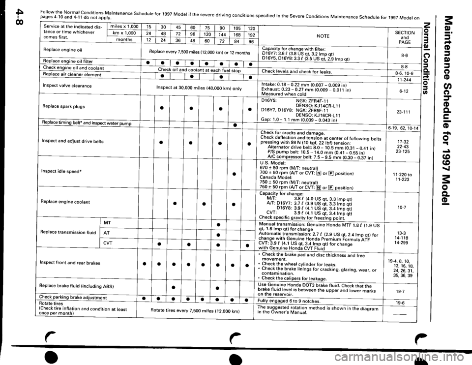
Maintenance Schedule for 1997 Model
Normal Conditions
za.HgEx.?f-
-Ni\j9sXB
oi
!t
*-o-.2
o*E
n
.s
3
.2
E
99
9=
6q6i
zi: Pr
'; -o!
ProGco.
€(o:>at C
Efv
35E
j
I
J
g: li i=:; = =.=-o-r)U- o l':<':@o
qE lHrE:?
; E-l$seggEri izz^29
r! il>6>3 eci,dl : El,Pg i'.1co L: >
;:Et 5 :i
i:;le i il
Eiils E 3l
lo- !
1 ; o.sl
e -EJs: E9 ,;
;5eeF
.f,:=Eo
F.Elq;"
rjYoou?nrP=!P:F 62 9r a
-.-e 33E3 s!EEbei:#3EIFog 6): a6
ii ti"{>
.9 .!
EE
=E =E9| 9i
:b :E
>F b5
F Fi C EE oa9 dE!::2:::66 e;;=fl+ H+r+l(,oo EooiE R(5S P
a?a?a.q o
ri-;tiB fiqqqq Eqq.:.::
,,****'l6c.: e c ll
: >> El
... oo .. 6I
EiF bll
o ol
l- o<
E ^ii> ?nhT ; E€
F ?:b
g ;i:!= Fi F:
,3 I'i +: F
E+ q e;E
PF E E3$
Eee?: e
! ts€:*:
s; E s33q-9EF!
s-;i€di
E}
6-o!Eo
.9 *r:- q; -:3 rb 6
! h; I
I EP ;IF -.4 ;l
r o* c.=lot5.o,6l
E EEE'EEIx 6*x;*l
3 ici EilJ E(J() 6(J'l
!
?
:l
FI6l
=l'il
t-E
E
=
3€
.
-9
ti l.L_dl
6)
:a
EL3:i
ilo
El
El
i f-l
F .l-L l
E
aaaaa
E
N-
-
aaaaaa
aaaaaaaaa
aaaa
aaaaaa
a
a
aaaa
aaaaa
aaa
EE
6o
--l
3
6t 9i I6 =l
EI R I !
;l ; r-l 2 | q'69V
Pt -xt !2 | 2ai ;,91 E I e-t-l
lol
-l
8l -s9t x:l
it :
';/ :
4l P;+t a
g
FFt-ol6Irot
7=
E
E6
:l
E-c
6 d r,l
'?
.s;
it?9
ds3
5
E
i:
aL
6
:
=
.g
.9
:t
.9
;
6
:
i_>
t--
z6
4-A
Page 461 of 2189
ldle Control System
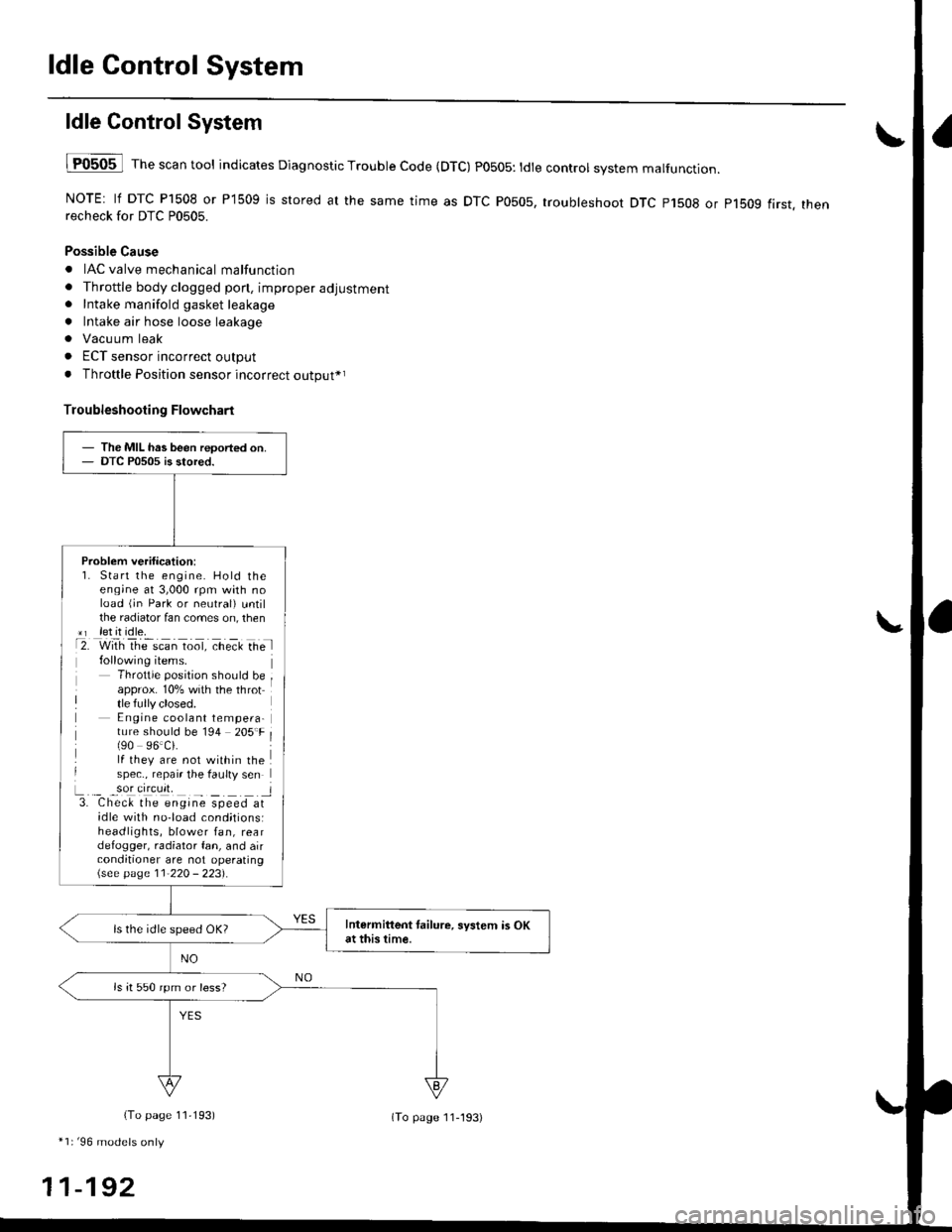
ldle ControlSystem
lF0505 l Th" """n tool indicates Diagnostic Trouble Code (DTC) PO5O5: tdte controt system malfunction.
NOTE: lf DTC P1508 or P1509 is stored at the same time as DTC P0505, troubleshoot DTC p1508 or p1bog first. thenrecheck for DTC P0505.
Possible Cause
. IAC valve mechanical malfunction
. Throttle body clogged pon, improper adjustment. Intake manifold gasket leakage
. Intake air hose loose leakage
. Vacu um leak
. ECT sensor incorrect output
. Throttle Position sensor incorrect output*r
Troubleshooting Flowchart
The MIL has been reoorted on.DTC P0505 is stored.
Problem verification:1. Start the engine. Hold theeng;ne at 3,000 rpm with noload (jn Park or neutral) untilthe radiator fan comes on, then*r let it idle.t2. with rhe scan toot, ct'eit Ge l
Throttle position should beapprox. 10% with the throttle fully closed.E ngine coolant tempera-ture should be 194 205'F(90 96.Ci.lf they are not within thespec., repair the faulty sen
L._ _9oI9[cr]41 l3. Chec& the engine speed atidle with no-load cond;tionsiheadlights, blower fan, reardefogger, radiator fan, and airconditioner are not operating\see page l1-22O - 223).
Intermittent tailure, system is OKat this time.ls the idle speed OK?
ls it 550 rpm or less?
(To page 11,193)
*1r'96 models only
11-192
(To page ll-193)
Page 477 of 2189
ldle Control System
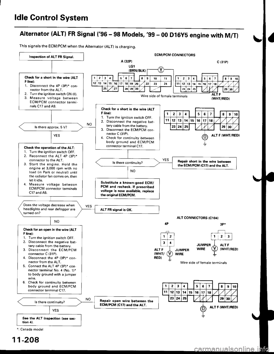
Alternator (ALTI FR Signal {'96 - 98 Models,'99 - 00 Dl6y5 engine with M/Tl
ECM/PCM CONNECTORS
a {32P)
LGl(BRN/BLK)
Wire side of female terminals
ALT CONNECTORS IC1O4I
JUMPER
JUMPER WIRE
WIRE
Wire side of female terminals
ALT F{WHT/REO)
This signals the ECM/PCM when the Alternator (ALT) is charging.
Inspoction of ALT FR Signal.
Check tor a short in tfte wire (ALTF linel:1. oisconnect the 4P (3P)* con-nector from the ALT.2. Turn the ignition switch ON (ll).3. M easu re voltage betweenECM/PCM connector terminals C17 and A9.Check lor a sho.t in the wire {ALTF line):r. I urn rne tgn|lton swtlch ul-f,2. Disconnect the negative bat-tery cable from the baftery.3. Disconnect the ECM/PCM connector C {31P).4. Check for continuity betweenbody ground and ECM/PCMconnector terminal C17.
ls there approx. 5 V?
Check th€ operation of the ALT:1. Turn the ignition switch OFF.2. Reconnect the ALT 4P (3P)*connector to the ALT.3. Start the engine. Hold theengine at 3,000 rpm with noload (in Park or neutral) untjlthe radiator fan comes on, thenlet it idle.4. [,4easu re voltage betweenECM/PCM connector terminalsC17 and A9.
Repair short in the wire betwe€nthe ECM/PCM {Cl71and th€ ALT.
Substitute a known-good ECM/PCM and recheck. It prescribedvoltage is now available, roplacethe originrl ECM/PCM.
Does the voltage decrease whenheadlights and rear defogger areturned on?ALT FR signal is OK.
Check tor an open in the wire (AlTF linel:1. Turn the ignition switch OFF.2. Disconnect the negative bat-tery cable from the battery.3. Disco n nect the ECM/PCMconnector C (31P).4. Disconnect the 4P (3P)* con,nector from the ALT.5. Connect the ALT 4P 13P)l connector terminal No. 4 (No. 1)'to body ground with a iumper
6. Check lor continuity betweenbody ground and ECM/PCMconnector terminal C17,
Repair op6n wire botween th€ECM/PCM (C171rnd th€ ALT.ls there continuity?
c {31P)
1178I10
1112131415161718
232125a30
oALT F IWHT/REDI
4P3P*
1 2l
Flr
rr-ri-frwHr/ (V)
neor Y
*: Canada model
11-208
3I78910
1l1213l415161718/l
232125E30
oALT F IWHT/REDI
Page 489 of 2189
ldle Control System
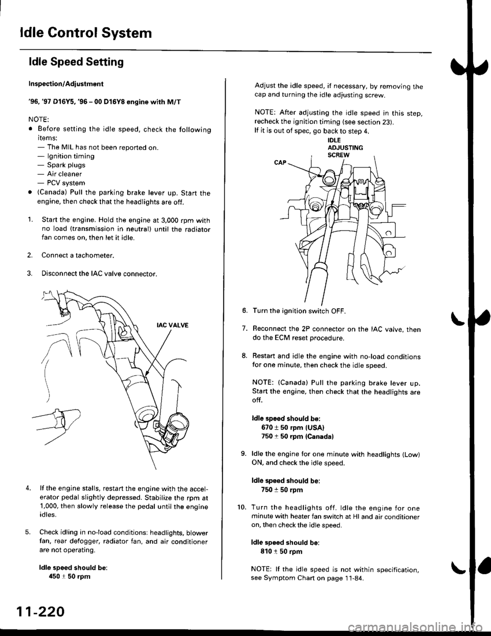
ldle Speed Setting
Inspection/Adiustmenl
'96, '97 Dl6Y5. '96 - 00 Dl5Y8 sngine with M/T
NOTE:
. Before setting the idle speed, check the following
items:- The MIL has not been reported on.- lgnition timing- Spark plugs- Air cleaner- PCV system
o (Canada) Pull the parking brake lever up. Start the
engine, then check that the headlights are off.
1. Start the engine. Hold the engine at 3.000 rpm withno load (taansmission in neutral) until the radiatorfan comes on, then let it idle.
2. Connect a tachometer.
3. Disconnect the IAC valve connector.
4.lf the engine stalls, restart the engine with the accel-
erator pedal slightly depressed. Stabilize the rpm at1,000, then slowly release the pedal until the engineidles.
Check idling in no-load conditionsr headlights. blowerfan. rear defogger, radiator fan, and air conditioner
are not operating.
ldle spsed should be:
450 1 50 rpm
11-220
Adjust the idle speed, if necessary, by removing thecap and turning the idle adjusting screw.
NOTE; After adjusting the idle speed in this step,recheck the ignition timing (see section 23).
lf it is out of spec, go back to step 4.
IDLE
6. Turn the ignition switch OFF.
7. Reconnect the 2P connector on the IAC valve, then
do the ECM reset procedure.
8. Restart and idle the engine with no-load conditionsfor one minute, then check the idle speed.
NOTE: (Canada) Pull the parking brake lever up.Start the engine, then check that the headlights areoff.
ldle sp€sd should b€:
670 i 50 rpm IUSA)750 t 50 rpm {Canada}
9. ldle the engine tor one minute with headlights {Low)ON. and check the idle speed.
ldle speed should be:
750 :r 50 rpm
10. Turn the headlights off. ldle the engine for oneminute with heater fan switch at Hl and air conditioneron, then check the idle speed.
ldle speed should be:
810150 rpm
NOTE: lf the idle speed is not within specification,see Symptom Chan on page 11-84.
Page 490 of 2189
t
t
I
'96.'97 D16Y5 engine with CVT,'96 - 00 D16Y8 ongins
with A/T and'96 - 00 Dl6Y7 €ngine
Adiust the idle speed using a Honda PGM Tester if pos-
sible. lf not, use the following procedure:
NOTEI
. Leave the IAC valve connected
. Betore setting the idle speed. check the following
items:- The MIL has not been reported on'
- lgnition timing
- Spark Plugs- Air cleaner- PCV system
1. Connect a tachometer.
2. Start the engine. Hold the engine at 3,000 rpm wirh
no load (in Park or neutral) until the radiator fan
comes on, then let it idle.
3. Check the idle speed with no-load conditions: head-
iights, blower fan, rear defogger, radiator fan, and
air conditioner are not operatlng
ldl€ spoed should be:
USA:
D16Y5 engine with CVT, D16Y7 engine with A/T'
Dl6YB engine with A/T:
700 :r 50 rpm (in E or El Positionl
D16Y7 engine with M/T:
670 i 50 rpm
Canada:
Dl6Y8 sngin€, Dl6Y7 engins:
M/T750 t 50 rpm
NT750 1 50 rpm (in E or El Position)
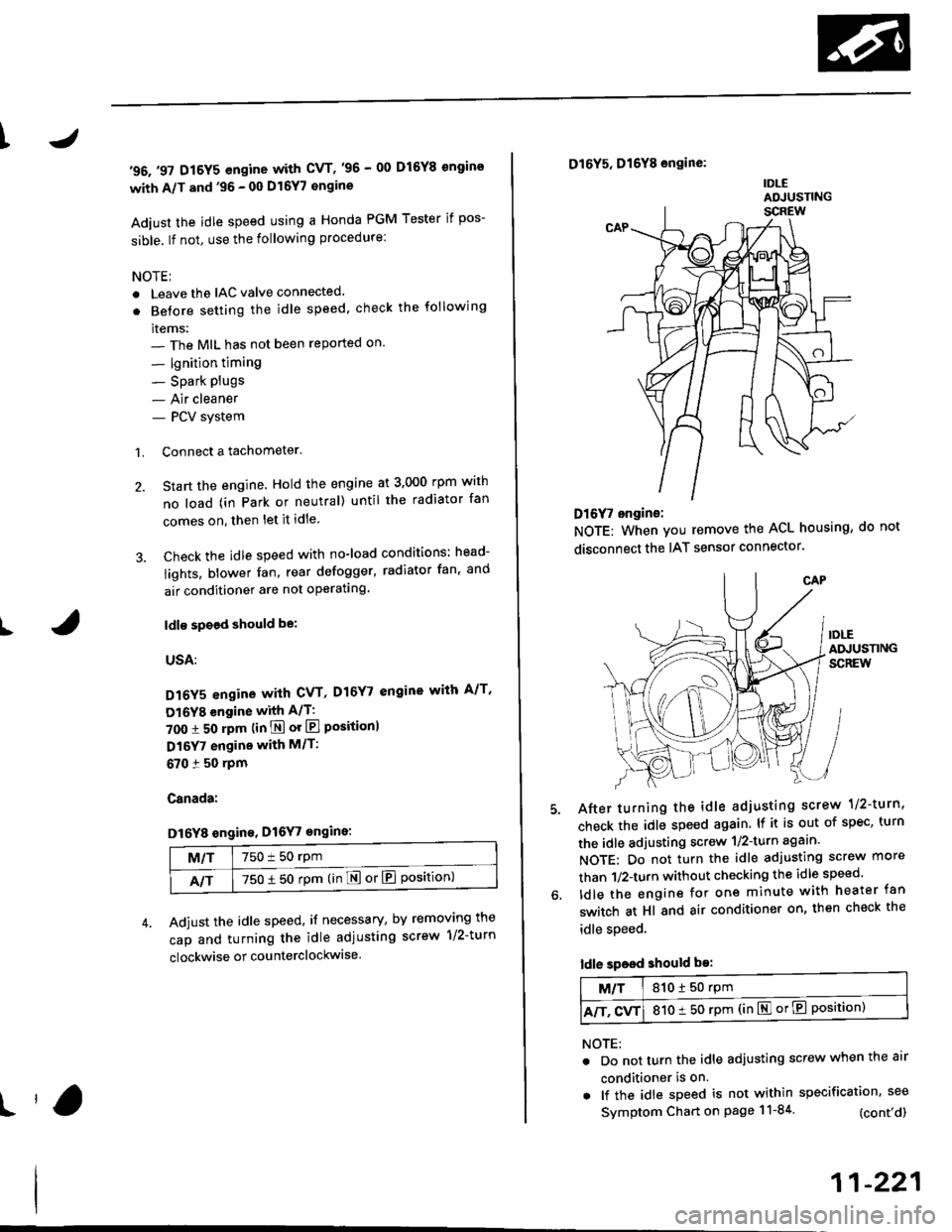
Adjust the idle speed, if necessary, by removing the
cap and turning the idle adiusting screw 1/2-turn
clockwise or counterclockwise
D16Y5, D16Y8 engine:
IDLEADJUSTING
Dl6f, ongine:
NOTE: When you remove the ACL housing, do not
disconnect the IAT sensor connector
After turning the idle adjusting scrow 1/2-turn'
check the idle speed again. lf it is out of spec, turn
the idle adjusting screw 1/2-turn agaan'
NOTE: Do not turn the idle adjusting screw more
than 1/2-turn without checking the idle speed'
ldle the engine for one minute with heater fan
switch at Hl and air conditioner on, then check the
idle speed.
ldle speed should be:
M/T810150 rpm
A/T. CvT810 t 50 rpm (in El or E Position)
NOTE:
. Do not turn the idle adjusting screw when the air
conditioner is on.
. lf the idle speed is not within specification. see
Symptom Chart on page 11-84 (cont'd)
11-221
Page 491 of 2189
ldle Control System
ldle Speed Setting (cont'dl
Inspeqtion/Adiustment
38 D16Y5 engine whh M/T,'99 - 00 81642 engine
NOTE: Before setting the idle speed, check the follow-ing items;- The MIL has not been reported on.- lgnition timing- Spark plugs- Air cleaner- PCV system
'1. Start the engine. Hold the engine at 3,000 rpm withno load (transmission in neutral) until the radiatorfan comes on, then let it idle.
Connect a tachometer.
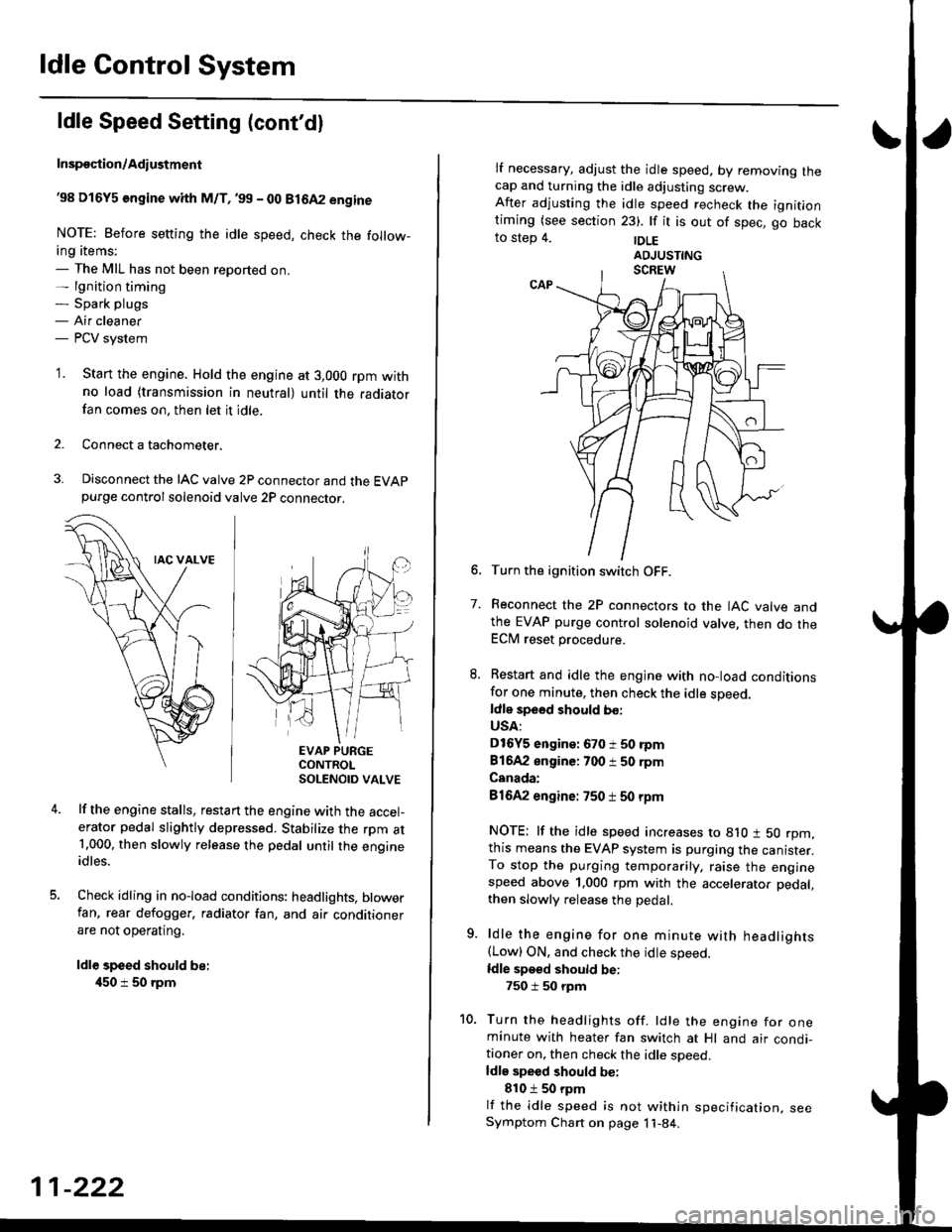
Disconnect the IAC valve 2P connector and the EVAPpurge controlsolenoid valve 2P connector.
EVAP PURGECONTROLSOLENOID VALVE
lf the engine stalls, restart the engine with the accel-erator pedal slightly depressed. Stabilize the rpm at1.000, then slowly release the pedal until the engineidles.
Check idling in no-load conditions: headlights, blowerfan, rear defogger, radiator fan, and air conditionerare not operating.
ldl€ speed should be:
450 i 50 rpm
11-222
lf necessary, adjust the idle speed, by removrng lnecap and turning the idle adjusting screw.After adjusting the idle speed recheck the ignitlontiming (see section 23). lf it is out of spec, go backto step 4. |DLE
6. Turn the ignition switch OFF.
7. Reconnect the 2P connectors to the IAC valve andthe EVAP purge control solenoid valve, then do theECM reset procedure.
8. Restart and idle the engine with no-load conditionsfor one minute, then check the idle sDeed.ldle speed should bo:
USA:
D16Y5 engine: 670 i 50 rpm
81642 engine: 700 i 50 rpm
Canada:
81642 engine: 750 t 50 rpm
NOTE: lf the idle speed increases to 8lO t 50 rpm,this means the EVAP system is purging the canister.To stop the purging temporarily, raise the enginespeed above 1,000 rpm with the accelerator pedal,
then slowly release the pedal.
9. ldle the engine for one minute with headlights(Low) ON. and check the idle speed.
ldle speed should be:
750 i 50 rpm
10. Turn the headlights off. ldle the engine for oneminute with heater fan switch at Hl and air condi-tioner on, then check the idle soeed.ldls speed should be:
810 t 50 rpm
lf the idle speed is not within specification, seeSymptom Chart on page 11-84.
Page 492 of 2189

\
I
'98 - 0O D16Y5 ongine with CvT
Adjust the idle speed using a Honda PGM Tester if pos-
sible. lf not, use the following procedure:
NOTE:
. Leave the IAC valve connected.
. Before s€tting the idle speed, check the following
rtems:- The MIL has not been reported on.
- lgnition timing
- Spark Plugs- Air clean€r
- PCV svstem
'1. Connect a tachometer.
2. Stan the engine. Hold the engine at 3,000 rpm w'th
no load (transmission in E or E] position) until the
radiator Jan comes on, then let it idle.
3. Check the idle speed under no-load conditions:
head lights, blower fan, rear defogger, radiator fan,
and air conditioner are not operatlng.
ldlo spaod ehould bo: 700 t 50 rpm
. lf the idle speed is within the specification, the
procedure is comPlete.
. lf the idle sDeed is out of specitication, 9o to step 4'
4. tf the idle speed is 810 1 50 rpm, this means the
EVAP system is purging the canister. To stop the
purging temporarily, raise the engine speed above
l,OO0 rgm with the accelsrator pedal. Slowly release
the pedal. and rscheck the idl€ speed.
. tf the idle speed is within the specificstion, the
Drocedure is comPlete.
. lf the idle sp€ed is out of spocification, go to step 5.
5. Disconnect th€ EVAP purgs control solenoid valve
2P connector.
EVAP PURGECONTROL
6. Remove the cap and turn the idle adiusting screw
1/2-turn clockwise or counterclockwlse
IDLE
7.After turning the idle adjusting screw 1/2-turn, check
the idl€ speed again. lf it is out of spec, turn the idle
adjusting screw 1/2-turn again.
NOTE: Do not turn the idle adjusting screw more
than 1/2-turn without checking the idle speed.
Turn the ignition switch OFF. Reconnect the EVAP
purge control solenoid valve 2P connector' then do
the ECM reset Procedure.
Start the engine. ldle the engine for one minute with
heater fan switch at Hl and air conditioner on, then
check the idle speed.
ldle spaed should be:
810 t 50 rpm (in El or E Posiiion)
lf the idle speed is not within specification, see
Svmptom Chart on Page 11-84.
9.
SOLENOID VALVE
11-223
Page 521 of 2189
Emission Gontrol System
System Description
The emission control system includes a Three Way Cata-lytic Convener (TWC), Exhaust Gas Recirculation (EGR)
system,. Positive Crankcase Ventilation (pCV) system andEvaporative Emission (EVAP) Control system. The emis-sion control system is designed to meet federal and stateemission standards.*: D16Y5 engine
Tailpipe Emission
Inspestion
@@ Do not smoke during ihis procedure. Keepany open flame away from your work area.
1. Start the engine. Hold the engine at 3,000 rpm withno load (in Park or neutral) until the radiator fancomes on. then let it idle.
2. Connect a tachometer.
Check and, if necessary, adjust the idle speed (see
page 11-220 - 223).
Warm up and calibrate the CO meter according to themeter manufacturer's instructions.
Check idle CO with the headlights, heater blower,rear window defogger, cooling fan, and air condition-er off.
NOTE: (Canada) Pull the parking brake lever up.Start the engine, then check that the headlights areoff.
CO mete. should indicate 0.1% maximum.
NOTE: '98 Dl6Y5 engine - lf the idle speed incress-es to 8101 50 rpm, this means the EVAp system ispurging the canister. To stop the purging temporari-ly. raise the engine speed above 1,000 rpm with theaccelerator pedal, then slowly release the pedal.
11-252
eFORWARD -
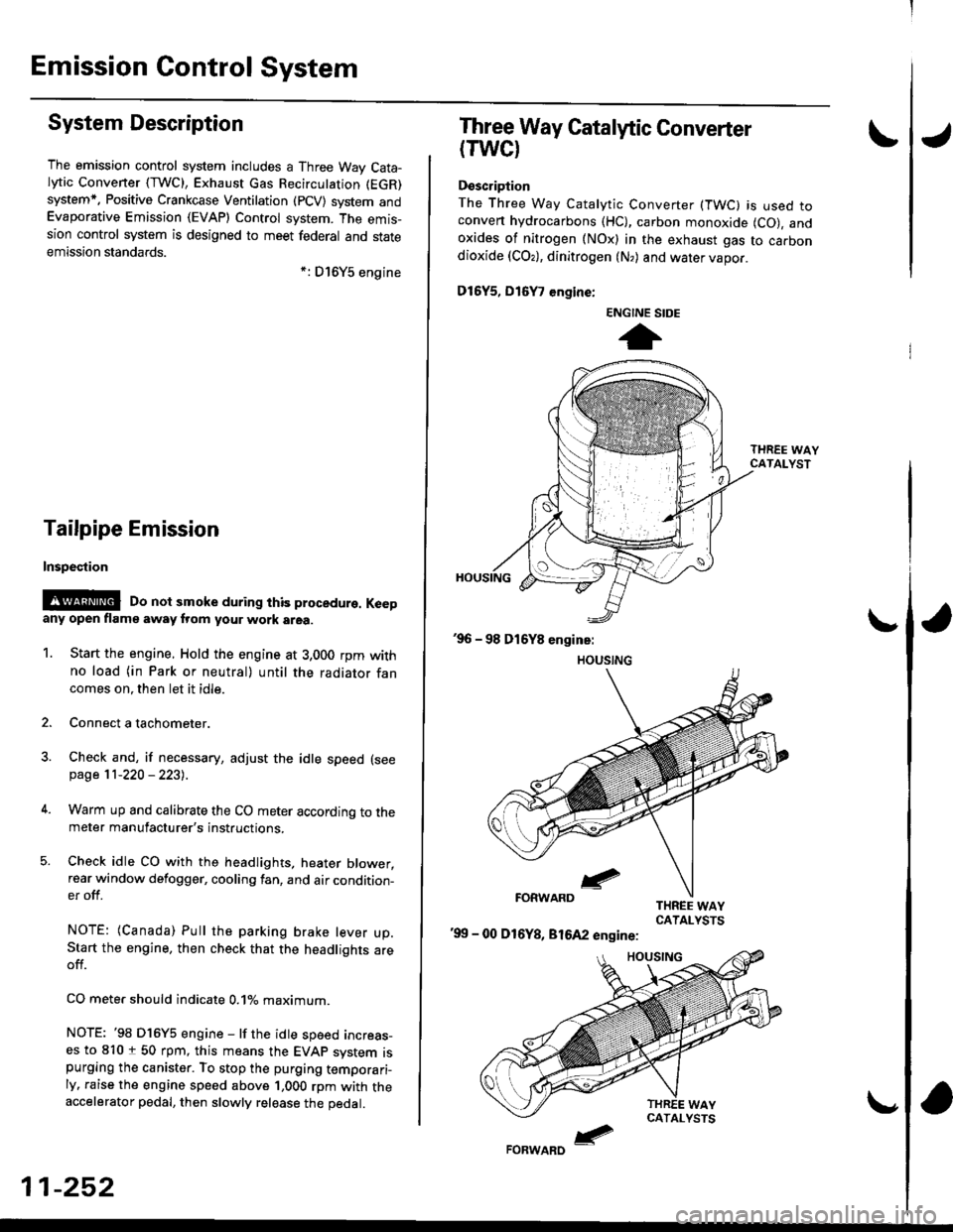
Three Way Catalytic Converter
(TWCI
Doscription
The Three Way Catalytic Converter (TWC) is used toconven hydrocarbons (HC), carbon monoxide (CO), andoxides of nitrogen (NOx) in the exhaust gas to carbondioxide (COr), dinitrogen (N,) and water vapor.
D15Y5, D16
, engine:
'99 - 00 D16Y8, 81642 engine:
ENGINE SIDE
t
Page 548 of 2189
 39 - 0O Dl6Y5 ongins")
\
Fue| Tank Pr€ssure sensor 196 Dr6Y8 engine (coupe},,97 D16Y7 angino (coupo: KL mode|' 3edan: KL (Lxl modg||',97
Dl6Y8 engine (coupe: all modeb, sedan: Ki model.'98'all modols) 39 - 0O Dl6Y5 ongins with M/Tl:
rFoG'l::;Jl"too|indicatesDiagnosticTroub|ecode(oTc)P0453;Ahighvo|tageprob|emintheFue|TankPressure
ECM/PCM CONNECTOR D Il6PI
PTANKILT GRNI
\
Wire side of tgmale torminals
FUEL TANKPRESSURE SENSOR3P CONNECTOR (C792)
vcc2(YEL/BLU}
sG2(GRN/BLKI
Wire sid€ of female terminals
I
sG2IGRN/BLKI
PTANKIGBN/RED}
(cont'd)
11-279
The MIL has beon reponed on
DTC P0453 b stored.
Check the vacuum lines:
Check the vacuum lines oI the
fueltank pressure sensor for mis-
routing, leakage, breakage and
clogging.
Are the vacuum lines OK?
Problem verification:1. Do the ECM/PCM Reset Proce-
dure.2. Femove the fuel fill cap
3. Turn the ignition switch oN (ll).
4. Monitor the FTP Sensor volt-
age with the Honda PGM
Tester, or measure voltage
between bodY ground and
ECM/PCM connector termrnal
D15.
lntormittont t iluro, 3Ystem is OK
at this time. Check lot Poor con_
noctiona or loo3e wirat at C131
{loc.ted undor right 3id6 of d8hl,
CaOl llocatod rbov. under-dalh
fus6/relay boxl, C574 (C568lr
llocatod und6l accoss Pan6ll,C792 lfuel tank Preasulo aonlorl
end ECM/PCM.
ls there approx. 2 5 V?
Check for an oPen in the wire(SG2line):1. Turn the ignition switch OFF.
2. Reinstall the fuellill cap
3. Disconnect the fuel tank Pres-sure sensor 3P connector.
4. Turn the ignition switch ON (ll)
5. Measure voltage between the
fuel tank Pressure sensor 3P
connector terminals No. 1 and
No.2.
Ropair opon in the wira b€tw€sn
the fuel tank prasure sonlor and
ECM/PCM (Dl1).ls there aPProx. 5 V?
Check for an open in the wire(PTANK line):Measure voltage between the
fueltank Pressure sensor 3P con-
nector No. 3 terminal and No. 2
termrnal,
ls there approx. 5 V?
*: coupe
{To page 11-280)
Page 1262 of 2189
Rear Window
Removal
2DllDl
CAUTION:
. Put on gloves to protect your hands.
. Uso ssat covers to avoid damaging any surlaces,. Do not damage thg roar window dofogggr grid linss,
window antenna grid lines, and tsrminalg.
1. To remove the rear window, first remove the:. Trunk lid
. Rear seat cushion (see pages 20-79, 81). Rear seat side bolsters {4D, see page 20-79). Rear seat-back (2D, see page 20-81)
. Rear shelf {see pages 20-59, 61}
. Rear pillar trim {4D, see page 20-59). Side trim panel (2D, see page 20-61)
. Ouarter trim panel (2D, see page 20-61)
. Rear roof trim (see page 20-65)
2, Disconnect the rear window defogger connector
from each side.
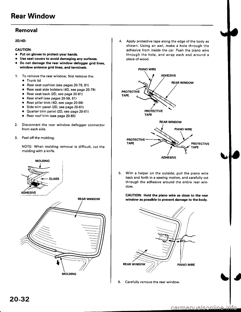
3. Peel off the molding.
NOTE: When molding removal is difficult, cut the
molding with a knile.
F"*t,
MOLDING
ID_HESI.VE ---, ,/,/
REAR WINDOW
S
MOLDING
20-32
PIANO WIRE
4. Apply protective tape along the edge of the body as
shown. Using an awl, make a hole through the
adhesive from inside the car. Push the piano wire
through the hole, and wrap each end around apiece of wood.
ADHESIVE
REAR WINDOW
PROTECTIVETAPE
TAPE
REAR WNDOW
PIANO WIRE
PROTECTIVETAPE
With a helper on the outside, pull the piano wire
back and forth in a sawing motion, and carefully cut
through the adhesive around the entire rear win-
dow.
CAUTION: Hold the piano wiro as close to the rear
window as possibls to prcyent damage to the body.
6. Carefullv remove the rear window.
ADHESIVE