lock-up control solenoid resistance 12 HONDA CIVIC 1999 6.G Workshop Manual
[x] Cancel search | Manufacturer: HONDA, Model Year: 1999, Model line: CIVIC, Model: HONDA CIVIC 1999 6.GPages: 2189, PDF Size: 69.39 MB
Page 734 of 2189
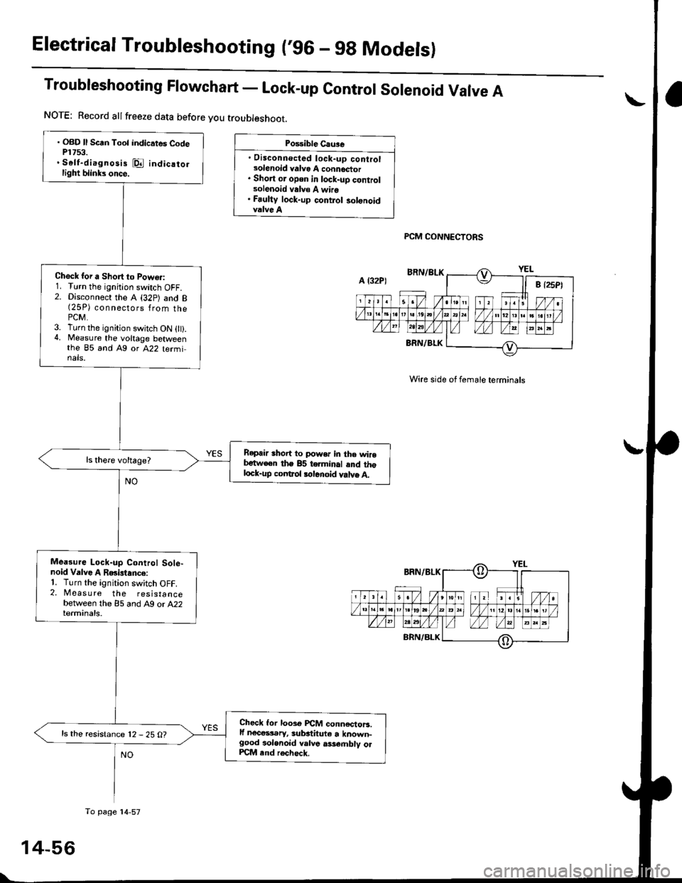
Electrical Troubleshooting (,96 - gg Models)
Troubleshooting Flowchart - Lock-up contror sorenoid Varve A
Po$ible Cau3e
. Disconnecled lock-up controlsolenoid valvo A connector. Short or open in lock-uD controlsolenoid valv€ A wire. Fauliy lock-up contlol solonoidvalve A
PCM CONNECTORS
Wire side of female terminals
. OBD ll Scrn Toot indicates CodeP1753.. Self-diagnosis @ indicatorlight blinks once.
Check for a Short to Powo.:1. Turn the ignition switch OFF.2. Disconnect the A (32p) and B(25P) connsgl6ps 1rq- thaPCM.3. Turn the ignition swjtch ON 0t).4, Measure the voltage betweenthe 85 and Ag or A22 terminals.
Repair shoit to power in the wirebetw€en the 85 terminal and thglock-up coDtrol tolenoid valve A.
Mea3ure Lock-up Control Sole-noid Valve A RGislance:'1. Turn the ignition switch OFF.2. Measure the resistancebetween the 85 and A9 or A22terminals.
Check lor looso PCM conn€ctoB.lf nece$.ry, substituto a known-good aolonoid valve ass€.nblv olPCM end rech6ck.
ls the resistance 12 - 25 O?
NOTE: Record allfreeze data before you troubleshoot.
A l32P)
To page'14-57
Page 735 of 2189
From page 14-56
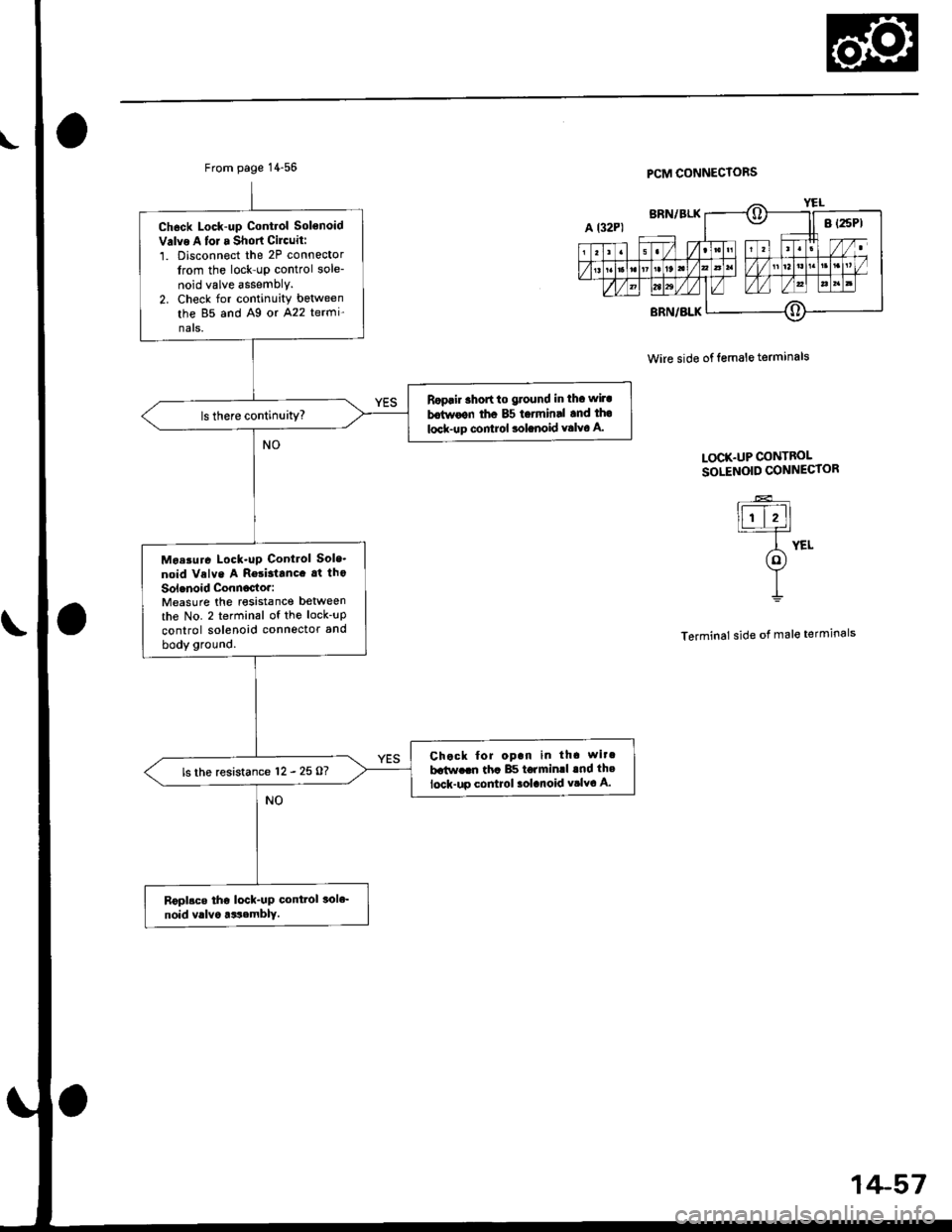
Ch6ck Lock-up Control Solenoid
Valve A tor a Short Cilcuiti
1. Disconnect the 2P connector
lrom the lock-up control sole-
noid valve assemblY.2. Check for continuity between
the 85 and Ag or A22 termi-
nats.
Ropair 3hort to giound in iha wila
b.twoqn th6 85 terminrl rnd tho
locl-up control 3olanoid valvo A.
Mo..ura Lock-up Control Sole'
noid Velve A Reri3tanc. at tho
Solenoid Conn6cto.:Measure the resistance betweenthe No. 2 terminal of the lock-up
control solenoid connector and
body ground.
Chock for opan in tha wit.
ba(w.an tha 85 torminll lnd the
lock-uo control lolanoid vtlYa A.ls the resistance 12 _ 25 O?
Roplsce tho lock"up cont.ol 3ol€_
noid vllvo arsembly.
PCM CONNECIOBS
Wire side of lem6leterminals
LOCK.UP CONTROLSOrINOID CONNECTOR
YEL
Teaminal side of malo terminals
lml-,f
(o)
I
14-57
Page 736 of 2189
Electrical Troubleshooting ('96 - 9g Modelsl
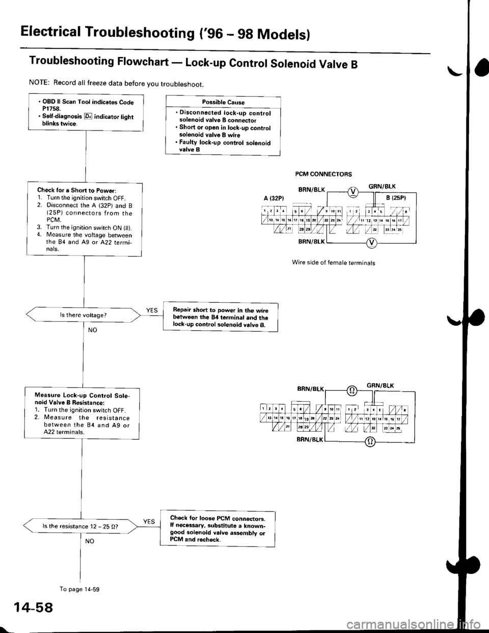
Troubleshooting Ftowchart - Lock-up control sorenoid Varve B
Possible Cause
. Disconnected lock-up controlsolenoid valve B connector' Short or open in lock-up controlsolonoid valve B whe. Faulty lock-up control solenoidvalve B
PCM CONNECTORS
Wire side of female terminals
. OBD ll Scan Tool indicrtes CodeP1758.. Self-diagnosis E indicrtor lightblinkstwice.
Check for a Shon to Power:1. Turn the ignition switch OFF.2. Disconnect the A (32p) and B(25P) connectors from thePCM,3. Turn the ignition switch ON t).4. Measure the voltage betweenthe 84 and A9 or A22 termi-nals.
Repeir short to power in the wirebetween the 84 teiminal and thelock-up control solenoid valve B.
Moasure Lock-up Control Sole-noid Valve B Resistance:1. Turn the ignition switch OFF.2. Measure the resistancebetween the 84 and Ag orA22 terminals.
Check for loose FCM connectors,lf necessary, substitute a known-good solenoid valve assembly olP1CM and rech6ck.
ls the resistance 12 - 25 O?
NOTE: Record all freeze data before you troubleshoot.
A {32P)
To page 14-59
t-
Page 737 of 2189

From page 14 58
Check Lock-up Control Solenoid
Valve B for a Short Circuh:
1. Disconnect the 2P connector
from the lock-uP control sole'
noid valve assefibly.
2. Check for continuity between
the 84 and A9 or A22 terma-
nals,
Rgprir 3hort to ground in tho wite
Hwoon the 84 torminal and the
lock-uo contlol solonoid valvs B.ls there continuity?
Measu.o Lock-uP Control Sole'
noid Valve I Resistance at tho
Solenoid Connector:Measure the resistance between
the No. 1 terminal o{ the lock-up
control solenoid connector and
body ground.
Chcck tor opcn in the wirs
b€tlve.n the 84 ierminal and tho
lock-up conttol solonoid vllvc B.ls the resistance 12 - 25 O?
Reolace the lock'up control sole-
noid valve assemblY.
PCM CONNECTORS
Wire side oI lemale terminals
LOCK.UP CONTROL
SOLENOID CONNECTOR
IFl;II-r:-]
6nn/eLKfi
I
Terminal sido ot male terminals
14-59
Page 758 of 2189
Electrical Troubleshooting ('99 - 00 Models)
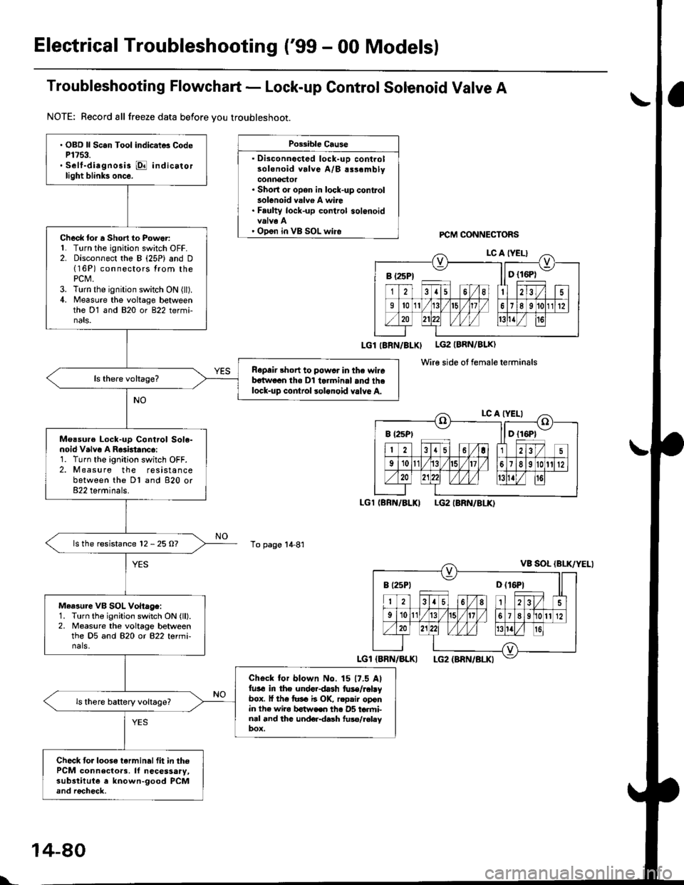
Troubleshooting Flowchart - Lock-up Control Solenoid Valve A
NOTE: Record all freeze data before vou troubleshoot.
Possible Cause
. Disconnocted lock-uD controlsolenoid valve A/B alsemblyconnector. Short or opon in lock-up conkolsolenoid valv6 A wire. Faulty lock-up control solenoidvalva A' Open in VB SOL wireFCM CONNECTORS
LGl IBRN/BLXI LG2 (BRN/BLK)
Wire side ot female terminals
LGl (BRN/BLKILG2 IBRN/8LK)
To page 1+81
a\
. OBD ll Scan Tool indic.t6 CodeP1753.. Self-diagnosis @ indicatorlight blink3 once.
Check lor a Short to Power:L Turn the ignition switch OFF.2. Disconnect the B (25P) and D(16P) connectors lrom thePCt\4.3. Turn the ignition switch ON (ll).4. Measure the voltage betweenthe Dl and 820 or 822 termi-nats.
Ropair short to powcr in the wirebstwoon tho Dl tolminal and thelock-up cor|lrol lolonoid valvo A.
Measu.e Lock-up Cont.ol Sole-noid V.lvo A R63btanc6:1. Turn the ignition switch OFF.2. Measure the resistancebetween the Dl and 820 or822 terminals.
ls the resistance 12 - 25 O?
Measure VB SOL Vohage:1. Turn the ignition switch ON (ll).2. Measure the voltage betweenthe D5 and 820 or 822 termi-nals.
Check for blown No. 15 17.5 Alfu3€ in the undordash fuse/rabybox. l{ th€ tusa ii OK, r.pair oponin the wira b€twoen th€ 05 torfti-nal and thc und€r{ash fuso/r€laybox.
Check to.loose tarminalfit in thePCM connecloa3. ll necessary,substilute a known-good PCMand rocheck.
B (25Pt ll D {16P1
B (2sPt ll D {16P1
I t25Pt D (16P1
l..
14-80
Page 759 of 2189

From page 14-80
Check lor continuity between the
820 terminal and body ground,
and between the B22 terminal
and body ground.
Ropair opon in thc wircs betwe6n
the 820 lnd 822 tolminals .ndground {G10ll, and tepair Poolground (G10'l).
Check Lock-up Cont.ol Solonoidvalve A for a Shon Cilcuit:1. Disconnect the 2P connectortrom the lock-up control sole-
noid valve ry'B assembly.
2. Check for continuity betlv€en
th6 D1 and 820 or 822 termi-
nals.
R6p.ir 3hort to glound in thc
wir. b.two.n the Dl torn|in.l
ard th. lock-up conttol iol.noid
valva A.
Maasuro Lock-up Control Sol.-
noid Vllve A Ro.istance at tho
Solanoid Conn6ctor:Measure the resistance between
the No. 2 terminal of the lock-up
control solenoid valve y'y'B assem-
bly connector and body ground.
R6placo tho lock-up control solo_
noid valve A/B.$6mblY.ls the resistance '12 - 25 O?
Chack for opon in tho wiro
botweon the Dl t..minal and tho
lock-up control solenoid Yalva A.
PCM CONNECTOR B {25P}
I.G1 (BRN/BLKI
Wire side of l6male terminals
PCM OONI{ECTORS
Wire side ot female terminals
LOCK.UP CO TROL SOTINOID VALVEA/B ASSEMBLY CON]TECTOR I2P}
]F]ALr-f-
I LC A {YEu
(o)Y
I
Terminal side of male terminals
B (25p) ll o l16P)
IBRN/BLK} LG2IBRN/BLK}
14-A1
Page 760 of 2189
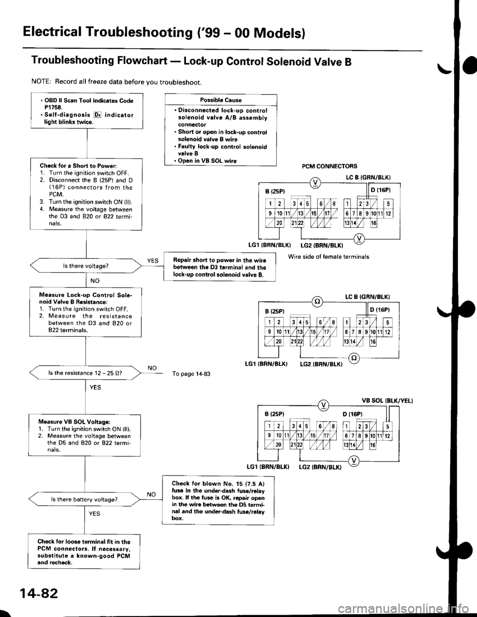
Electrical Troubleshooting ('99 - 00 Models)
Troubleshooting Flowchart - Lock-up Control Solenoid Valve B
NOTE| Record allfreeze data before you troubleshoot.
Possibla Cause
. Oisconnected lock-uD controlsolenoid velve A/B assemblyconnector. Short or open in lock-up controlsolenoid valv€ B wire. Faulty lock-up control solenoidvalve B' Open in VB SOL wirercM CONNECTORS
To page 14-83
' OBD ll Scan Tool indic.tes CodeP1758.. Self-diagnosis E indicatorlight blinks twice.
Chack for a Short to Power:1. Turn the ignition switch OFF.2. Disconnect the I (25P) and D(16P) connectors from thePCM.3. lurn the ignition switch ON (ll).4. Measure the voltage betweenthe D3 and 820 ot 822 tetmi-nals,
Repair short to power in the wirebetween the D3 terminal and thelock-up contlol solenoid valve B.
Measure Lock-up Control Sole-noid Vdlve I R8i3tance:1. Turn the ignition switch OFF.2, Measure the resistancebetween the D3 and 820 or822 terminals.
ls the resistance 12 - 25 O?
Measure VB SOL Voltago:1. Turn the ignition switch ON lll).2. Measure the voltage betweenthe D5 and 820 or 822 termi-nals.
Check for blown No. 15 {7.5 Alfus€ in the under-dash luse/releybox. It the fuse is OK, repair openin the wir6 between th6 DS terminal and the under-dash fuse/rebyoox,
ls there battery voltage?
Chock for loose te.minal fit in thePCM connectors. It necessary,substitute a known-good PCMend recheck.
B t2sP) ll D t15P)
Wire side ol female terminals
I {2sPt ll D (16Pt
B (25P1 D t16Pt
\
14-82
Page 761 of 2189
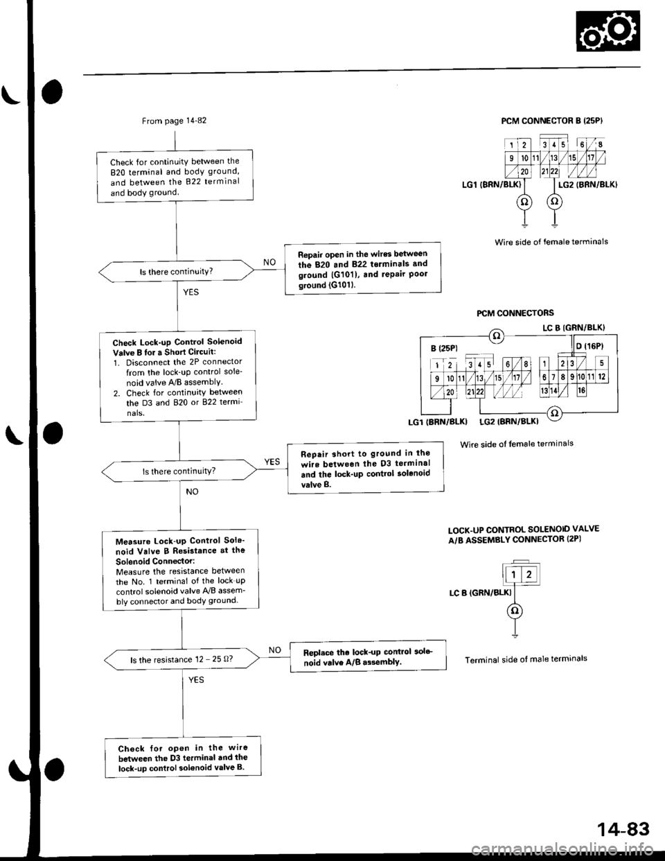
From page 14-82
Check for continuitY between the
820 terminal and body ground,
and between the 822 terminal
and body ground
Repair open in the wires between
the 820 and 822 terminals and
ground |G101), and repair Poolground (G1011.
Check Lock-up Control Solenoid
Valve B lor a Short Cilcuit:
1. Disconnect the 2P connector
from the lock_uP control sole-
noid vaive A/B assemblY.
2. Check for continuity between
the D3 and 820 or 822 termi
nals.
Rep.ir short to ground in lho
wire between lhe D3 terminal
and the lock-up contlol solenoid
valve B.
Measure Lock-up Control Sol6'
noid Valve B Resistance at the
Sol6noid Conn€ctor:Measure the resistance between
the No. 1 terminal of the lock uP
control solenoid valve A'lB assem_
bly connector and body ground-
Repl.ce the lock-up control 3olc
noid valve A/B a$emblY.ls the resistance 12 - 25 0?
Ch6ck {or open in the wire
between the D3 terminal dnd ihe
lock-up control sol€noid valve B.
PCM CONNECTOR B (25PI
LG1 (BRN/BLK)
2351 6I
l011/15
LG2
oo
(BRN/BLKI
Wire side of female terminals
Wire side of female terminals
LOCK.UP CONTROL SOLENOID VALVE
A/B ASSEMBLY CONNECTOR (2PI
t;TJllt z!]4
LC B (GRN/BLKI It(o)
YI
Terminal side of male termrnals
B (25P1 - llo t16Pt
14-83
Page 783 of 2189
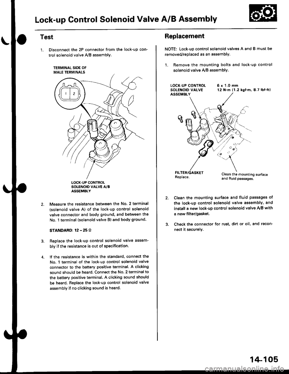
Lock-up Gontrol Solenoid Valve A/B Assembly
Test
'1, Disconnect the 2P connector from the
trol solenoid valve 1y'8 assembly.
TERMINAL SIOE OF
MALE TERMINALS
tocK-up con-
LOCK.UP CONTROLSOLENOID VALVE A/BASSEMBLY
Measure the resistance between the No. 2 terminal
(solenoid valve A) of the lock-up control solenoid
valve connector and body ground, and between the
No. 1 terminal (solenoid valve Bl and body ground.
STANDARD: 12 - 25 O
Replace the lock-up control solenoid valve assem-
bly if the resistance is out of specification.
lf the resistance is within the standard, connect the
No. 1 terminal of the lock-up control solenoid valve
connector to the battery positive terminal. A clicking
sound should be heard. Connsct the No. 2 terminal to
the battery positive terminal. A clicking sound should
be heard. Replace the lock-up control solenoid valve
assembly if no clicking sound is heard.
Replacement
NOTE: Lock-up control solenoid valves A and I must bs
removed/replaced as an assembly.
1. Remove the mounting bolts and lock-up control
solenoid valve Ay'B assemblv.
6 r 1.0 mm12 N.m (1.2 kgf.m,8.7 lbl.ftl
/:'-
Clean the mounting surfaceand fluid psssages.
Clean the mounting surface and fluid passages of
th6 lock-up control solenoid valve assembly, and
instsll a new lock-up control sol€noid valve Ay'B with
a new filtsr/gask€t.
Check the connector for rust, dirt or oil, and racon-
nect it securely.
1+105