throttle HONDA CIVIC 1999 6.G Workshop Manual
[x] Cancel search | Manufacturer: HONDA, Model Year: 1999, Model line: CIVIC, Model: HONDA CIVIC 1999 6.GPages: 2189, PDF Size: 69.39 MB
Page 48 of 2189
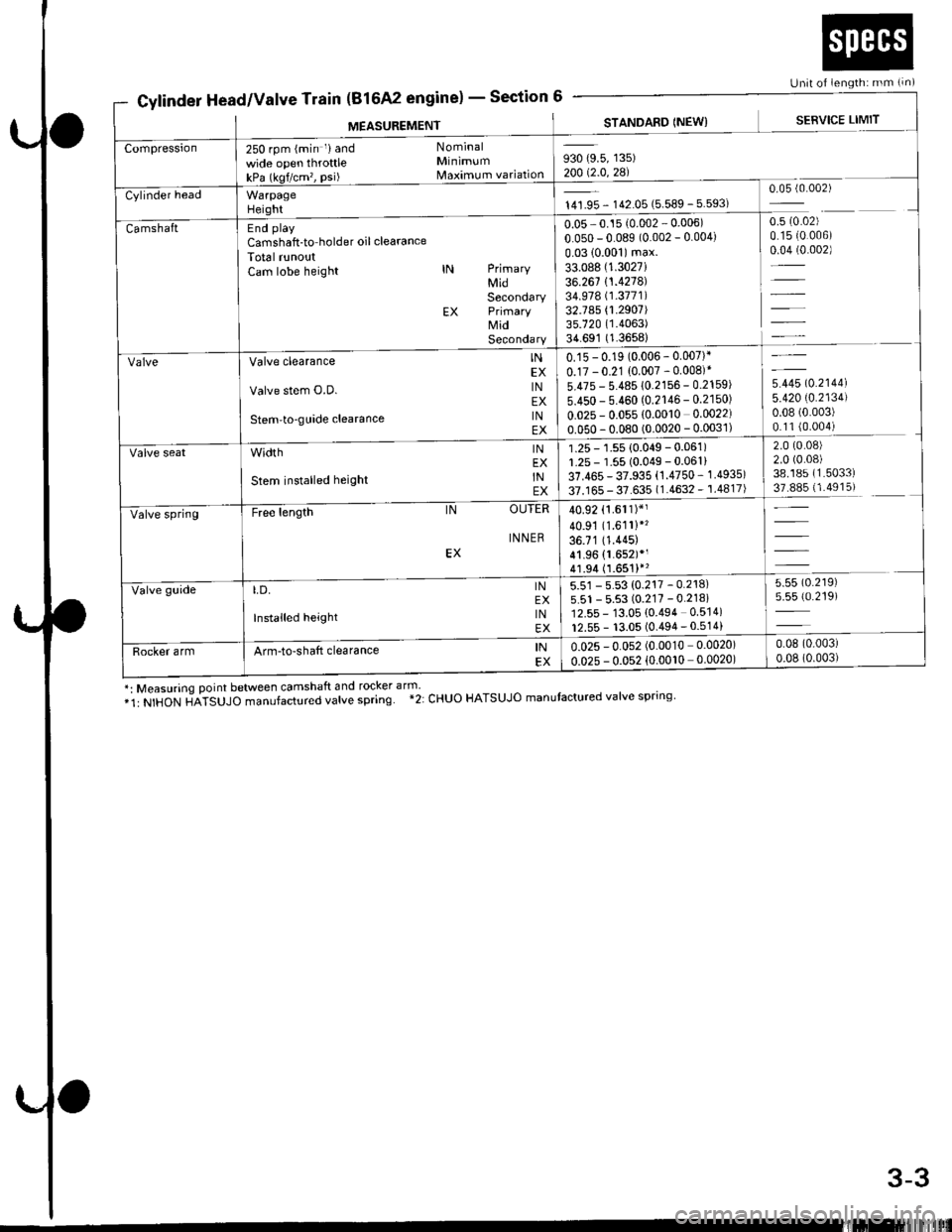
Unit of iength: mm (!n)
930 (9.5, 135)20012.0,zal
0.05 - 0.15 (0.002 - 0.006)
0.050 - 0.089 (0.002 - 0.004)
0.0310.001)max.33.088 (1.3027i
36.261 {1.4278)34.978 (1.3771)
32.785 {1.2907)35.720 (1.4063)
34.691 (1.3658)
u*u lo.r,ool5.420 (0.2134)
0.08 (0.003)
0.11 (0.004)
2.0 (0.08)
2.0 (0.08)
38.185 (1.5033)
37.885 (1.4915)
250 rpm (min riand Nominal
wide open throttle Minimum
kPa (kqf/cm'�, psi) Maximum variation
End play
Camshaft-to holder oil clea€nce
Total runoutCam lobe height lN PrimaryMidSecondaryEX PrimaryMidSecondary
0.15 - 0.19 (0.006 - 0.007)*
0.17 - 0.21 (0.007 - 0.008)*
5.475 - 5.485 10.2156 - 0.2159)
5.450 - 5.460 (0.2146 - 0.2150)
0.025 - 0.055 (0.0010 0.0022)
0.050-0.080 (0.0020 - 0.0031)
Valve clearance
Valve stem O.D.
Stem-to-guide clearance
INEXINEXINEX
1.25 - 1.55 {0.049 - 0.061)r.25 - 1.55 (0.049 - 0.061)
37.465 - 37.935 (1.4750 - 1.4935)
37.165 - 37.635 (1.4632 - 1.4817)
INEXINEX
width
Stem installed height
40.92 (1.611)*'
40.91 (1.6111"
36.71 (1.415)
41.96 (1.652)*r
4 r.94 (1.651)*'
free t*gth lN OUTER
5.51 - 5.53 (0.217 - 0.218)5.51 - 5.53 (0.217 - 0.218i12.55 - 13.05 (0.494 0.5'�j4)
12.55 - 13.05 (0.494 - 0.514)
LD. lNEX
Installed height lNEX
0.025 - 0.052 (0.0010 0.0020)
o.o2s - 0.052 {0.0010 0.0020)
Cylinder Head/Valve Train(816A2 engine) - Section
MEASUREMENTSTANDARD INEW)SERVICE LIMIT
*: Measuring point between camshaft and rocker arm'*1: NTHON H;TSUJO manufactured vatve spring. *2: CHUO HATSUJO manutactured valve spnng.
3-3
Page 72 of 2189
ILubrication Points
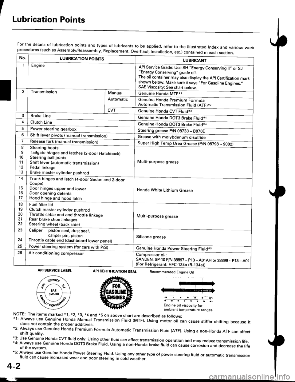
For the details of lubrication points and types of lubricants to be applied, refer to the lllustrated Index and various workprocedures (such as Assembly/Reassembly, Replacement, Overhaul. Installation, etc.) contained in each section.
No.LUBRICATION POINTS
Engine
LUBRICANT
"Energy Conserving" grade oil,The oil container may also display the Apl Certification markshown below. Make sure it says ,,For Gasoline Engines.,,SAE Viscosity: See chart below,
I
TransmissionManualGenuine Honda MTF*1
Genuine Honda Premium FormulaAutomatic Transmission Fluid (ATF)*,
Genuine Honda CVT Fluid*3
Genuine Honda DOT3 Brake Fluid*a
Automatic
CVT
3Brake Line
ClL,tci t""e4
I
Genuine Honda DOT3 Brake Fluid*aPower steering gearboxSteering grease P/N 08733 - BO70EShift lever pivots (manual transmission)Grease with molybdenum disulfide7-:ti
9
10'l'l
l3
14
't7
18
19
20
2122
Release fork (manual trancmi
Shift lever (automatic transmission)Pedal linkageBrake master cylinder pushrod
Super High Temp Urea crease (p/N 08798 - 9OO2)
i Multi-purpose grease
I
I
Honda White Lithium Grease
Multi-purpose grease
Silicone grease
@
Trunk hinges and latch (4-door Sedan and 2-doorCoupe)Door hinges upper and lowerDoor opening detentsHood hinge and hood latch-FUet T ter ttd
Clutch master cylinder pushrodThrottle cable end and throttle linkageRear brake shoe linkagesSteering wheel (back side)
23
E-
Caliper piston seal, dust seal,caliper pin. pistonThrottle cable end (dashboard lower panel)
Power steering system (for cars with p/S)
Air conditioning compressorComDressor oil:SANDEN: SPlo P/N 38897 - p13 -A01AH or 38899 - p13_ A01{For Refrigerant: HFC-134a (R-134a))
CERTIFICATION SEAL
ffi
NorE: The items m arked * 1, *2, +3, *4 and +5 on above chan are described as folows:*1: Always use Genuine Honda Manual Transmission Fluid (MTF). Using motor oil can cause stiffer shifting because itdoes not contain the proper additives.*2: Always use Genuine Honda premium Formula Automatic Transmission Fluid (ATF). Using a non-Honda ATF can affectshift quality.+3: Use Genuine Honda cVTfluid only usingotherfluid can affect tra nsmission operation and may reduce transmission life.*4: Always use Genuine Honda DoT3 Brake Fluid. Using a non-Honda brake fluid can cause corrosion and dec.ease the lifeof the svstem.*5: Always use Genuine Honda Power steering Fluid. using any other type of power steering fluid or automatrc transmissionfluid can cause increased wear and poor steering in cold weather.
4-2
Recommended Engine Oil
Engine oil viscosity forambrent temperature ranges
API SERVICE LABEL
Page 99 of 2189
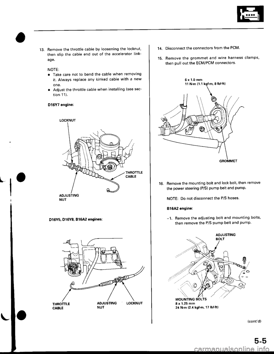
13. Remove the throftle cable by loosening the locknut,
then slip the cable end out of the accelerator link-
age.
NOTE;
. Take care not to bend the cable when removing
it. Always replace any kinked cable with a new
one.
. Adjust the throttle cable when installing (see sec-
tion 1 1).
D16Y7 engine:
D16Y5, D16Y8, B16A2 engines:
LOCKNUT
LOCKNUT
14,Disconnect the connectors from the PCM.
Remove the grommet and wire harness clamps,
then pull out the ECM/PCM connectors
6x1.0mm
16. Remove the mounting bolt and lock bolt, then remove
the power steering (P/S) pump belt and pump
NOTE: Do not disconnect the P/S hoses.
816A2 engine:
Remove the adjusting bolt and mounting boits,
then remove the P/S pump belt and pump
(cont'd)
5-5
AOJUSTING
Page 110 of 2189
Engine Removal/lnstallation
Installation (cont'd)
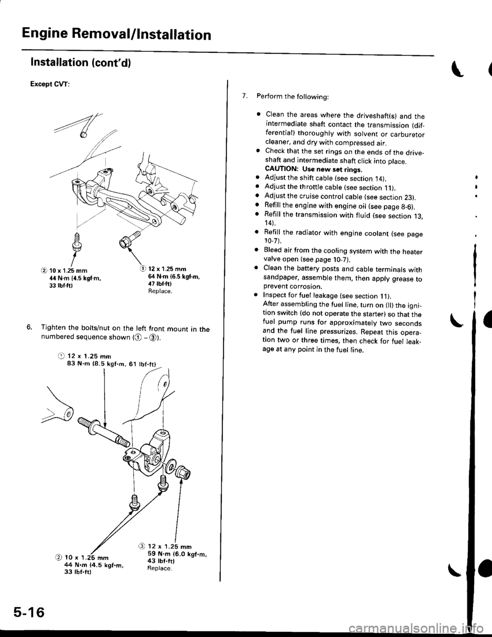
Except CVT:
12 x 1.25 mm64 N.m (6.5 kgd.m,
Tighten the bolts/nut on the left front mount in thenumbered sequence shown {O - @).
(t 12 x 1.25 mm83 N'm (8.5 kgf.m,61 tbt.trl
/+4 N.m 14.5 kgf.m,33 lbt.trl
O 12 r 1.25 mm59 N.m 16.0 kgt.m,43 tbt.rtlSeplace.
5-16
\
7. Perform the following:
. Clean the areas where the driveshaft(s) and theintermediate shaft contact the transmission (dif_ferential) thoroughly with solvent or carburetorcteaner, and dry with compressed air.. Check that the set rings on the ends of the drive_shaft and intermediate shaft click into place.CAUTION: Use new set rings,. Adjust the shift cable (see section 14).. Adjust the throttle cable (see section 11).. Adjust the cruise control cable (see section 23).. Refill the engine with engine oil (see page 8-6).. Refill the transmission with fluid (see section 13,14).
. Refill the radiator with engine coolant (see page10-7).
. Bleed air from the cooling system with the heatervalve open (see page j0-7).
. Clean the battery posts and cable terminals withsandpaper, assemble them, then apply grease toprevent corrosaon.. Inspect for fuel leakage (see section j l).After assembling the fuel line, turn on l) the igni_tion switch (do not operate the starter) so that thefuel pump runs for approximately two secondsand the fuel line pressurizes. Repeat this opera_taon two or three times, then check for fuel leak_age at any point in the fuel line,
Page 138 of 2189
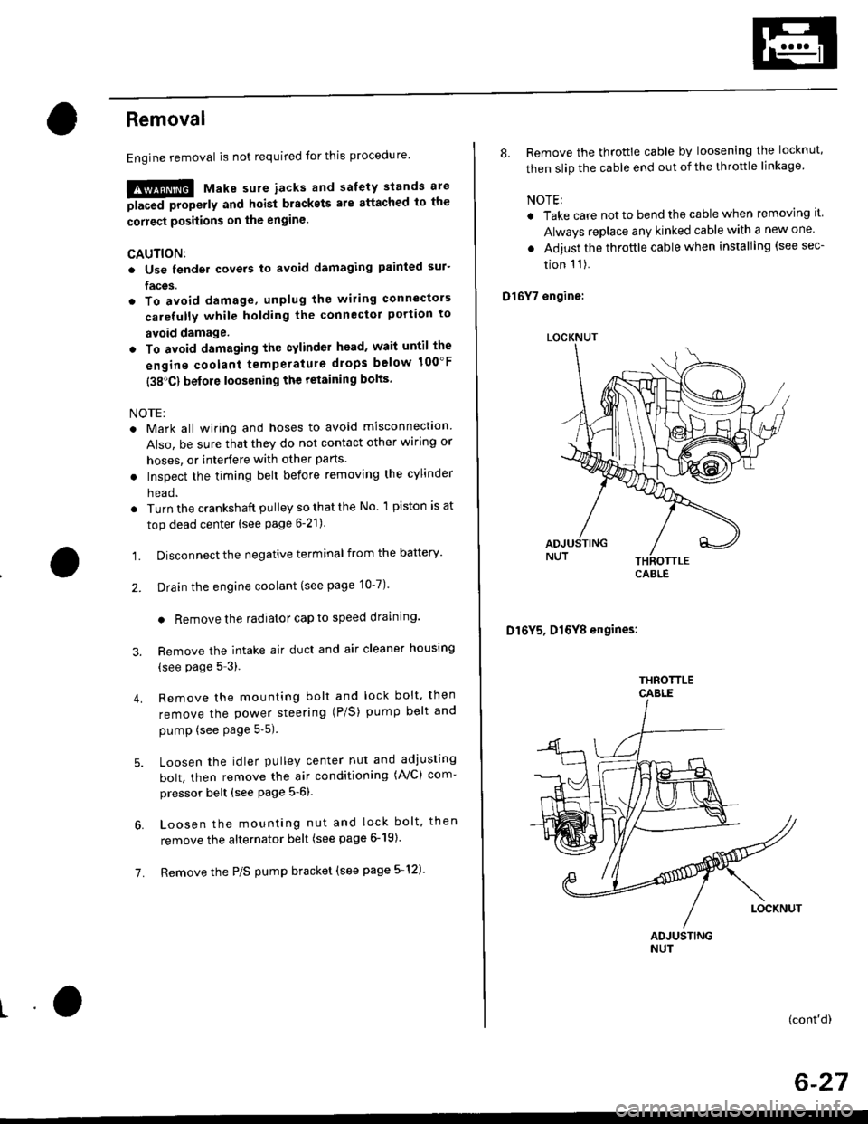
Removal
Engine removal is not required for this procedure
!!!s@ Make sure iacks and salety stands are
f ta"eata"ea propetty and hoist brackets are attached to the
correct positions on the engine.
CAUTION:
. Use tender covels to avoid damaging painted sul-
faces.
o To avoid damage, unplug the wiling connectors
carefully while holding the connector portion to
avoid damage.
. To avoid damaging the cylinder head, wait until the
engine coolant temperature drops below 100"F
{38"C} before loossning the tetaining bolts.
NOTE:
o Mark all wiring and hoses to avoid misconnectlon
Also, be sure that they do not contact other wiring or
hoses, or interfere with other parts.
. Inspect the timing belt before removing the cylinder
h ead.
. Turnthe crankshaft pu lley so that the No. lpistonisat
top dead center (see Page 6-21)
'1. Disconnect the negative terminal from the battery'
Drain the engine coolant (see page'10-7).
a Remove the radiator cap to speed draining.
Remove the intake air duct and air cleaner housing
(see page 5 3).
Remove the mounting bolt and lock bolt. then
remove the power steering (P/S) pump belt and
pump (see page 5'5).
Loosen the idler pulley center nut and adjusting
bolt' then remove the air conditioning (A'lc) com-
pressor belt (see Page 5-6).
Loosen the mounting nut and lock bolt. then
remove the alternator belt (see page 6-19).
Remove the P/S pump bracket (see page 5-12).
3.
4.
2.
6.
1.
8. Remove the throttle cable by loosening the locknut,
then slip the cable end out of the throttle linkage
NOTE:
. Take care not to bend the cable when removing it
Always replace any kinked cable with a new one
. Adjust the throttle cable when installing (see sec-
tion 1 1).
D16Y7 engine:
Dl6Y5, Dl6Y8 engines:
THFOTTLECABLE
(cont'd)
6-27
LOCKNUT
CABLE
Page 140 of 2189
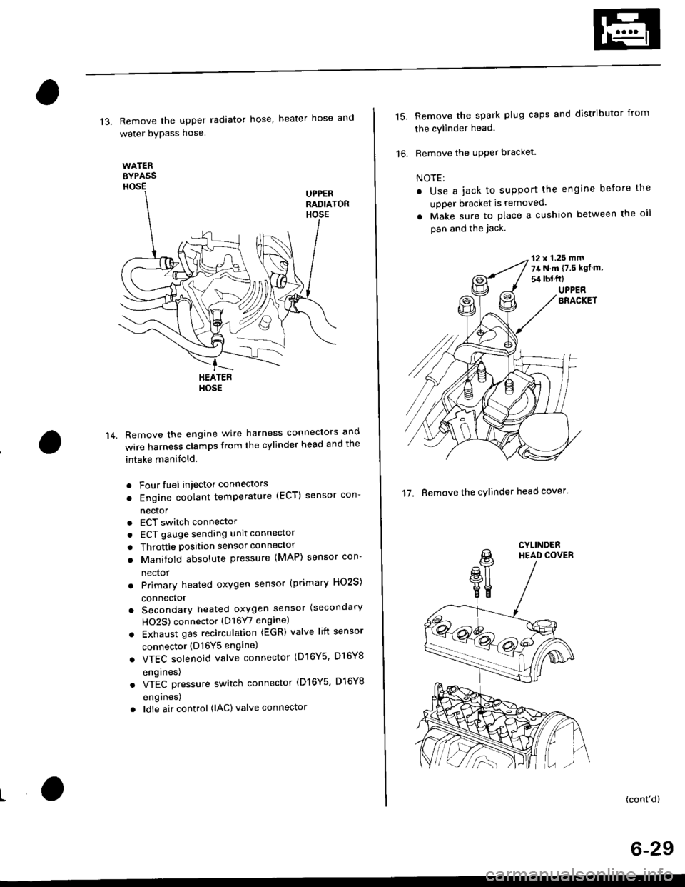
13. Remove the upper radiator hose' heater hose and
water bYPass hose
WATEREYPASSHOSEUPPERRADIATORHOSE
14.
HEATERHOSE
Remove the engine wire harness connectors and
wire harness clamps from the cylinder head and the
intake manifold.
o Four fuel injector connectors
. Engine coolant temperature (ECT) sensor con-
nector
a
a
a
ECT switch connector
ECT gauge sending unit connector
Throttle position sensor connector
Manitold absolute pressure (MAP) sensor con-
nector
Primary heated oxygen sensor (primary HO2S)
connector
Secondary heated oxygen sensor (secondary
HO2S) connector (D16Y7 engine)
Exhaust gas recirculation (EGR) valve lift sensor
connector (D16Y5 engine)
. VTEC solenoid valve connector (Dl6Y5, D16Y8
engrnes)
. VTEC pressure switch connector (D16Y5. D16Y8
engrnes,
. ldle air control (lAC) valve connector
15.Remove the spark plug caps and distributor from
the cylinder head.
Remove the uPPer bracket.
NOTE:
. Use a jack to support the engine before the
upper bracket is removed.
. Make sure to place a cushion between the oil
pan and the jack.
12 x 1.25 mm
74 N.m {7.5 kgf m.
sil lbl.ftl
UPPERBRACKET
'17. Remove the cylinder head cover'
CYLINDERHEAD COVER
(cont'd)
6-29
Page 178 of 2189
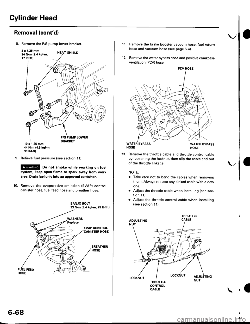
Cylinder Head
Removal (cont'd)
8. Remove the P/S pump lower bracket.
8 x 1.25 mm24 N.m 12.4 kgf.m,17 tbtftl
9.
T SHIELD
10.
P/S PUMP LOWERBRACKET10 x 1.25 mm44 N.m {4.5 kgf.m,33 tbf.frl
Relieve fuel pressure (see section l1).
@ Do not smok6 while working on fuel
system, keep open flam€ or spark away lrom work
ar€a, Drain fuelonly into an approved cortain€r.
Remove the evaporative emission (EVAP) control
canister hose, fuel feed hose and breather hose.
BANJO BOLT33 N.m (3.4 kgl.m.25 lbf.ftl
BREATHERHOSE
WASHERS
6-68
\.
11. Remove the brake booster vacuum hose, fuel return
hose and vacuum hose (see page 5 4).
12. Remove the water bypass hose and positive crankcase
ventilation (PCV) hose.
WATER BYPASSHOSEWATER EYPASSHOSE
Remove the throttle cable and throttle control cable
by loosening the locknut, then slip the cable end out
of the throftle linkage.
NOTE;
. Take care not to bend the cables when removing
them. Always replace any kinked cable with a new
one.
. Adjust the throttle cable when installing (see sec-
tion I I ),. Adjust the throttle control cable when installing(see section 14).
CONTROLCABLE
1a
PCV HOSE
Page 179 of 2189
WATER BYPASS
HOSE
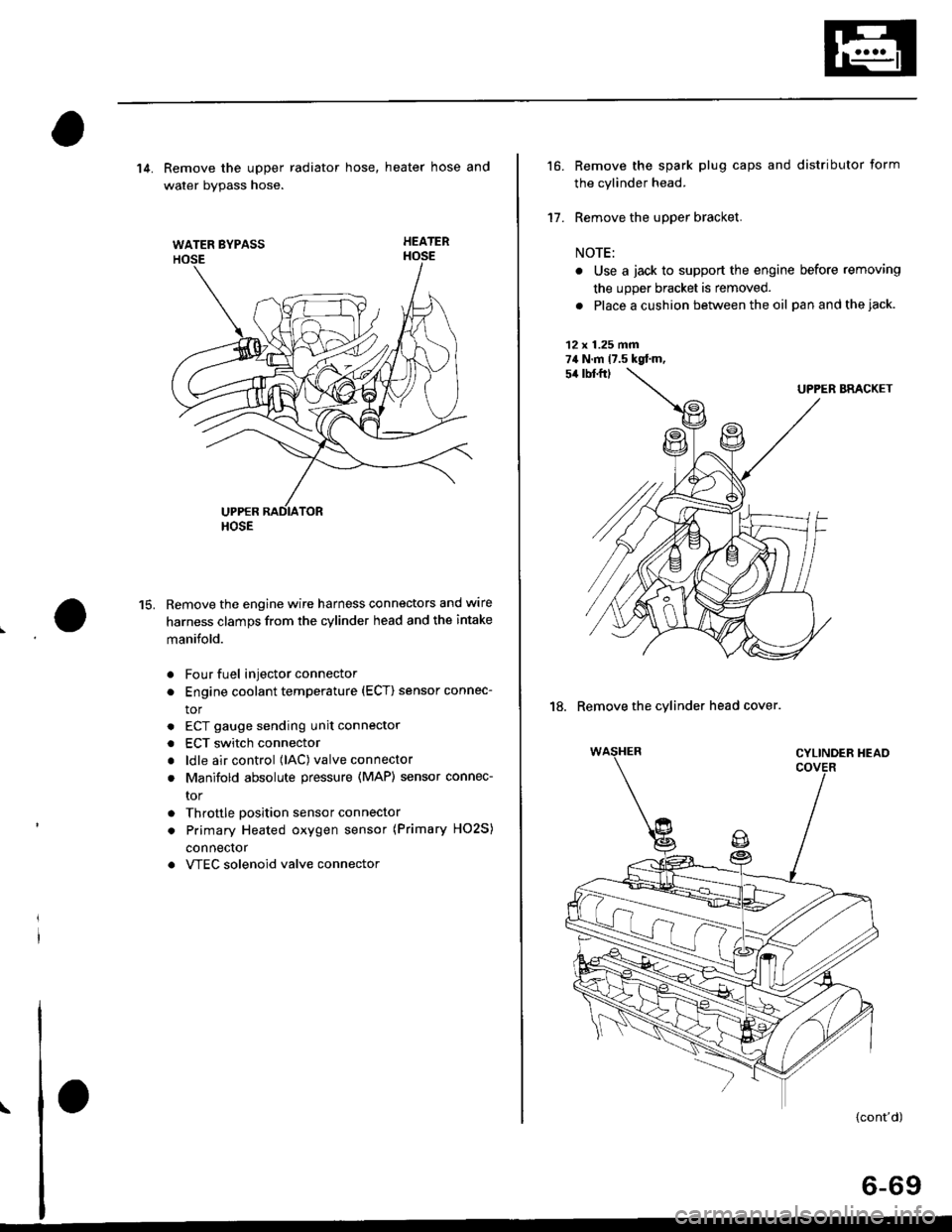
14. Remove the upper radiator hose, heater hose and
water bvpass hose.
HEATER
Remove the engine wire harness connectors and wlre
harness clamps from the cylinder head and the intake
manifold.
Four fuel injector connector
Engine coolant temperature (ECT) sensor connec-
tor
ECT gauge sending unit connector
ECT switch connector
ldle air control (lAC) valve connector
Manifold absolute pressure (MAP) sensor connec-
tor
Throttle position sensor connector
Primary Heated oxygen sensor (Primary HO2S)
connecror
VTEC solenoid valve connector
15.
a
a
a
a
a
\
16.
17.
Remove the spark plug caps and distributor form
the cylinder head.
Remove the upper bracket.
NOTE:
. Use a jack to support the engine before removing
the upp€r bracket is removed.
. Place a cushion between the oil panandthejack.
12 x 1.25 fin74 N.m 17.5 kgtm,
UPPER BRACKET
18. Remove the cylinder head cover.
{cont'd)
6-69
Page 245 of 2189
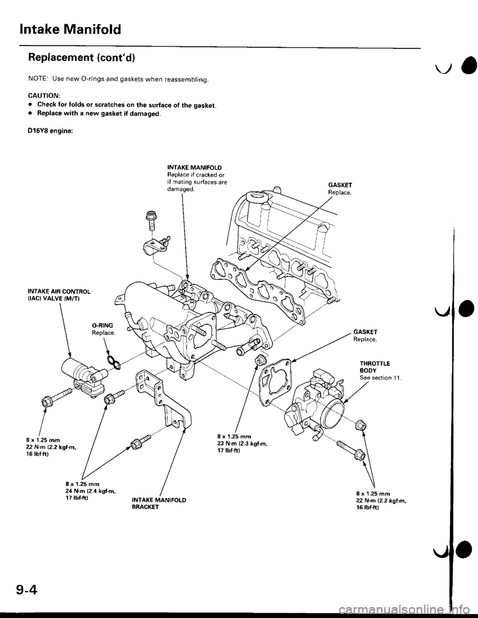
lntake Manifold
Replacement (cont'dl
NOTE: Use new O,rings and gaskets when reassembling.
CAUTION:
. Check lor folds or scratches on the surface of the gasket.. Replace with a new gasket il damaged.
D16Y8 engine:
INTAKE MANIFOLDReplace if cracked orif mating surfaces areoamageo,
INTAKE AIR CONTROL{ract vAt_vE {M/Tl
GASKETReplace.
8 x 1.25 mm24 N.m {2.{ kgtm.17 tbtftt
THROTTLEBODY
8 x 1.25 mm22 N.rn |.2.2 kgl.rn,16 tbtft)INTAKE MANIFOLDBRACKET
9-4
Page 270 of 2189

!
Fuel and Emrsslons
SoecialToofs .....,...."..,. 11-2
Component Locations
lndex ....................., ......... 11-3
Svstem Description
Vacuum Connections ................,,..,.. ......... 11-12
Electrical Connections ...............,.,.,... ....... 11-29
System Connectors ........,.,.,.......................... 1 1-51
Troubleshooting
Troubleshooting Procedures ................. .. 11-81
Engine Control Module/PowertrainControl Module TerminalAfiangement ....,.,..... 11-88
Diagnostic Trouble Code Chart .................,., 11.97
How to Read Flowcharts .,.......................... . 11-103
PGM-Fl System
System Description ...... 11-10,1
Troubleshooting Flowcharts
Engine Control Module/PowertrainContlol Module ........ 11-107
Manitold Absolute Pressure Sensor .....'. . ... 11-115
fntake Air Temperatuie Sensor ..... . . ., . 11'121
Engine Coolant Temperatuae Sensol ........., 11-128
Throttle Position Sensor ...................,........... 11-132
Primary Heated Orygen Sensor (Sensor 1l ... 11-139
Secondary Heated Oxygen Sensor(Sensor 21.................................................... 1 1-153
Heated Oxygen Sensor Heater ...................,. 11-157
Fuel Supply System ...... 11-164
Random Mislire ......., ..11-166
Misfire Detected in One Cylindsr ................. 11-167
Knock Sensor .,.,............ 11-170
CKP/TDC/CYP Sensor ................................... 11'172
Vehicle Speed Sensor ...........,......,...,.,........... 1t-176
Barometric Pressure Sensor ...............,......... I 1-178
Electrical Load Detector,.,,............................ 1 1-179
CKF Sensor .................... 11-183
ECM/PCM Internal Circuit ............................. I 1-188
A/T Signal {TMA/TMBI .................................. I 1-189
ldle Control System
System Doscriplion ............ 11-190
Troubleshooting Flowcharts
ldle Control System ...... 11-192
ldle Air Control Va1ve .................................... I 1-19i1
Starter Switch Signal .................................... 1 1'202
Air Conditioning Signal ................................. 11'201
Ahernator FR Signal .................................... . 1 1-208
BrakeSwitch Signal ..................................... f 1"210
Power Sleering Prossure Switch Signal ......11-212
A/T Gear Position Signal ............................... 11-216
Clutch Swiich Signal ................................-.... 11-214
ldte Speed Setting . .............11-220
Fuel Supply System
Fuel Lines .,...................,.,.,.,11-221
Fuef Tube/Ouick-Connect Fittings ..........,.,........ 11 -227
System Description ....'.... 11-230
Fuel Pressure .......,.,,........... 11-230
Fuef fniectors ......................11-232
Fu€f Pressure Regulator .....,.......................'...,. 11-231
Fuef Fifter ............................11-235
Fuel Pump .............'.......'.... 11-236
PGM-FI Main Relay .............11'237
Fuel Tank ................ ....,...'.'.' 11'211
Intake Air System
System Description ....-.-.....11-243
Air Cfeaner ...........,......."". .11-211
Throttle Cable .....................11-211
Throttfe Body ........ ..'... . . .,.11-211
Fuel Iniestion Air Control System ,.,.,....-........... 11-250
Emission Control System
System Description .-..........11-252
Taifpip€ Emission ...............11-252
Three Way Catafytic Convert€r ............,.,,.,.,.,.... 11 -252
Exhaust Gas Racirculaiion System ...,.,,,,.,.,.,.,,. 11'254
Positive Crankcas€ Ventilation System .... . . .. 11-266
Evaoorative Emission Controls ..................,,..,.,. 11 -267