wire HONDA CIVIC 1999 6.G Workshop Manual
[x] Cancel search | Manufacturer: HONDA, Model Year: 1999, Model line: CIVIC, Model: HONDA CIVIC 1999 6.GPages: 2189, PDF Size: 69.39 MB
Page 59 of 2189
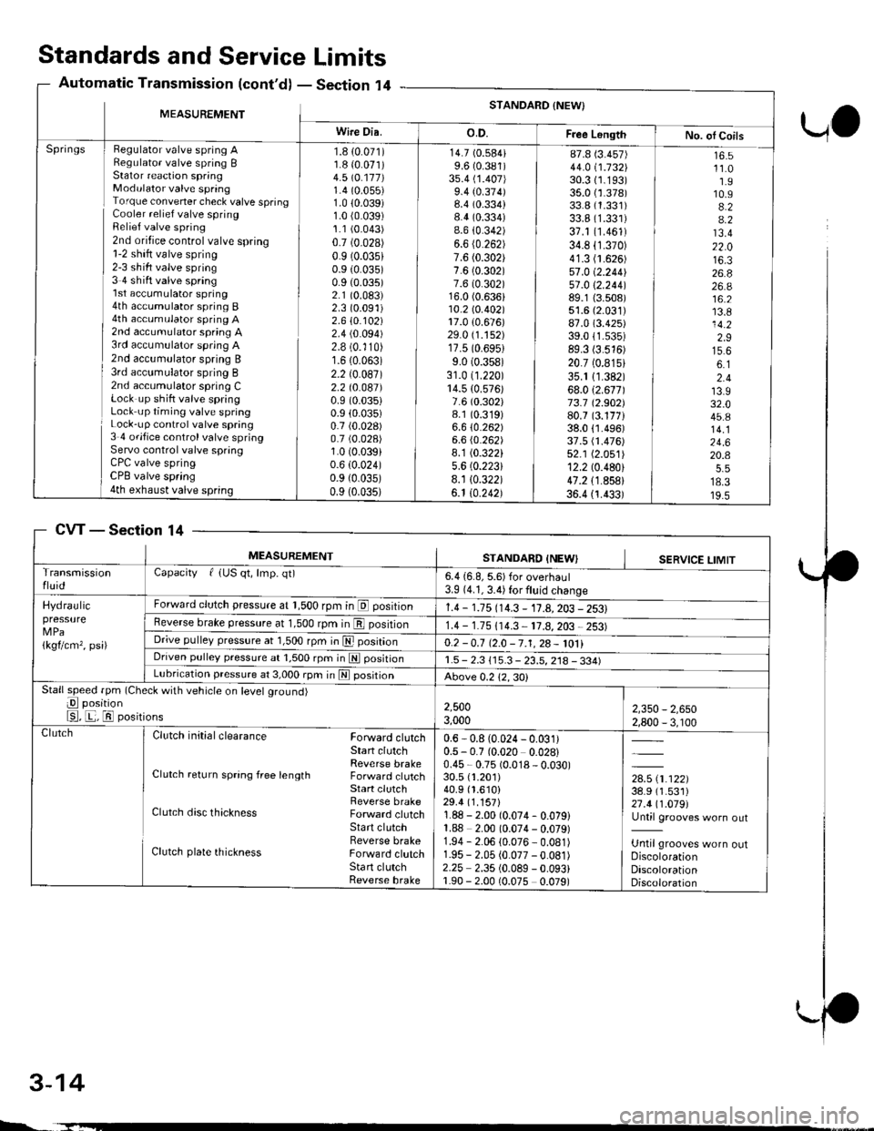
Standards and ServiceLimits
Section '14Automatic Transmission (cont'd)
UO
MEASUREMENTSTANDARD {NEW}
Wire Dia.o.D.Free LongthNo. ol CoilsHegulator valve spring ARegulato. valve spring BStator reaction springModulator valve springTorque convener check valve springCooler relief valve springRelief valve spring2nd oritice control valve spring1-2 shift valve spring2-3 sh ift valve spring3 4 shift valve spring'l st accumulator spring4th accumulator spring B4th accumulator spring A2nd accumulator spring A3rd accumulator spring A2nd accumulator spring B3rd acc!mulator spring B2nd accumulator spring CLock up shift valve springLock up timing valve springLock-up control valve spring3 4 ofifice control valve springServo control valve springCPC valve springCPB valve spring4th exhaust valve spring
Springs1.8 {0.071)1.8 {0.071)4.5 \O.117)1.4 (0.055)
1.0 10.039)1.0 (0.039)
1.1 (0.043)
0.7 (0.028)
0.9 (0.035)
0.9 (0.035)
0.9 (0.035)
2.1 (0.083)
2.3 (0.091)
2.610.102)2.4 (0.094)
2.8 (0.'110)
1.6 (0.063)
2.2 (0.087)
2.2 t0.041)0.9 (0.035)
0.9 (0.035)
0.7 (0.028)
0.7 (0.028)
1.0 (0.039)
0.6 (0.024)
0.9 {0.035)0.9 (0.035)
14.7 (0.584)
9.6 (0.381)
3s.4 (1.407)
9.4 (0.374)8.4 (0.334)
8.4 (0.334)
8.6 {0.342)6.6 (0.262)
7.6 (0.302)
7.6 (0.302)
7.6 (0.302)16.0 (0.636)10.2lo.402l17.0 {0.676)29.0 (1.152)
17.5 (0.6951
9.0 (0.358)
31.0 (1.220)
14.5 {0.576)7.6 (0.302)
8.1 (0.319)
6.610.262)6.6 (0.262)
8.1 (0.322)
5.6 (0.2231
8.1 10.322)6.1 10.242)
87.8 (3.457)
44.0 i.732l'30.3 (1.193)
35.0 {1.378)33.8 (1.331)
33.8 (1.331)
37.1 (1.461)
34.8 (1.370)
41.3 (1.626)
57.0 (2.2441
51 .0 \2.244189.1 {3.508)51.6 (2.031)
87.0 (3.425)
39.011.535)89.3 (3.516)
20.7 (0.815)
35.1 11.382)68.012.671173.7 12.902)80.7 (3.177)38.0 {1.496)37.5 fi.476)52.1 (2.051)
12.2 (0.480)
47.2 {1.858}36.4 {1.433)
16.511.01.910.94.24.213.422.016.326.826.a16.213.814.22.915.66.12.413.932.045.814.124.620.4
18.319.5
CVTSection 14
3-14
MEASUREMENTSTANDARD INEWISERVICE LIMITTransmissionfluidCapacity f {US qt, lmp. qt)6.4 {6.8, 5.6) for overhaul3.9 (4.1, 3.4) for fluid change
Hydraulicpressure
1kgflcm,, psi)
Forward clutch pressure at 1,500 rpm in E position1.4 - 1.15 114.3 - 11.A,203 - 2531Reverse brake pressure at 1,500 rpm in E position1.4 - 1.75 (14.3 11.8,203 2531Dr;ve pulley pressure at 1,500 rpm in E posrtrono.2 -0.7 12.0 -7.1,28- 1011Driven pulley pressure at 1,500 rpm in N positionr.5 - 2.3 115.3 - 23.5, 218 - 334)Lubrication pressure at 3,000 rpm in E posrtronAbove 0.212,30)Stall speed fpm (Check with vehicle on level ground)
E position
E, E, El positions2,5003,0002,350 - 2,6502,800 - 3, r00ClutchClutch initial clearance Forward clutchStart clutchReverse brakeClutch return spring free length Forward clutchStart clutchReverse brakeClutch disc thickness Forward clutchStart clutchReverse brakeClutch plate thickness Forward clutchSta rt clutchReverse brake
0.6 - 0.8 (0.024 - 0.031)0.5 - 0.7 (0.020 0.028)0.45 - 0.75 (0.018 - 0.030)30.5 {1.201)40.9 (1.610)
29.4 (1.157)
1.88 - 2.00 (0.074- 0.079)1.88 2.00 (0.074 - 0.079)1.94 - 2.06 (0.076 - 0.081)1.95 - 2.05 (0.077 -0.081)
2.25 2.35 (0.089 - 0.093)1.90 - 2.00 (0.075 0.079)
,*x.ar}38.9 (1.531)
27.411.019l'Until grooves worn out
Until grooves worn outDiscolorationDiscolorationDiscoloration
L.
Page 62 of 2189
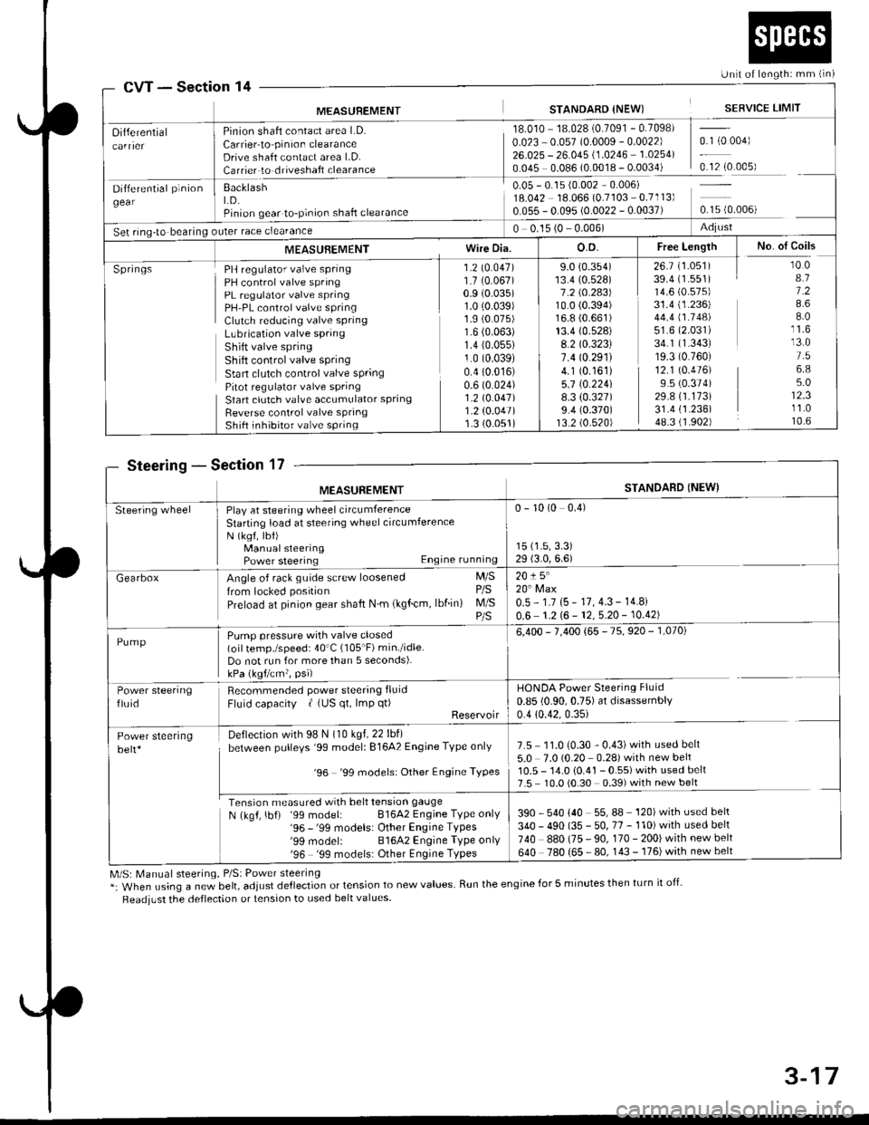
Unit of length: mm lin)
STANDARD {NEW) SERVICE LIMITMEASUREMENT
Differential
Dtri"*"t"|p'.b"gear
S"t rrg-t" b""il"s
Pinion shaft contact area LD.
Carrier-to pinion clearanceDrive shaft contact area l.D.Carrier to driveshaft clearance
BacklashLD.Pinion gear to-pinion shafl clearance
)uter race clearance
18.010 18.028'0.7091 - 0.7098)
0.023 0.057 (0.0009 - 0.0022) 0.1 (0 004)
26.025 - 26.045 (.0246 1 0254\0.045 0.086 (0.0018 - 0.0034) 0.12(0.005)
0 05 - 0.15 i0 002 0.006)18 042 18.066 {0.7103 0.7" l3)
0.055 - 0.095 (0.0022 - 0.0037) 0.15 {0.006)
0 0.15 (0 - 0.006) Adjlrst
MEASUBEMENT Wire DiaO.D. Free Length I No. of Coils
SpringsPH regulator valve spring 1 2 (0 047)
PH control valve spring 1 7 {0.067)PL regulator valve spring 0 9 (0.035)
PH'PL control valve spring 1 0 (0 039)
crutlh reduc'ns vdrve spnns ] :19 9]:lLLbrication valve spring I b (u ubJr
Shitt valve spring 1 4 (0.055)
Shift control valve spring 1 0 (0.039)
Stan clutch control valve spring 0.4 (0 016)
Pitot regulator valve spring 0.6 (0 024)
Start clutch valve accumulator spring 1 2 \0 O47)
Reverse control valve spring 1 2 (0.047)
Shift inhibitor valve spring 1 3 (0 051)
9.0 {0.354)13.4 (0.528)
1.2lO.2A3\10.0 (0.394)
16.8 (0.661)
13.4 (0.528)
8.2 (0.323)
1 .4 t0.29114.1 (0.161)
5.7 t0.224)8.3 {0.327)9.4 (0.370)
13.2 (0.520)
26.7 (1.051)
39.4 (1.551)
14.6 (0.575)
31.4 (1.236)
44.4 \1.14al51.6 (2.031)
34.1 (1.343)
19.3 (0.760)
12.1 (0.476)
9.5 (0.374)
29.8 (1.173)
31.4 (1.236)
48.3 (1.902)
r0.08.11.28.68.0
13.01.56.85.012.311.010.6
Section 14
SteeringSection 17
M/S: [,4anual steering, P/Sl Power steering*: When using a ne; bett, adjust dellection or tension to new values. Run the engine for 5 minutes then turn it off-
Readjust the deflection or tension to used belt values.
cw
MEASUREMENTSTANDARD {NEWI
Steering wheelPlay at steering wheel circumferenceStarting load at steering wheelcircumferenceN (ksf, lbf)Manual steeringPower steering Engine running
0 - 10 (0 0.4)
15 (1.5,3.3)
29 (3.0,6.6)
GearboxAngle of rack guide screw loosened M/S
from locked position P/S
Preload at pinion gear shaft N m (kglcm, lbfin) M/S
20!5"20'Max0.5 - 1.7 (5 - 17,4.3 - 14.8i
0.6 1.2 (6 - 12, 5.20 - 10.42)
Pump pressure with valve closed(oil temp./speed: 40'C (105"F) min./idleDo not run for more than 5 seconds).kPa (kgtcm?, psi)
6,400 - 7,400 {65 - 75, 920 - 1,070)
Power steeringfluidRecommended power steering fluid
Fluid capacity | {US qt, lmp q0Reservoir
HONDA Power Steering Fluid
0.85 (0.90,0.75) at disassembly0.4 {0.42.0.35}
7.5 11.0 {0.30 - 0.43)with used belt
5.0 7.0 (0.20 0.28) with new belt10.5 - 14.0 10.41 - 0.55) with used belt7.5 10.010.30 0.39) with new belt
390 540 {40 55,88 '120) wrth used bek
340 - 490 (35 - 50, 77 - 110) with used belt
740 880 (75 - 90, 170 - 200) with new belt
640 780 (65 - 80, 143-176)with newbelt
Power steeringbelt*
Deflection with 98 N (10 kgf,22 lbf)
between pulleys '99 modell 81642 Engine Type only
'96 '99 models: Other Engine TYPes
ron.ionffiN (kgf, lbf) '99 model: 81642 Engine Tvpe only'96 -'99 models: Other Engine TYPes'99 modelr 81642 Engine TYPe onlY'96 '99 models: Other Engine TYPes
3-17
Page 64 of 2189
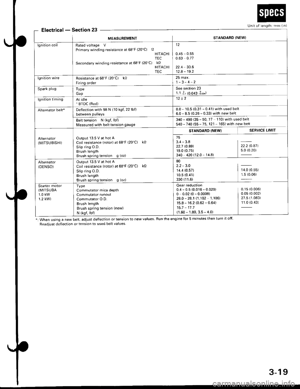
ElectricalSection 23
*: When using a new belt, adjust deflection or tension to new values. Run the engine for 5 minutes then turn it off
Readiust deflection or tension to used belt values
Unit of englh: mm {n)
MEASUREMENTSTANDARD {NEW}
lgnition coilRated voltage VPrimary winding resistance at 68'F (20'C) oHITACHITEC
Secondary winding resastance at 68'F 120"C) kOHITACHITEC
12
0.45 0.550.63 0.11
22.4 - 33.612.A - 19.2
lgnition wireResistance at 68'F (20'C) kf)
Firing order
25 max.1-3-4 2
Spark plugTypeGap
See section 231.1 3, (o.o€ -3*.)
lgnition timingAt idle' BTDC lRed)
Alternator belt+Deflection with 98 N (10 kgf,22lbf)between pulleys8.0 - 10.5 {0.31 - 0.41} with used belt
6.0 - 8.5 {0.26- 0.33)with new belt
Belt tension N (kgf, lbf)
Measured with belt tension gauge340 - 490 (35 - 50, 77 110) with used belt
540 - 740 (55 - 75, 121. 165)whh newbert
(MITSUBISHI)Output l3.5 V at hot ACoal resistance (rotor) at 68'F (20"C) kO
Slip rins O.D.Brush lengthBrush spring tension g (oz)
STANDARD INEWI SERVICE LIMIT
753.4-3.8 I -
Z2.j \0.A9) 22.2 \0.47)19.0 (0.75) 5.0 (0.20)
340 420 (12.0 14.8)
Alternator(DENSOiOutput '13.5 V at hot A
Coil resistance (rotor) at 68'F (20'C) k0
Slip ring O.D.Erush lengthBrush spring tension g (oz)
802.2 - 3.014.4 (0.57) | 14.0 (0.55)
10.5 (0.41) 1.5 (0.06)
330 {11.6)
Starter(MITSUEA
1.0 kw1.2 kW)
TvpeCommutator mica depthCommutator runoutCommutator O.D.Brush lengthBrush spring tension (new)
N (ksf, lbf)
Gear reduction0.4 - 0.5 (0.016 - 0.020) 0.15(0.006)
o o.o2 (o - 0.000e) | o.o5 (o.oo2)
28.0-28.1 (1.102 1.106) | 27.5(1.083)
15.8 - 16.2 10.62 - 0.64) 11.0 (0.43)
15.7 - 11 .1
{1.60 - 1.80, 3.5 - 4.0i
3-19
Page 96 of 2189
Engine RemovaUlnstallation
Removal
@@
1.
. Make sure iacks and salety stands are placed ploperly
and hoist brackets are attached to the correct posi-
tions on the engine.
. Make sure the vehicle will not roll off stands and fall
while you are working under it.
CAUTION:
. Use fender covers to avoid damaging painted sur-face.
. Unplug the wilin9 connectors caretully while holdingthe conngstor portion to avoid damage,. Mark all wiring and hosos to avoid misconnoction.
Also, be sure that they do not contact other wiring or
hoses or interfere with other parts,
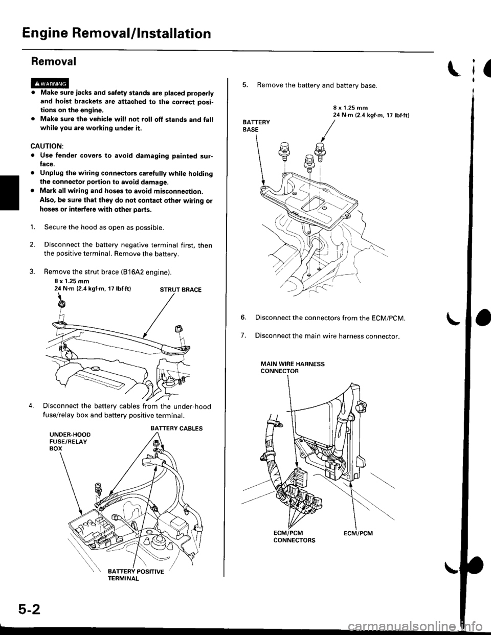
Secure the hood as open as possible.
Disconnect the battery negative terminal first. thenthe positive terminal. Remove the battery.
Remove the strut brace (B'16A2 engine).
8 x 1 .25 mm24 N.m {2.4 kgl.m, 17 lbf.ft}
Disconnect the battery cables from the under-hood
fuse/relay box and battery positive terminal.
STRUT BRACE
UNDER.HOODFUSE/RELAYBOX
BATTERY CABLES
5-2
ECM/PCM
(
5. Remove the battery and battery base.
8 x 1.25 mm24 N.m (2.4 kgf.m, 17 lbf ftl
7.
Disconnect the connectors from the ECM/pCM.
Disconnect the main wire harness connector.
MAIN WIRE HARNESSCONNECTOR
Page 97 of 2189
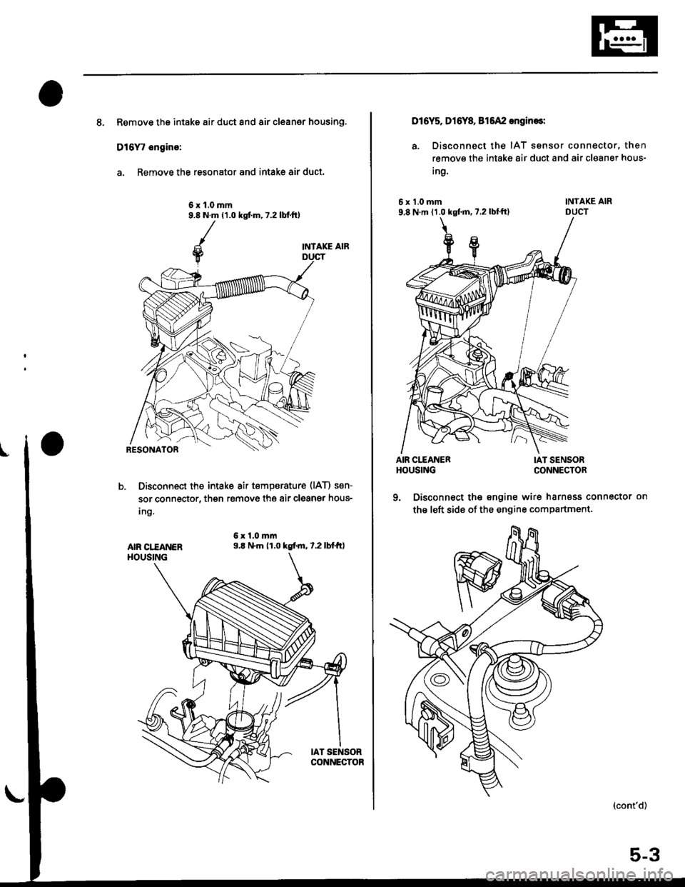
8. Remove the intake air duct and air cleaner housing.
D16Y, ongino:
a. Remove the resonator and intake air duct.
6x1.0mm9.8 N.m (1.0 kgt m, 7.2 lbf.tt)
INTAKE AIR
Disconnect the intake air tempsrature (lAT) sen-
sor connector, then r€move thg air cleaner hous-
Ing.
6x1.0mm9.E N.m (1.0 kgtm, t.2lbtft,AIR CI."EANERHOUSING
IAT SENSORCONNECTOR
016Y5, Dl6Y& 815A2 engin€sl
a. Disconnect the IAT sensor connector, then
remove the intake 8ir duct and air cleaner hous-
Ing.
6x1.0mm9.8 N m {1.0 kgtm, 7.2 lbl'ft)
AIR CITANERHOUSING
INTAKE AIRDUCT
IAT SENSORCONNECTOR
9. Disconnect the engine wire harness connector on
the left side of the engine compartment.
(cont'd)
5-3
Page 99 of 2189
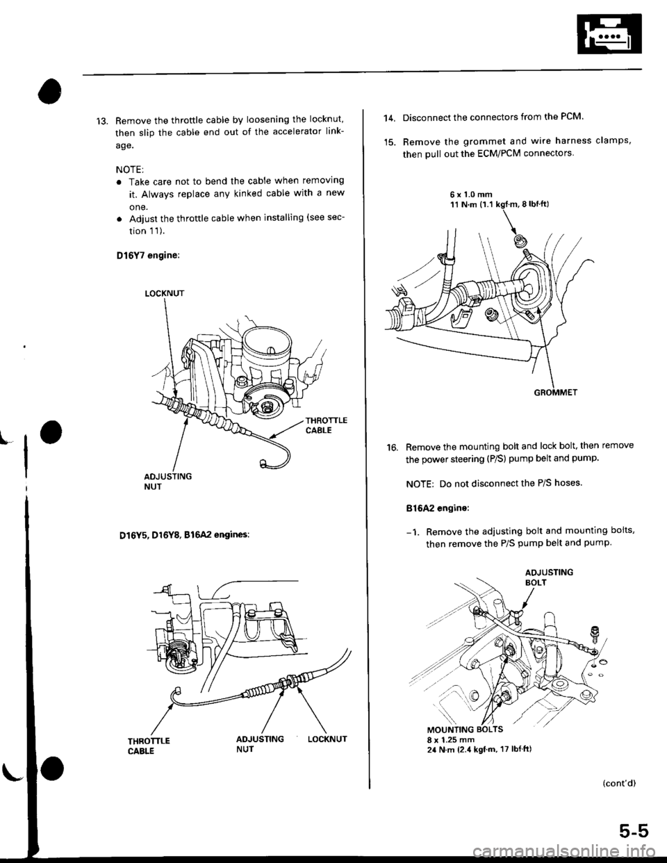
13. Remove the throftle cable by loosening the locknut,
then slip the cable end out of the accelerator link-
age.
NOTE;
. Take care not to bend the cable when removing
it. Always replace any kinked cable with a new
one.
. Adjust the throttle cable when installing (see sec-
tion 1 1).
D16Y7 engine:
D16Y5, D16Y8, B16A2 engines:
LOCKNUT
LOCKNUT
14,Disconnect the connectors from the PCM.
Remove the grommet and wire harness clamps,
then pull out the ECM/PCM connectors
6x1.0mm
16. Remove the mounting bolt and lock bolt, then remove
the power steering (P/S) pump belt and pump
NOTE: Do not disconnect the P/S hoses.
816A2 engine:
Remove the adjusting bolt and mounting boits,
then remove the P/S pump belt and pump
(cont'd)
5-5
AOJUSTING
Page 101 of 2189
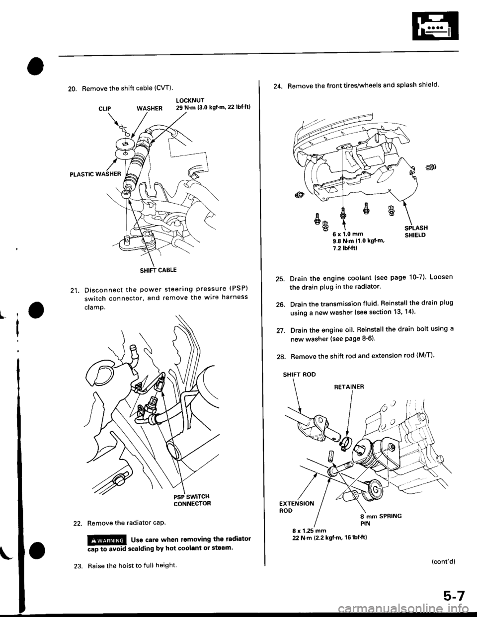
20. Remove the shift cable (CVT)
WASHER
Pt-Aslc
21. Disconnect the Power
switch connector, and
cramp.
LOCKNUT29 N.m {3.0 kgf m,22lbf'ft}
steering pressure (PSP)
remove the wire harness
CLIP
ll
I
Remove the radiator caP.
!!!@ usa care when l€moving the tadiator
Ap to avoid scalding by hot coolant or steam'
Raise the hoist to full height.
SHIFT CABLE
(cont'd)
25.
26.
27.
24. Remove the front tires/wheels and splash shield.
u x l.u mm SHIELD9.8Nm(1 0 kqt'm,
7.2lbf.ftl
Drain the engine coolant (see page 10-7). Loosen
the drain plug in the radiator.
Drain the transmission fluid Reinstall thedrainplug
using a new washer (see section 13, 14).
Drain the engine oil. Reinstall the drain bolt using a
new washer (see page 8-6).
28. Remove the shift rod and extension rod (M/T)
SHIFT ROD
EXTENSIONROD
8 x 1.25 mm22 N.m t2.2 kgf'm, 't6lbtft)
ER
6x1.0mm
Page 105 of 2189
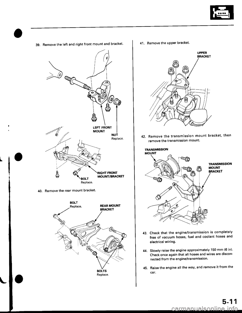
39. Remove the left and right front mount and bracket'
MOUNT/BRACKET
40. Remove the rear mount bracket.
41. Remove the uPPsr bracket.
42. Remove the transmission mount bracket, then
remove the transmission mount.
44.
Check that the engine/transmission is completely
free of vacuum hoses, fuel and coolant hoses and
electricalwiring.
Slowly raise the engine approximately 150 mm (6 in)'
Check once again that all hoses and wires are discon-
nected from the engine^ransmission
Raise the engine all the way, and remove it from the
car.
UPPER
TRANSMISSION
45.
5-11
Page 114 of 2189
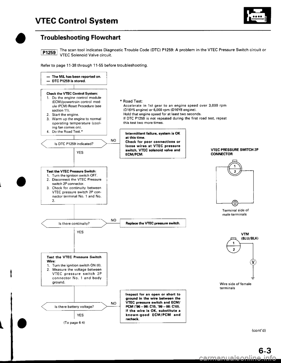
VTEC Control System
Troubleshooting Flowchart
tFtrsrl #ilH:::lj1t:"J:T,?ffnostic
rrouble code (Drc) Pr25e: A probrem in the vrEc Pressure switch circuit or
Reter to page 1 l-38 th roug h 1 1-55 before trou bleshooting.
* Road Test:Accelerate in 1st gear to an engine speed over 3,000 rpm(D16Y5 engine) or 6,000 rpm (D'16Y8 engine).Hold that engine speed for at least two seconds.It DTC P1259 is not repeated during the first road test, repeatthis test two more tames.
VTEC PRESSURE SWITCH 2PCONNECTOR
Terminal side ofmale terminals
Wire sid6 ol femalerermtnats
VTM
l1 (BLu/BLK)
f;-) |I
I
Y
I
The MIL has been reoorted on.DTC P1259 is sto.ed.
Check the VTEC Cont.ol Syst6m:1. Do the engine control module(ECM)/powertrain control module lPCM) Reset Procedure (see
section 11).2. Stan the engine.3. Warm up the engine to normaloperating temperature (cool-
ing fan comes on).4. Do the Boad Test.*Intermittont tailura, 3y3t.m is OKat thia time.Check for ooor connoctionr o.loose wirea at VTEC oiassurclwitch, VTEC solonoid valvo .ndECM/PCM,
ls OTC P1259 indicated?
Test rhe VTEC Prensure Switch:1. Turn the ignition switch OFF.2. Disconnect the VTEC Pressureswitch 2P connector.3. Check for continuity betweenVTEC pressure switch 2P con-nector terminal No. 1 and No.2.
Replace the VTEC preasure 3witch.ls there continuity?
Te3t the VTEC Pressure SwitchWire:1. Turn the ignition switch ON lll).2. Measure the voltage betweenVTEC press u re switch 2Pconnector No. l and bodyground.
In3poct for en opon or shod toground in thG wi.. bctwoon thoVTEC pro$ur6 switch rnd ECM/PCM l'96 - 9a: C15,'99 - 00: C101.lf tha wiro i3 OK,3ubrtitute aknown-good ECM/PCM andrecheck.
ls there battery voltage?
{To page 6'4i
Page 115 of 2189
I
VTEC Control System
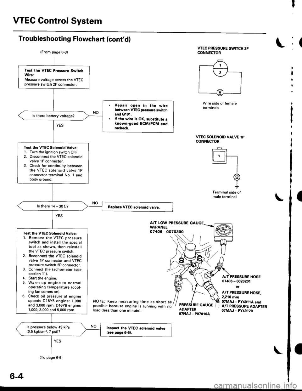
Troubleshooting Flowchart (cont'd)
VTEC PRESSURE SwlTCH 2PCONNECTOR
Wire side of female(€rmrnats
VTEC SOLENOID VALVE lPCONNECTOR
I r----'t I
ll ' ff---r'�-'�1
I
I
-L
Terminal side ofmale terminal
A/T LOW PRESSUREw/PAt{EL07406-0070300
NOTE: Keep measuring time as short aspossible because engine is running with noload (less than one minute).
PRESSURE GAUGEADAPTER07NAJ - P07010A
A/T PRESSURE I{OSE07406 - 0020201
ot
A/T PRESSURE HOSE.2,210 mm07MAJ - PY&llA andA/T PRESSURE ADAPTER07MAJ - PY,()120
6-4
(From page 6-3)
(To page 6-5)
Test the VTEC Pr6suro SwitchWiro:Nleasure voltage across the VTECpressure switch 2P connector.
. Rcpai. opon in tho wirebrtw.en VTEC pr6.urc switchand G101.. lf th. wir6 b OK, sub.thuto alnown-good ECM/PCM !ndracheck.
ls there baftery voltage?
Te3t the VTEC Solonoid V.lve:1. Turn the ignition switch OFF.2. Disconnect the VTEC solenoidvalve 1P connector.3. Check for continuity betweenthe VTEC solenoid valve 1Pconnector terminal No. 1 andbody ground.
ls there 14 - 30 0?
Te3t tho WEC Solonoid Vatvo:'1. Remove the VTEC pressureswatch and install the specialtool as shown, then reinstallthe VTEC pressure switch.2. Reconnoct the VTEC solenoidvalve 1P connector and VTECpressure switch 2P connector.3, Connect the tachometer (seesection 11).4. Stan the engine.5, Warm up engine to normaloperating temperature (cool,ing fan comes on).6. Check oil pressure at enginespeeds D16Y5 engine: 1,000and 3.000 rpm, D16Y8 engine:1,000,3,000 and 5,000 rpm.
ls pressure below 49 kPa(0.5 kgflcm,, 7 psi)?In.poct the VTEC aolonoid vllvols.c p.g. &6).
:(
t
I
t
:
t
I
I