light HONDA CIVIC 2000 6.G Owners Manual
[x] Cancel search | Manufacturer: HONDA, Model Year: 2000, Model line: CIVIC, Model: HONDA CIVIC 2000 6.GPages: 2189, PDF Size: 69.39 MB
Page 778 of 2189
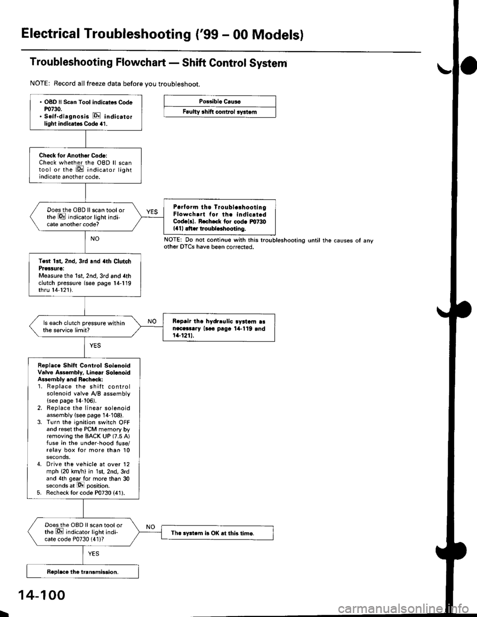
Electrical Troubleshooting ('99 - 00 Modelsl
Troubleshooting Flowchart - Shift Control System
NOTE: Record allfreeze data before you troubleshoot.
Po33ibl. Crus6
Frulty 3hift control ryrtom
. OBD ll Scan Tool indicrtd Codem730.. Self-dirgnosis E indicatorlight indicst€. Codo 41.
Check for Anoth€. Code:Check whether the OBD ll scantool or the E indicator lightindicate another code.
Prrf orm tho Troublc!hootingFlowch.rt for th. indicrt.dCod.l3l. R.ch.ck tor cod. m730141| .tt r troubldhootlng.
Doesthe OBD llscan tool orthe E indicator light indi-cate another code?
Test 13t, 2nd, 3rd .nd 4th ClutchPrglture:Measure the 1st, 2nd,3rd and 4thclutch pressure (see page 14-119thru 14 121).
R.prir tho hydrlulic ayrtam aan.c.3t..y lr.o p!9. lil-119 rnd1+1211.
ls each clutch pressure withinthe service limit?
Roplace Shift Control SolenoidValve Asembly. Linoar Sol.noidAssembly .nd Recheck:1. Replace the shift controlsolenoid valve A/B assembly(see page 14-106).2. Replace the linear solenoidassembly {see page 14-108}.3. Turn the ignition switch OFFand reset the PCM memory byremoving the BACK UP (7.5 A)fuse in the under-hood fuse/relay box for more than 10seconds,4. Drive the vehicle at over 12mph (20 kn/h) in 1st, 2nd, 3rdand 4th gear lo. more than 30seconds at lPll position.5. Recheck for code P0730 (41).
Doesthe OBD Ilscan tool orthe E ;ndicator light indi-cate code P0730 (41)?Th. sFtcm b OK .t this time.
NOTE: Do not continue with this lroubleshooting until the causes ot anyother OTCS have beon corrected.
I
14-100
Page 779 of 2189

Troubleshooting Flowchart - El Indicator Light On Constantly
PCM CONNECTOR A I32P)
Wire side of lemale terrnanals
PCM CONNECTOR D {16P)
ATP D'
25
61e 11(12
t{Iro
(YELI
Wire side of female terminals
The Dll indicator lighi is on con-stantly {not blinking) whenever
the ignition switch is ON (lll.
Moasure D4 IND Voltage:1. Turn the ignition switch OFF.2. Disconnect the A {32P} con-nector from the PCM.3. Turn the ignition switch ON (ll).
4. Measure the voltage betweenthe A14 terminal and bodyground.
Repsir short to power in the wire
between the A14 torminal andthe gauge assembly.
Measure ATP D4 Voltagel1. Turn the ignition switch OFF.2. Connect the A (32P) connector to the PCM.3. Turn the ignition switch ON (ll).
4. Shitt to any position othertha n [ql.5. Measure the voltage betweenthe D9 terminal and bodyground.
ls there approx. 5 V?
Test the A/T gear position switch(see section 23).
Check Ior a short to ground inthe wire betweon the D9 termi-
nal and A/T gear position switch.It wire is OK, substitute a known-good PCM and recheck.
Page 780 of 2189
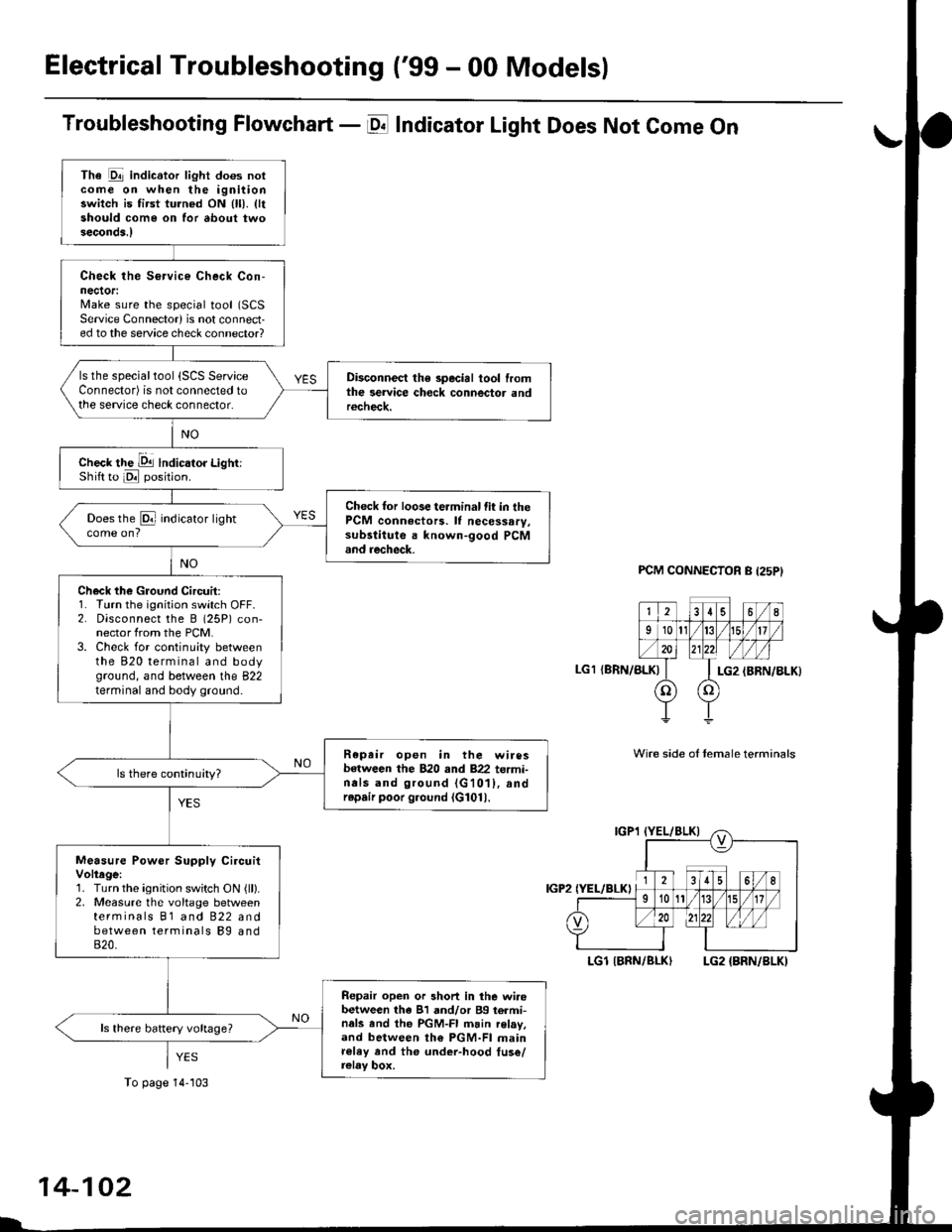
Electrical Troubleshooting ('99 - 00 Models)
Troubleshooting Flowchart - E Indicator Light Does Not Come On
FCM CONNECTOR B (25P}
LGl {8RN/ALKI{BRN/8LK}
Wire side ol temale terminals
LGl IBNN/BLK} LG2 {BRN/BLK)
i2t5 6q
910t7
LG2
o) (o
The Pll indicator light does notcome on when the ignitionswitch is fi.st turned ON (ll). lltshould come on for about twoseconda.l
Check the Service Check Con-nector:Make sure the special tool (SCS
Service Connector) is not connect-ed to the service check connector?
ls the specialtool {SCS ServiceConnector) is not connected tothe seNice check connector.
Disconnect the special tool fromthe service check connector andr6check.
Check the Dll lndicator LightiShift to d position.
Check for loose terminal fit in thePCM connecto13. It necessary.sub3titute a known-good PCMand recheck.
Does the @ indicator lightcome on?
Check the Ground Circuit:1. Turn the ignition switch OFF.2. Disconnect the B (25P) con-nector from the PCM.3. Check for continuity betweenthe 820 terminal and bodyground, and between the 822terminal and body ground.
Repair open in the wiresbetween the B20 rnd 822 termi-nals and ground (G101), andrep.ir poor ground (G1011.
Measure Power Supply CircuitVoltage:1. Turn the ignition switch ON {ll}.2. Measure the voltage betweenterminals B1 and 822 andbetween terminals Bg and820.
Repair open or short in the wi.obetween th6 81 and/or 89 termi-nals and the PGM-FI main relav,and between th€ PGM-FI mainr€ley rnd the under-hood tus€/relay box.
To page 14''103
14-102
Page 781 of 2189
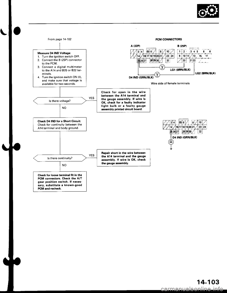
From page 14-102
Measu.e D4 IND Voltago:1. Turn the ignition switch OFF.2. Connect the B (2SPiconnector
to the PCM.3. Connect a digital multimeter
to the A14 and 820 or 822 ter-
4. Turn the ignition switch ON (ll),
and make sure that voltage isavailable for two seconds.
Chock for ooon in tho witebetween the A't4 tsrminal .ndthe gauge.3s.mbly. ll wite i3OK, chock to. a t.ulty indicatorlight bulb or. feulty gaugc
e336mbly p.inted circuit board.
Check D4 IND lor a Short Citcuit:Check lor continuity between theA14 terminal and body ground.
Rop.ir short in thc wirg b€twoenth. Al4 tormin.l .nd tho gaugo
a$ombly. ll wiro is OK. chocktho gsugo a3rambly.
ls there continuity?
Check fo. loose terminal tit in thcPCM connectoB. Chock the A/Tgear position switch. It ncce3-sary, substitute a known-goodPCM and rechock.
PCM CONNECTORS
Wire side ol female terminals
14-103
Page 782 of 2189
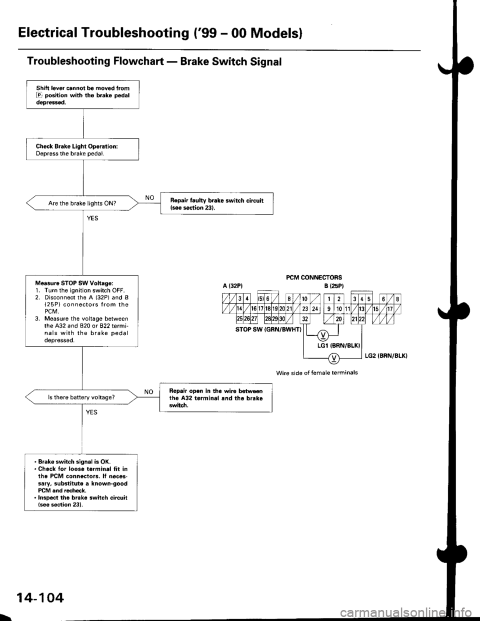
ElectricalTroubleshooting ('99 - 00 Modelsl
Troubleshooting Flowchart - Brake Switch Signal
PCM CONNECTORS
Wire side of female terminals
Shift lever cannot be moved tromE position with tho b.ake pedaldepressod.
Check Brake Light Operation:Depress the brake pedal.
Repair t ulty brake switch circuit{see s€ction 23}.Are the brake llghts ON?
Mea3ure STOP SW Vohage:1. Turn the ignition switch OFF.2. Disconnect the A (32P) and B{25P} connectors from thePCM,3. Measure the voltage betweenthe A32 and 820 or 822 termi-nals with the brake pedal
depressed.
Repair open in the wire betwsenthe A32 terminal rnd tho brrk6switch.
ls there battery voltage?
. Brak€ switch sign.l is OK.. Check for loose terminal fil inlhe PCM conn€ctors. lf neces-sary. substitute a known-goodPICM and recheck.. InsDect the breke 3witch circuitlsee section 231.
B {25P)
\
14-104
Page 803 of 2189
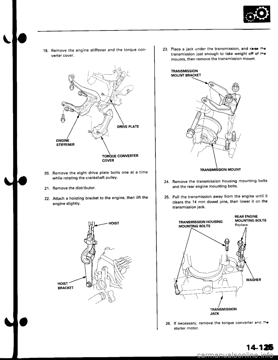
19. Remove the engine stiffener and the torque con-
verter cover.
Remove the eight drive plate bolts one at a tlme
while rotating the crankshaft pulley.
Remove the distributor.
Attach a hoisting bracket to the engine, then lift the
engine slightly.
HOISTBRACKET
20.
21.
COVER
23. Place a jack under the transmission. and ra6a :'.
transmission iust enough to take weight otf ol tF.
mounts. then remove the transmission mounl
TRANSMISSIONMOUNT BRACKET
Remove the transmission housing mounting bolts
and the rear engine mounting bolts.
Pull the transmission away from the engine until it
clears the 14 mm dowel pins, then lower it on the
transmission jack.
TRANSMISSION HOUSING
lf necessary, remove the torque converter anc:"
starter motor.
24.
25.
1+16
Page 817 of 2189
Valve Body
2.
Repair
NOTE: This repair is only necessary if one or more of
the valves in a valve body do not slide smoothly in their
bores. You may use this procedure to free the valves in
the valve bodies.
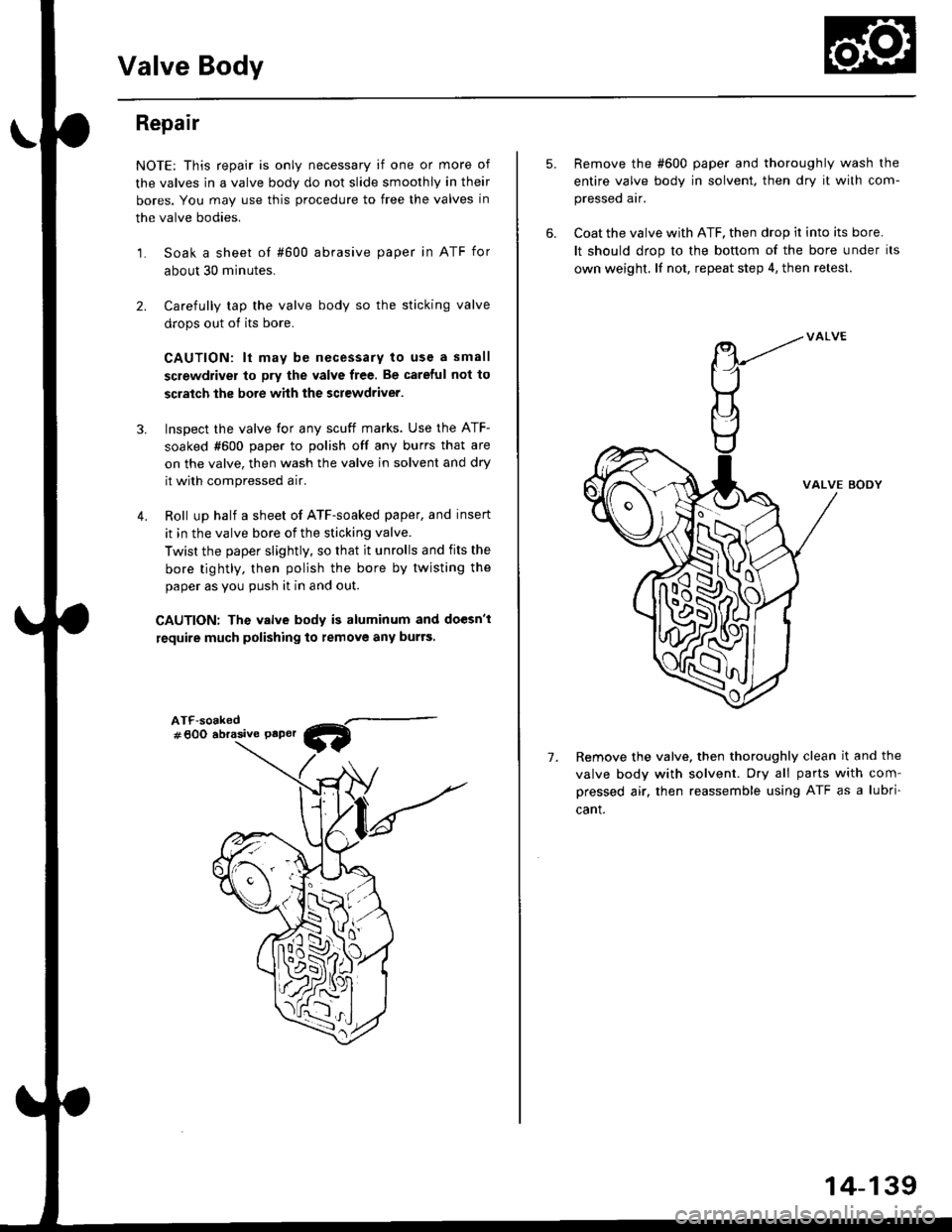
1. Soak a sheet of #600 abrasive paper in ATF for
about 30 minutes.
Carefully tap the valve body so the sticking valve
drops out of its bore.
CAUTION: lt may b€ necessary to use a small
screwdriver to pry the valve free. Be careful not to
scratch the bore whh the screwdriver.
Inspect the valve for any scuff marks. Use the ATF-
soaked #600 paper to polish off any burrs that are
on the valve, then wash the valve in solvent and dry
it with compressed a ir.
Roll up half a sheet of ATF-soaked paper, and insert
it in the valve bore of the sticking valve.
Twist the paper slightly, so that it unrolls and fits the
bore tightly, then polish the bore by twisting the
paper as you push it in and out.
CAUTION: The valve body is aluminum and doesn't
require much polishing to remove any burrs,
3.
4.
ATF-soaked#600 abrasive Paper
5.
7.
Remove the #600 paper and thoroughly wash the
entire valve body in solvent. then dry it with com-
pressed air.
Coat the valve with ATF, then drop ir into its bore.
It should drop to the bonom of the bore under its
own weight. lf not, repeat step 4, then retest.
VALVE BODY
Remove the valve. then thoroughly clean it and the
valve body with solvent. Dry all parts with com-
pressed air. then reassemble using ATF as a lubri
cant.
W
-M
14-139
Page 882 of 2189
Description
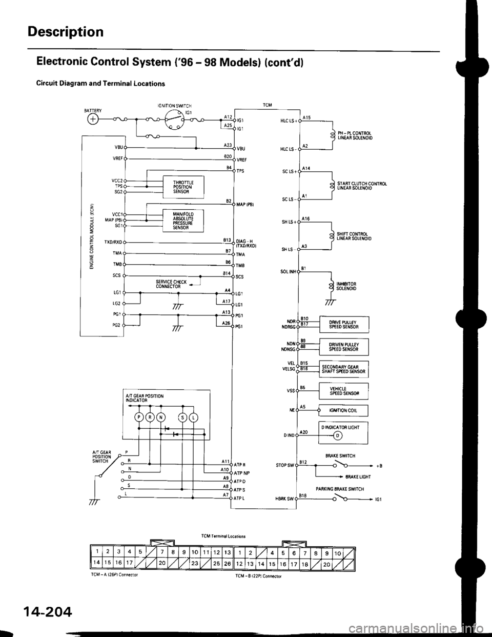
Electronic Control System ('gG - 98 Modelsl (cont'dl
Circuit Diagram and Terminal Locations
GNITIONSWITCN
Pri - Pt coNTnoLLrN ns0LtN0t0
SIAiT CLUTCH CONTSOLLINEAFSOLENOID
sHtFT CONmOILINIAftSOLENOID
BFAXELIGHT
PAS|(ING 8MI(E SWITCH
i\c-...............- +B
i\--------.--_ rcr
: MAP(PBIg s61
E rtDiRxo
g TM8
scs
123518I1011't22578910
14172023261213t4t6171820
D
14-204
Page 900 of 2189
Description
Park Mechanism
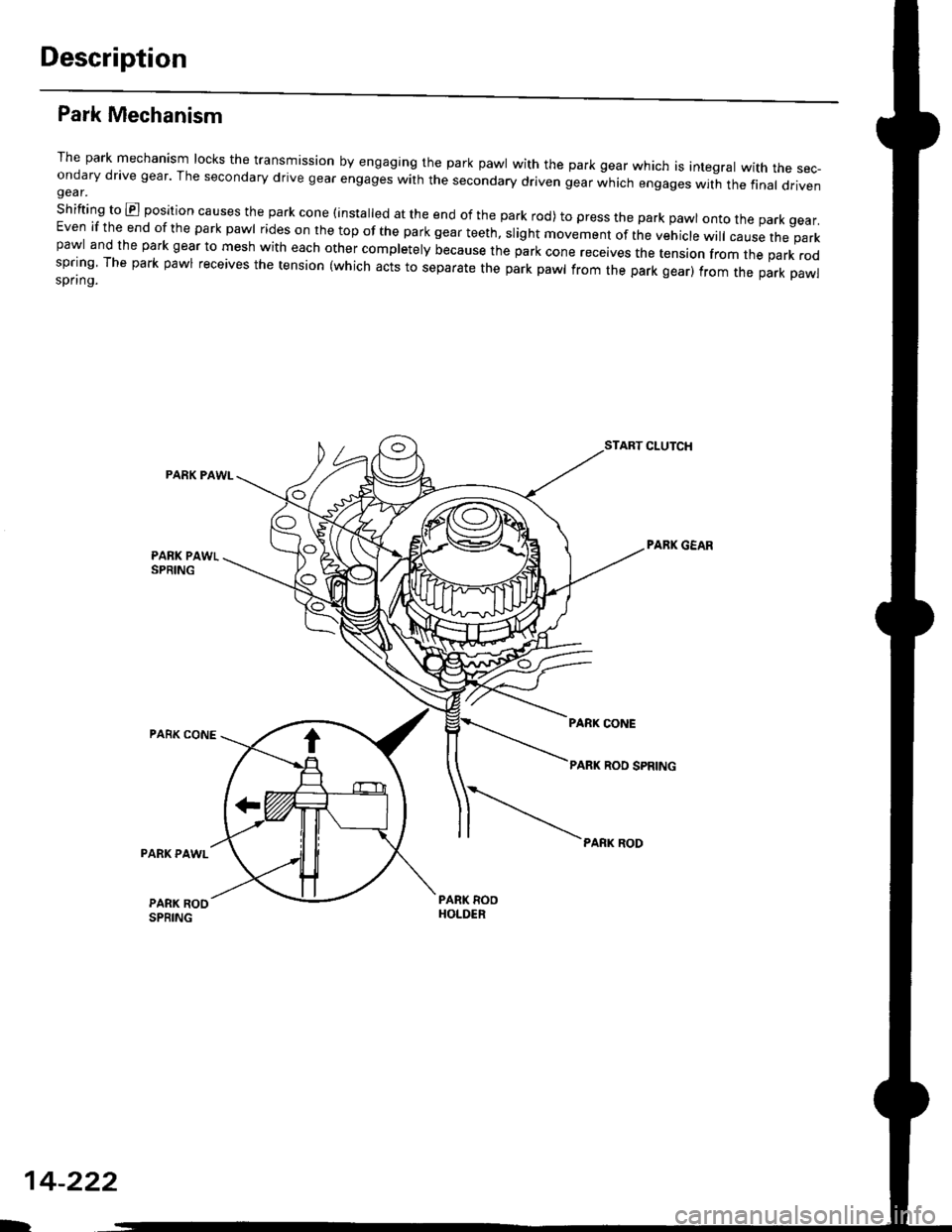
The park mechanism locks the transmission by engaging the park pawl with the park gear which is integral with the sec-ondary drive gear' The secondary drive gear engages with the secondary driven gear which engages wit-h the final drivengear.
shifting to E position causes the park cone (installed at the end of the park rod) to press the park pawl onto the park gear.Even if the end of the park pawl rides on the top of the park gear teeth, slight movement of the vehicle will cause the parkpawl and the park gear to mesh with each other completely because the park cone receives the tension from the park rodspring The park pawl receives the tension (which acts to separate the park pawl from the park gear) from the park pawlspring.
PARK PAWI-
PARK CONE
START CLUTCH
PABK GEAR
PARK RODPARK PAWL
PARK ROOSPRING
14-222
D
Page 905 of 2189
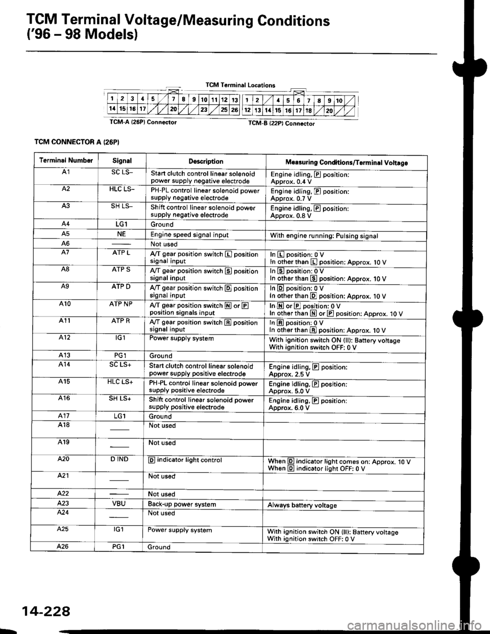
TCM Terminal Voltage/Measuring Gonditions
('96 - 98 Modelsl
TCM Terminal Loc.tions
TCM-A l25P) Connecto.
TCM CONNECTOR A (26P}
TCM-B (22P) Connectot
2418910111213
1115161720232526
Terminal NumbetSignalDsscriptionMoasuring Conditions/Torminsl Vohrgo
A1SC LS_Stan clutch control linear solenoidpower supply negative electrodeEngine idling, E position:Approx. 0.4 VHLC LS-PH-PL control linear solenoid Dowersupply negative electrodeEngine idling, E position:Approx. 0.7 V
Shift control linear solenoid oowersupply negative electrodeEngine idling, E position:Approx. 0.8 V
A4LG1Ground
NEEngine speed signal inputWith engine running: Pulsing signalA6Not used
A7ATP LA/f gear position switch El positionsignal inputInEposition:OVIn other than El position: Approx. 1O VA8ATP Sly'T gear position switch E positionsignal inputIn lg position: 0 VIn other than E position: Approx. 10 VA9ATP DA{/T gear position switch E positionsignal inputIn lll position: 0 VIn other than E position: Approx. 10 VAr0ATP NPA,/T gear position switch E or Eposition signals inputInEorEposition:oVIn otherthan E orE position: Approx. 1O VA11ATP RA,/T gear position switch E positionsignal inputIn lE position: 0 VIn other than E position: Approx. 1O VA.12tGlPower supply systemWith ignition switch ON (ll): Banery voltsgeWith ignition switch OFF: 0 VA13PG1Ground
414Start clutch control linea. solenoidpower supply positive electrodeEngine idling, E position:Approx. 2.5 VA15HLC LS+PH-PL control line8|. solenoid powersupply positive electrodeEngine idling, El position:Approx. 5.0 VA16SH LS+Shift control linear solonoid oowersupply positive electrodeEngine idling, E position:Approx. 6.0 V417Ground
A18Not used
A19Not used
420D INDE indicator light controlWhen l9l indicator light comes on: Approx. jO VWhen lll indicator lighr OFF: 0 VA2'lNot used
422Not used
VBUBack-up power systemAlways battery voltage424Not used
A.25tG1Power supply systemWith ignition switch ON (lt): Baftery voltageWith ignition switch OFF:0 VPG1Ground
L
14-228