width HONDA CIVIC 2000 6.G User Guide
[x] Cancel search | Manufacturer: HONDA, Model Year: 2000, Model line: CIVIC, Model: HONDA CIVIC 2000 6.GPages: 2189, PDF Size: 69.39 MB
Page 152 of 2189
Valve Guides
7.
VALVESEAT
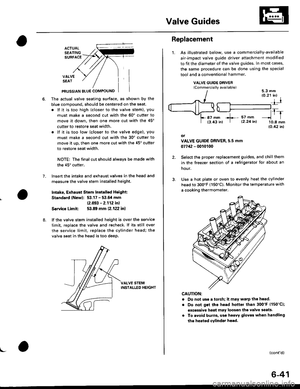
PFUSSIAN BTUE COMPOUNO
The actual valve seating surface. as shown by the
blue comDound, should be centered on the seat.
. lf it is too high (closer to the valve stem), you
must make a second cut with the 60'cutter to
move it down, then one more cut with the 45'
cutter to restore seat width,
. lf it is too low (closer to the vslve edge), you
must make a second cut with the 30" cutter to
move it uD, then one more cut with the 45'cutter
to restore seat width.
NOTE: The final cut should always be made with
the 45" cutter.
lnsert the intake and exhaust valves in the head and
measure the valve stem installed height.
Intake. Exhau3t Siem Installsd Height:
Standard (New): 53.17 - 53.6,4 mm
12.093 - 2.112 in)
Sorvice Limit: 53.89 mm (2.122 in)
lf the valve stem installed height is over the service
limit. reDlace the valve and recheck. lf its still over
the service limit, replace the cylinder head; the
valve seat in the head is too deep.
VALVE STEMINSTALLED HEIGHT
8.
\-
Replacement
1.As illustrated below, use a commercially-available
air-impact valve guide driver attachment modified
to fit the diameter of the valve guides. In most cases.
the same procedure can be done using the special
tool and a conventional hammer.
VALVE GUIDE DRIVERlCommerciallv available)5.3 mm
87 mm +- 57 mft
t3.43 in) | 12 24 inl
tr-r'10.8 mm(0.42 inl
or
VALVE GUIDE DRIVER, 5.5 mm
07742 - 0010100
Select the proper replacement guides. and chill them
in the freezer section of a refrigerator for about an
nour.
Use a hot plate or oven to evenly heat the cylinder
head to 300"F (150'C). Monitor the temperature with
a cooking thermometer.
CAUTION:
. Do not use a torch; it may warp the head.
Do not got the head hottel than 300"F (150"C1;
excessive heat may loosen thg valve seats.
To avoid burns. use heayy gloves whon handling
the heated cylinder h€ad.
{cont'd)
6-41
Page 188 of 2189
Valve Seats
Reconditioning
1. Renew the valve seats in the cylinder
valve seat cutter.
NOTE: lf any guides are worn (see
replace them (see page 6-80) before
valve seats,
head with a
page 6-79),
cutting the
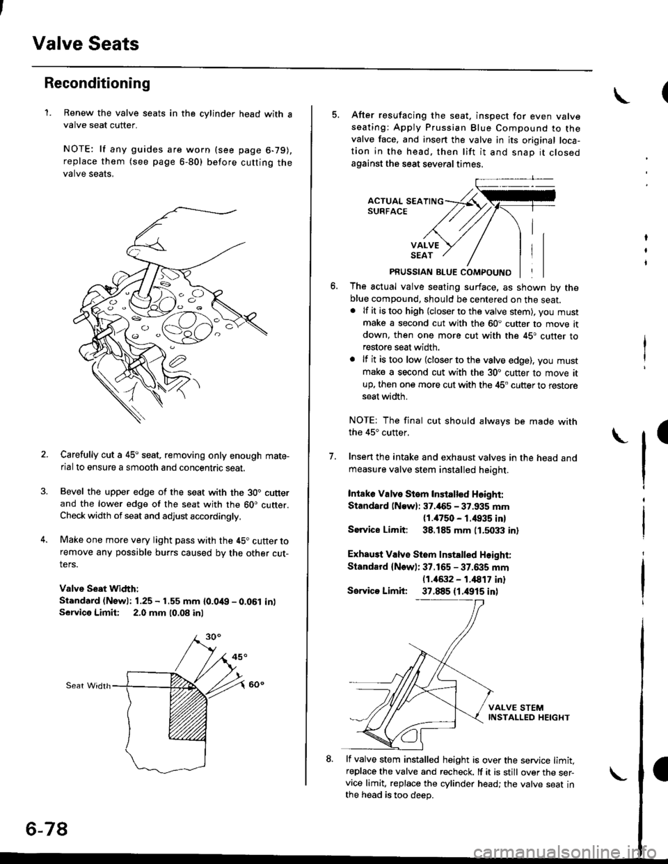
Carefully cut a 45o seat, removing only enough mate-
rial to ensure a smooth and concentric seat.
Bevel the upper edge of the seat with the 30" cutterand the lower edge of the seat with the 60. cutter.Check width of seat and adjust accordingly,
Make one more very light pass with the 45" cutter toremove any possible burrs caused bv the other cut-
ters.
Valve Seat Width:
Standard (Newl: 1.25 - 1.55 mm {0.0't9 - 0.061 in)Service Limii: 2.0 mm 10,08 inl
Sear Widrh
6-78
5. After resufacing the seat. inspect for even valveseating: Apply Prussian Blue Compound to thevalve face, and insert the valve in its original loca-tion in the head. then lift it and snap it closedagainst the seat several times.
PRUSSIAN BLUE COMPOUND
The actual valve seating surface, as shown by theblue compound, should be centered on the seat.. lf it is too high (closer to the valve stem), you mustmake a second cut with the 60. cutter to move itdown, then one more cut with the 45. cutter torestore seat width.
. lf it is too low (closer to the valve edge), you must
make a second cut with the 30. cutter to move itup. then one more cut with the 45. cutter to restoreseat width.
NOTE: The final cut should always be made withthe 45" cutter,
7. Insen the intake and exhaust valves in the head and
measure valve stem installed heioht.
Intaka Valve Stem Installed Height:
Standsrd lNaw): 37.465 - 37.935 mm(1./P50 - r.4935 inl
Sorvice Limit: 38.185 mm 0.5033 in)
Exhau3t Valv€ Stem Installed Height:
Standard (New): 37.165 - 37.6i|5 mm(1.46:t2 - 1.i1817 inl
Servico Limit 37.885 (1.4915 inl
lf valve stem installed height is over the service limit,replace the valve and recheck. lf it is still over the ser-vice limit, replace the cylinder head; the valve seat inthe h6ad is too deep.
(
Page 593 of 2189
Reverse Shift Holder
)
Glearance Inspection
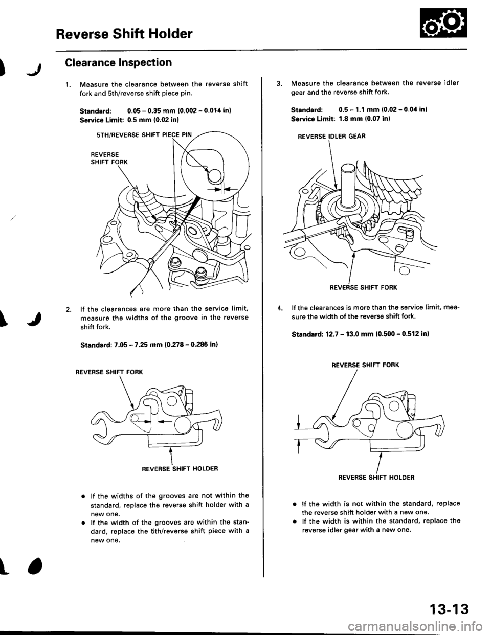
1.Measure the clearance between the reverse shift
fork and sth/reverse shift piece pin.
Standard: 0.05 - 0.35 mm 10.002 - 0.01,1 inl
Service Limit 0.5 mm (0.02 in)
lf the clearances are more than the service limit.
measure the widths of the groove in the reverse
shifi fork.
Standard: 7.05 - 7.25 mm (0.278 - 0.285 inl
lf the widths of the grooves are not within the
standard, replace the reverse shift holder with a
new one.
lf the width of the grooves are within the stan-
dard, replace the sth/reverse shift piece with a
new one,
\
t
REVERSE
REVERSE SHIFT HOLDER
3. Measure the clearance between the reverse idler
gear and the reverse shift fork.
Standard: 0.5- 1.1 mm {0.02 - 0.0,1in)
Service Limii: 1.8 mm 10.07 inl
REVERSE IDLER GEAR
lf the clgarances is more than thg service limit, mea-
sure the width of the reverse shift fork.
Standlrd: 12.7 - 13.0 mm {0.5110 - 0.512 in}
lf the width is not within the standard, replace
the reverse shift holder with a new one.
lf the width is within the standard, replace the
revsrse idler gear with a new one.
REV€RSE SHIFT FORK
REVERSE SHIFT FORK
REVERSE SHIFT HOLOER
13-13
Page 607 of 2189
Synchro Sleeve,
Synchro Hub
MBS Shift Piece InsPection
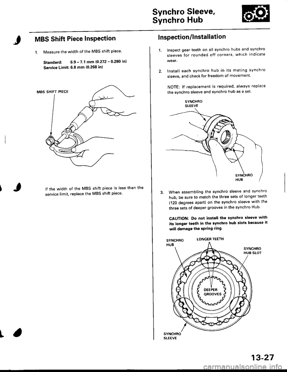
1. Measure the width of the MBS shift piece.
Standard; 6.9 - 7.1 mm 10 272 - 0.280 inl
Service Limit: 6.8 mm {0.268 inl
lf the width of the MBS shift piece is less than
service limit, replace the MBS shift piece'
t
I nspection/l nstallati on
'1.lnspect gear teeth on all synchro hubs and synchro
sleeves tor rounded off corners, which indicate
Install each synchro hub in its mating synchro
sleeve, and check for freedom of movement.
NOTE: lf replacement is required, always replace
the synchro sleeve and synchro hub as a set.
SYNCHROSLEEVE
When assembling the synchro sleeve and synchro
hub, be sure to match the three sets of longer teeth
(120 degrees apart) on the synchro sleeve with the
three sets of deeper grooves in the synchro Hub
CAUTION: Do not install th€ sYnchro sleeve with
its longsr t€sth in the synchro hub slots bocause ii
will damage ths spring ring.
LONGER TEETH
13-27
Page 637 of 2189
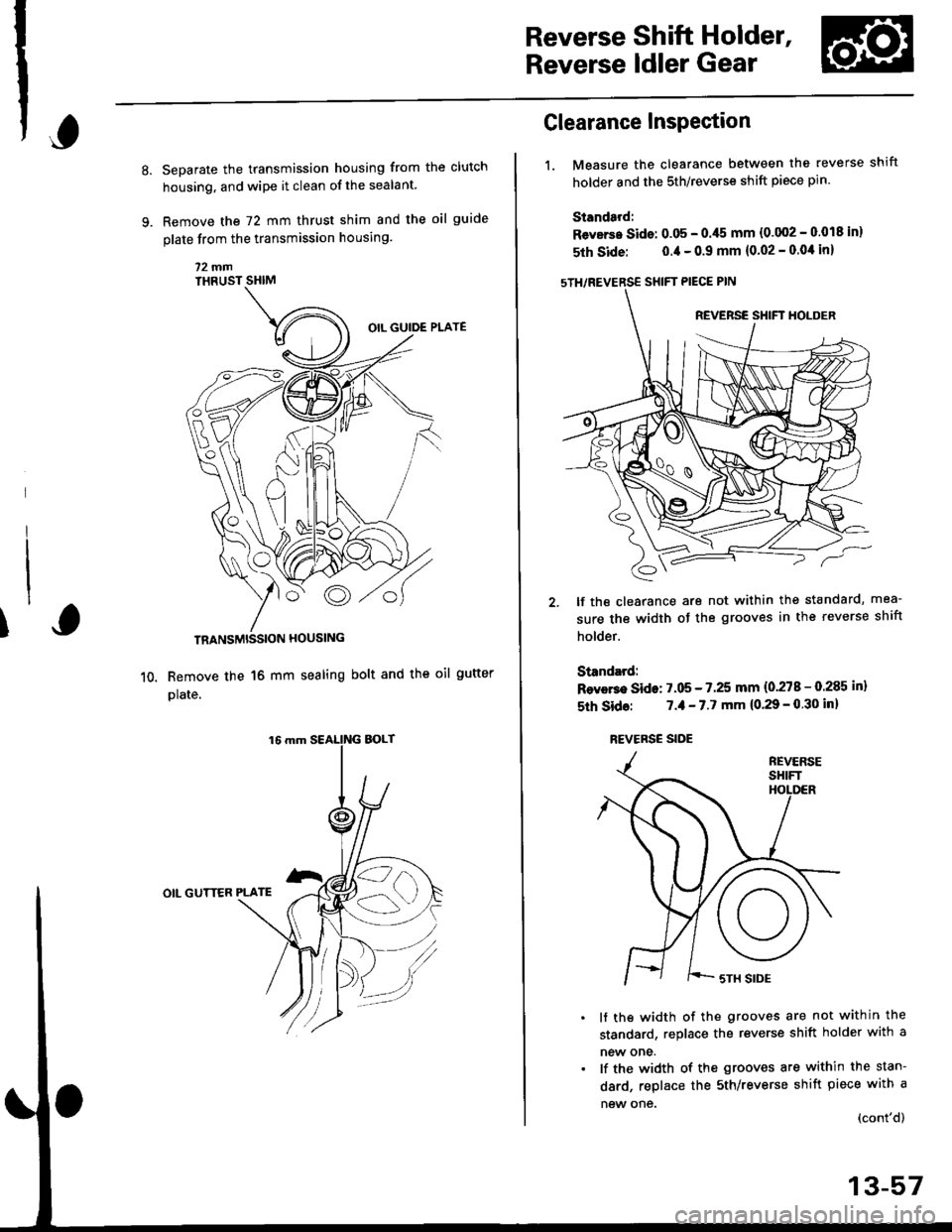
Reverse Shift Holder,
Reverse ldler Gear
Separate the transmission housing from the clutch
housing, and wipe it clean of the sealant.
Remove the 72 mm thrust shim and the oil guide
plate from the transmission housing
72fifiTHRUST SHIM
TRANSMISSION HOUSING
Remove the 16 mm sealing bolt and the oll gutter
plate.
OIL GUTTER PLATE
fi
1.
Clearance Inspection
Measure the clearance between the reverse shift
holder and the 5th/reverse shift piece pin
Standard:
Revsrs. Sids: 0.05 - 0./t5 mm {0'002 - 0.018 in}
5th Side: 0.4 - 0.9 mm (0.02 - 0.0'l in)
sTH/REVERSE SHIFT PIECE PIN
lf the clearance are not within the standard, mea-
sure the width of the grooves in the reverse shift
holder.
Standard:
Rsvers€ Side: 7.05 - 7.25 mm (0'278 - 0.285 in)
5th Sid6: 7.,1- 7.7 mm (0.29 - 0 30 inl
REVERSE SIDE
lf ths width of the grooves are not within the
standard, replace the reverse shift holder with a
new one.
lf the width of the grooves are within the stan-
dard, replace the sth/reverse shift piece with a
new one {cont'd)
13-57
Page 638 of 2189
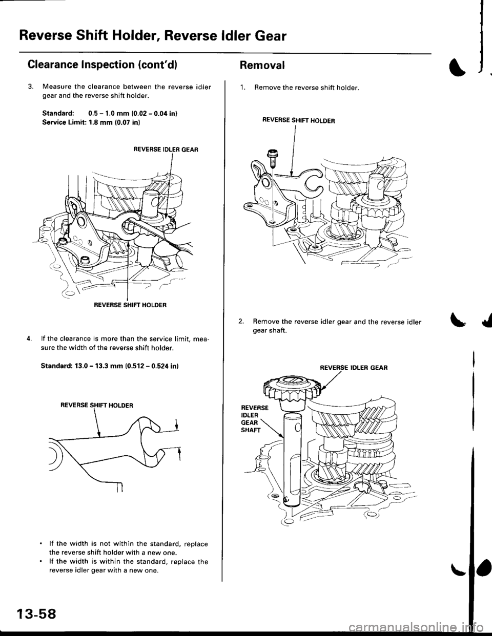
Reverse Shift Holder, Reverse ldler Gear
Clearance Inspection (cont'dl
3. Measure the clearance between the reverse
gear and the reverse shift holder.
Standard: 0.5 - 1.0 mm 10.02 - 0.04 inl
Service Limit: 1.8 mm (0.07 inl
id ler
lf the clearance is more than the service limit. mea,
sure the width of the reverse shift holder.
Standard: 13.0 - 13.3 mm (0.512 - 0.524 in)
lf the width is not within the standard, replace
the reverse shift holder with a new one.
lf the width is within the standard, replace the
reverse idler gear with a new one.
REVERSE SHIFT HOLDER
13-58
Removal
1. Remove the reverse shift holder.
Remove the reverse idler gear and the reverse idlergear shaft.
REVERSE SHIFT HOLDEB
REVERSEIDLER
Page 639 of 2189
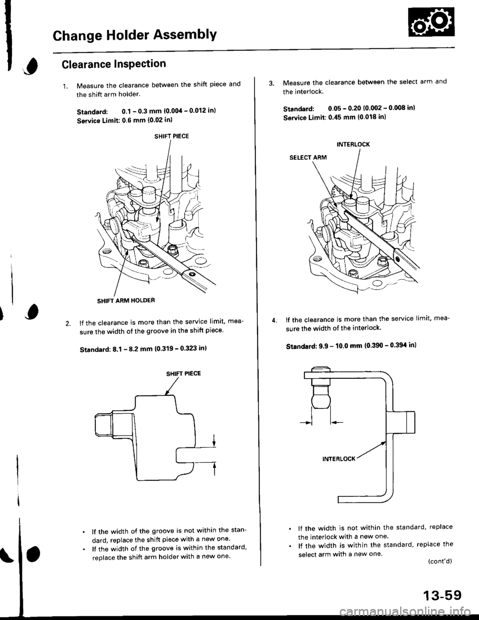
Change Holder AssemblY
,Glearance InsPection
1.Measure the clearance between the shift piece and
the shift arm holder.
Standard: 0.1 - 0.3 mm {0.004 - 0.012 in)
service Limit: 0.6 mm {0.02 in)
lf the clearance is more than the service limit, mea-
sure the width of the groove in the shift piece'
Standard: 8.1 - 8 2 mm {0'319 - 0.323 in}
lf the width of the groove is not within the stan-
dard, replace the shift piece with a new one'
lf the width of the groove is within the standard,
replace the shift arm holder with a new one'
SHIFT PIECE
SHIFT ARM HOLDER
SHIFT PIECE
4.
3. Measure the clearance between the select arm and
the interlock.
Standard: 0.05 - 0.20 10 002 - 0.008 inl
Service Limit:0.45 mm (0.018 inl
lf the clearance is more than the service limit, mea-
sure the width of the interlock.
Standatd: 9.9 - 10.0 mm (0.390 - 0.39't in)
lf the width is not within the standard, replace
the interlock with a new one.
lf the width is within the standard, replace the
select arm with a new one.(cont'd)
INTERLOCK
13-59
Page 641 of 2189
UO
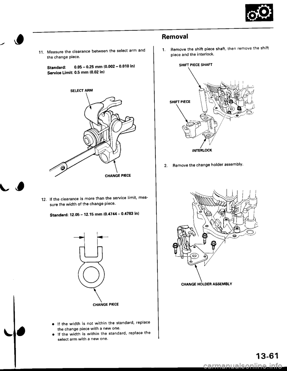
11. Measure the clearance between the select arm and
the change Piece.
Standard: 0.05 - O'25 mm 10'002 - 0'010 in)
Servica Limii: 0.5 mm {0.02 in)
lf the clearance is more than the service limit, mea-
sure the width of the change Plece.
Standard: 12.05 - 12.15 mm {0.47'|{ - 0 47tI| inl
CHANGE PIECE
lf the width is not within the standard, replace
the change Piece with a new one'
lf the width is within the standard, replace the
select arm with a new one.
't2.
a
a
SELECT ARM
Removal
1. Bemove the shift piece shaft. then remove the shift
piece and the interlock.
SHIFT PIECE SHAFT
INTERLOCK
2. Remove the change holder assembly'
13-61
Page 646 of 2189
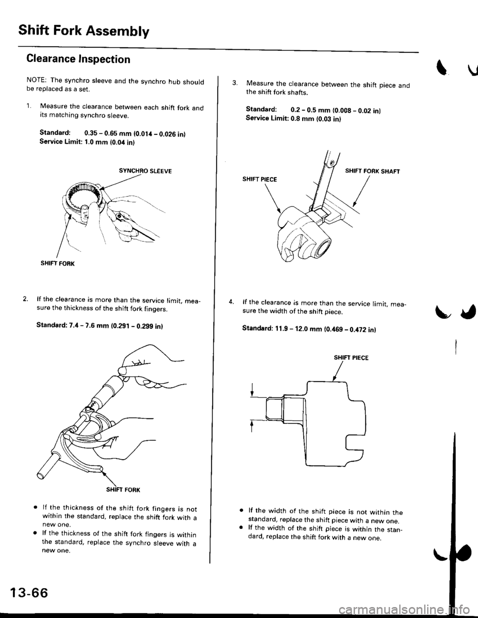
Shift Fork Assembly
Clearance Inspection
NOTE: The synchro sleeve and the synchro hub shouldbe replaced as a set.
1. Measure the clearance between each shift fork andits matching synchro sleeve.
Standard: 0.35 - 0.65 mm {O.Olit - 0.026 inlService Limit: 1.0 mm t0.04 inl
SHIFT FOBK
lf the clearance is more than the service limit. mea_sure the thickness of the shitt fork finoers.
Standard: 7.4 - 7.6 mm (0.291 - 0.299 in)
lf the thickness of the shift fork frngers rs notwithin the standard, replace the shift fork with anew one.
lf the thickness of the shift fork fingers is withinthe standard, replace the synchro sleeve with a
13-66
3. Measure the clearance between the shift piece andthe shift fork shafts.
Standard: 0.2 - 0.5 mm (0.008 - 0.02 inlService Limit: 0.8 mm {0.03 in)
lf the clearance is more than the service limit. mea-sure the width of the shift Diece.
Standard: 11.9 - 12.0 mm (0.469 - 0.it72 in)
lf the width of the shift piece is not within thestandard, replace the shift piece with a new one.lf the width of the shift piece is within the stan_dard, replace the shift fork with a new one.
t,
SHIFT PIECE
Page 832 of 2189
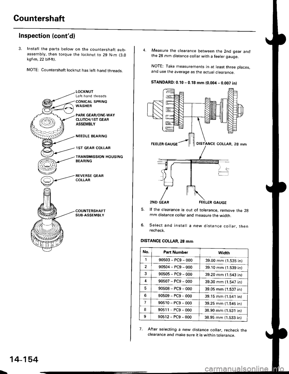
Gountershaft
Inspection (cont'dl
3. Install the parts below on the countershaft sub-assembty, then torque the locknut to 29 N.m (3.0kql.m , 22 blf.ftt .
NOTE: Countershaft locknut has left hand threads.
(=)-----'
v
LOCKNUTLeft hand threads
CONICAL SPRINGWASHER
PARK GEAR/ONE.WAYCLUTCH/1ST GEARASSEMBLY
NEEOLE BEARING
.I ST GEAR COLLAR
TRANSMISSION HOUSINGBEARING
REVERSE GEARCOLLAR
\
14-154
4. Measure the clearance between the 2nd gear andthe 28 mm distance collar with a feeler gauge.
NOTE: Take measurements in at least three places.and use the average as the actuar ctearance.
STANDAFD: 0.10 - 0.18 mm {0.004 - 0.002 inl
lf the clearance is out of tolerance. remove the 2gmm distance collar and measure the width.
Select and install a new distance collar, thenrecheck.
DISTANCE COLLAR, 28 mm
7. Afret selecting a new distance collar, recheck theclearance and make sure it is within tolerance.
OISTANCE COLLAR, 28 mm
No.Part Numb€rwidrh
190503-PCg-00039.00 mm (1.535 in)
290504-PCg-00039.10 mm { 1.539 in)
90505-PCg-00039.20 mm (1.543 in)
90507-PCg-00039.30 mm {1.547 in)
90508-PC9-00039.05 mm (1.537 in)
90509-PCg-00039.15 mm (1.541 in)
790510-PCg-00039.25 mm ( 1.545 in)
I90511-PCg-00038.90 mm (1.531 in)
90512-PCg-00038.95 mm (1.533 in)