123 HONDA CIVIC 2000 6.G Owner's Manual
[x] Cancel search | Manufacturer: HONDA, Model Year: 2000, Model line: CIVIC, Model: HONDA CIVIC 2000 6.GPages: 2189, PDF Size: 69.39 MB
Page 414 of 2189
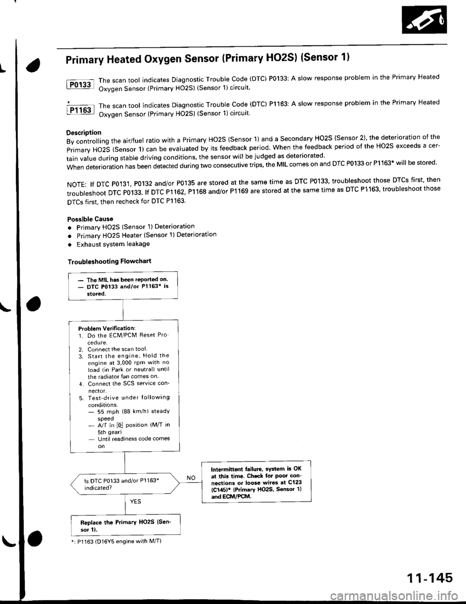
Primary Heated Oxygen Sensor (Primary HO2S) (Sensor 1l
The scan tool indicates Diagnostic Trouble Code (DTC) P0133: A slow response problem in the Primary Heated
Oxygen Sensor {Primary H02S) (Sensor 1) circuit.
The scan tool indicates Diagnostic Trouble code (DTC) Pl163: A slow response problem in the Primary Heated
Oxygen Sensor (Primary HO2S) (Sensor 1)circuit
Description
By controlling the airlfuel ratio with a Primary Ho2S {Sensor 1) and a secondary HO2S {Sensor 2), the deterioration of the
primary HO2S (Sensor 1) can be evaluated by its feedback period. when the feedback period of the Ho2s exceeds a cer-
tain value during stable driving conditions, the sensor will be judged as deteriorated
when deterioration has been detected during two consecutive trips. the MIL comes on and DTC P0133 or P1163* will be stored'
NOTE: tf DTC P0131, P0132 and/or P0135 are stored at the same time as DTC P0133, troubleshoot those DTCS first' then
troubleshoot DTC P0133. lf DTC Pl 162, P1168 and/or P1169 are stored at the same time as DTC P1163, troubleshoot those
DTCS first, then recheck for DTC Pl163.
Possible Cause
o Primary HO2S (Sensor 'l) Deterioration
o Primary HO2S Heater (Sensor 1)Deterioration
. Exhaust system leakage
Troublsshooting Flowchart
tFol3al
I P1163
- The MIL has been reported on- DTC P0133 and/or Pl163* is
stored,
Problem Verilication:1. Do the ECM/PCM Reset Pro
cedure-2. Connect the scan tool
3. Start the engine. Hold the
engine at 3,000 rpm with no
load (in Park or neutral) until
the radiator fan comes on
4. Connect the SCS service con-
nector.5. Test-drive u nder Iollowing
conditions.- 55 mph (88 km/h) steadyspeed- A/f in D position {M/T in
5th gear)
Until readiness code comes
lntermittent failure, 3Y3tem i3 OK
at thi3 time. Ch.ck lol Poor con-
ncctions or loosc wiros at C123
{C145)! lPrimary HO2S, Sensor 1l
and ECM/PCM.
Replace th6 Prim.ry HO2S (Sen'
sor 11.
*: P'l163 (D16Y5 engine with M/T)
11-145
Page 418 of 2189
(From page 11 148)(From page 11'148)
Roplac€ th€ Primary HOzS (Sen'
sor 11.ls there lessthan 2.8 V?
Substitute a known-good ECM
and recheck. lf symptom/indica'
tion goes awav, replace th€ odgi'
nalECM.
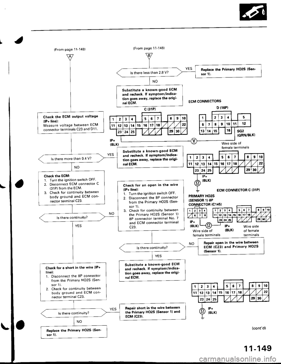
Check the ECM oulput voltage
(lP+ linel:Measure voltage between ECM
connector terminals C23 and D11
Substitute a known-good ECM
and recheck f symptom/indica-
tion goes awaY, replace the origi_
nal ECM.
ls there more than 0.4 V?
Check the ECM:1. Turn the ignition switch OFF.
2. Disconnect ECM connector C(31Plfrom the ECM.
3. Check for continuity between
body ground and ECM con-
nector terminal C23
Check fot an oPen in tha wire
llP+ linel:1. Turn the ignition switch OFF.
2. Disconnect the 8P connoctor
from the Primary HO2S (Sen-
sor'l).3. Check for continuity between
the PrimarY HO2S (Sensor 1)
8P connector terminal No. 7
and ECM connector termrnal
c23.
Repair open in the wire belween
ECM {C231 and Primary HO2S
{Sensor 11.
Substitute a known_good ECM
and r6check. lf symPlom/indica'
tion goos away, replace the odgi-
nalECM.
Check for a short in the wire llP+
line):1. Disconnect the 8P connector
from the Primary HO2S {Sen'
sor 1),2. Check for continuity between
body ground and ECM con-
nector terminal C23.
Repair short in lhe wire belween
the Primary HO2S (Sensor 'l) dnd
ECM {C23).
Replace the Primary HO2S (Sen'
sor 1).
sG2(GRN/BLKI
Wire side offemale termanals
PRIMARY HO2S(SENSOR 1l8PcoNNECTOR lC1a5l
lP+(BLK)
Wire side of
female termrnalsof femaleterminals
NO
(cont'd)
123a68910
111213141516171822
2125a30
I lP+
6) tBrK)
ECM CONNECTOR C {31P}
23a67II10
1112131l15161118,422
232a25A30
A lP+Ij/ IBLK)
11-149
Page 421 of 2189
PGM-FI System
IiT-"-w Heated 9{ygglSensor (primary HO2SI (Sensor 1)(Dl6Y5 engine with M/Tl lconr'd)
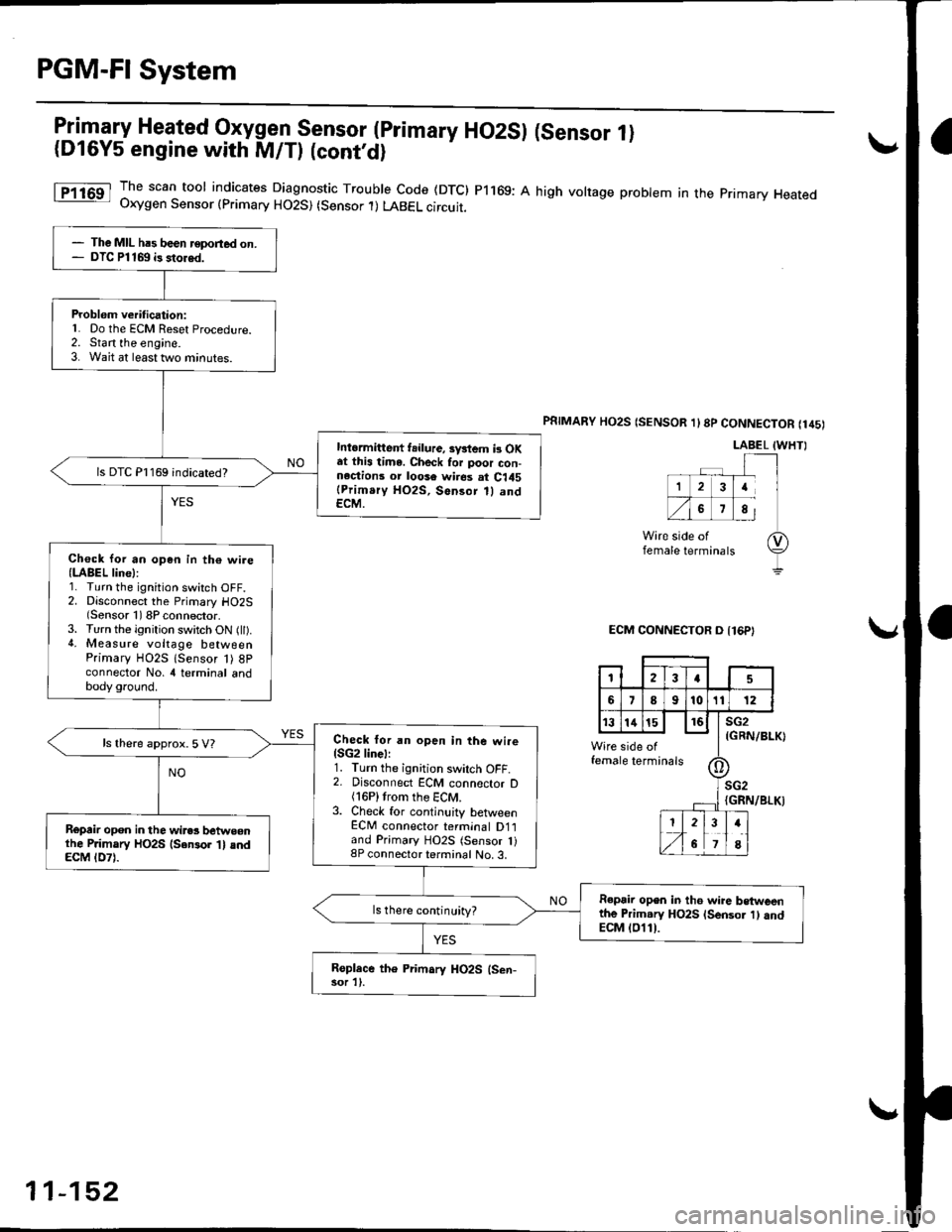
1T1163 Ih" scan tool indicates Diagnostic Trouble code (DTc) P1169: A high volrage probtem in the pnmary Heated- Uxygen Sensor {primary HO2S) (Sensor .l) LABEL circuit.
PSTMARY HO2S (SENSOR 1l8p CONNECTOR (145)
LABEL IWHTI
ECM CONNECTOR O {16P}
(GRN/BLK)
female
IGRN/BLKI
- The MIL hrs been reported on.- DTC Pl169 i3 stored.
Problem verification:L Do the ECM Reset Procedure.2. Start the engine.3. Wait at least two minutes.
Intormittent f.ilure, sv*em b OKat this time. Check for poor con-n.ctions or loose wires at C145(Prim.ry HO2S, Sensor 1l andECM.
ls DTC P1169 indicated?
Ch€ck Ior an op6n in th€ wire(LABEL line):1. Turn the ignition switch OFF.2. Disconnect the Primary HO2S(Sensor 1) 8P connector.3. Turn the ignition switch ON (ll).4. Measure voltage betweenPrimary HO2S lsensor 1) 8Pconnector No, 4 terminal andbody ground.
Check lor an open in the wire{SG2linel:1. Turn the ignition swilch OFF.2. Disconnect ECM connector D(16P)trom the ECM.3. Check for continuity betlveenECM connector terminal D1land Primary HO2S (Sensor 1)8P connector terminal No. 3.
ls there approx. 5 V?
Ropair opon in the wires betweonlhe P.imary HO2S {Sensor 't} andECM tD7l.
R€pair open in th6 wire betweenthe Primary HO2S lsensor 1) andECM (011).
ls there continuity?
Roplace the Primary HO2S (Sen-sor 1).
123a5
689101t12
t3141516sG2
side ofe terminalstll
II-- rl
;G2
I2
6
34
8
11-152
Page 426 of 2189
tFo135l
iPol4tl
Heated Oxygen Sensor (HO2SI Heater
('96 - 98 Mbdels,'99 - 00 Dl6Y5 engine with M/Tl
*: p0141 (To page 11-158)**: D'16Y8 engane
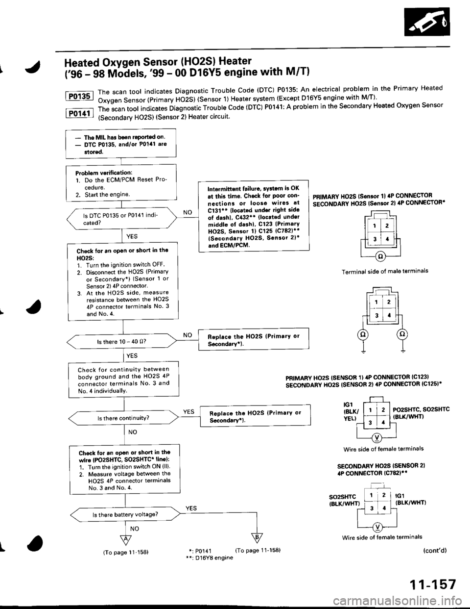
The scan tool indicates Diagnostrc Trouble code (DTC) P0135: An electrical probl€m in the Primary Heated
Oxygen Sensor (Primary HOiS) (Sensor 1) Heater system (Except D16Y5 engine with M/T)'
The;can tool indicates Diagnostic Trouble code (DTC) P0141: A problem in the secondary Heated oxygen sensor
(secondarv HO2S) (Sensor 2) Heater circuit.
PRIMARY HO2S (Son.or 1l aP CONNECTOR
SECoNDARY HO2S tsensor 2l ilP CONNECTORT
Terminal side of male terminals
PRIMARY HOzS (SENSOR 1) 4P CONNECTOR ICl23I
SECONDARY HO2S ISENSOR 2) 4P CONNECTOR {C125I*
PO2SHIC, SO2SHTCIBLK/WHT)
Wire side of female terminals
SECONDARY HO2S ISENSOR 2),tP CONNECTOR 1C782)'*
so2sHTC{BLK/WHT)
Wire side oI female terminals
I(cont'd)
11-157
- The MIL h.s boen Jeponed on.- DTC P0135, and/or Polal .re
stoled.
Problem verificationl
1. Do the ECM/PCM Reset Pro-
ceduae,2. Start the enginelniermittent tailura, sYttam i! OK
at thi3 time, Chsck for Poor con'
neciion3 or loose wilG3 at
C131** (locat.d undo. right sido
ot dashl, C{32** (loc.ted under
middle ol dashl, C123 (PrimarY
HO2S. Sansor 1) C125 lc782l*r
{Socondery H02S, Sonsor 2l'
and EcM/PcM.Check for an open or 3hort in tho
HO25:1. Turn the ignition switch OFF.
2. Disconnect the HO2S (Primary
or Secondary*) (Sensor 1 or
Sensor 2) 4P connector'3. At the Ho2s side, measure
resistance between the HO2S
4P connector terminals No. 3
and No.4.
ls there 10 - 40 0?
Check for continuity between
body ground and the HO2S 4P
connector terminals No. 3 and
No.4 individually
Chock for an oPen ot short in tho
wire |PO2SHTC, SO2SHTC* linol:
1. Turn the ignition switch ON (ll).
2. Measure voltage between the
HO2S 4P connector terminalsNo.3 and No.4.
(To page 11'158)
Page 427 of 2189
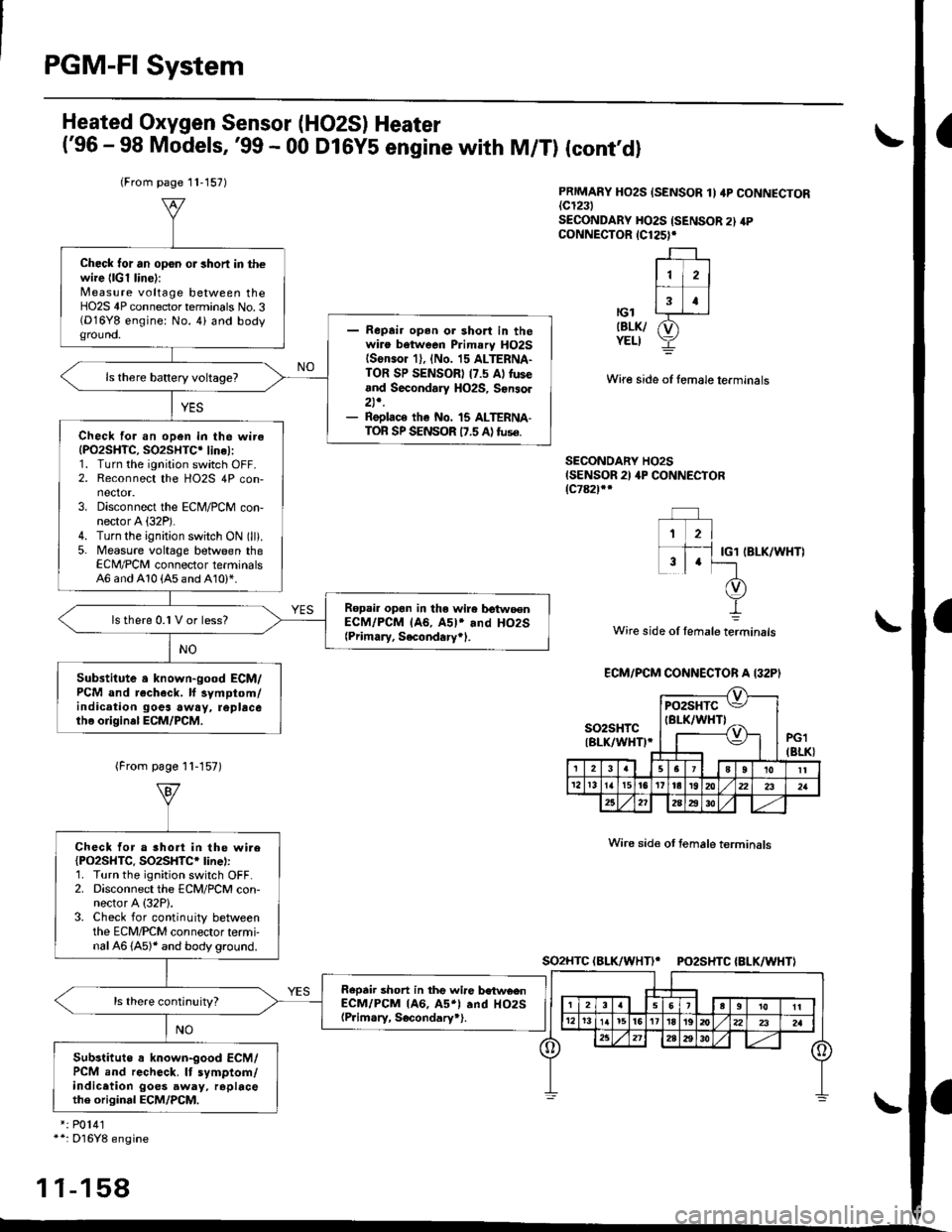
PGM-FI System
a
a
Heated Oxygen Sensor (HO2S) Heater
('96 - 98 Models,'99 - 00 D16Y5 engine with M/T) (cont'dl
PRIMARY HO2S {SENSOR 1I 4P CONNECTOR{c1231SECONDARY HO2S {SENSOR 2} 4PcoNNECTOR 1C125)r
r-l --'1
ll i2l
f;T;ttcl|BLK/ &)YELI Y
Wire side of fomale lerminals
SECONDARY HO2SISENSOR 2) 4P CONNECTOR{c78ilf
IBLK/WHT)
Wire side of lemale terminals
(From page 11-157)
Wire sid€ ot temale terminals
SO2HTC(BLK/WHTI* PO2SHTC{BLK/WHTI
*: P0141*+: Dl6Y8 engine
11-158
(From page 11-157)
Check tor an op6n or 3hoft in thewire {lGl lin6):Measure voltage between theHO2S 4P connector terminals No.3(D16Y8 engine: No. 4) and bodyground.- Repair open or shon in thewire between Primary HO2Slson.or 1), {No. 15 ALTERNA-TOR SP SENSORI (7.5 Al fuseand Secondary HO2S, Sonsol2t,.- Replace the No. 15 ALTERNA-TOR SP SENSOR 17.5 A) tuse.Check for an open in the wireIPO2SHTC, SO2SHTC' linel:1. Turn the ignition switch OFF.2. Reconnect the HO2S 4P con-nector.3. Disconnect the ECM/PCM con-nector A (32P).
4. Turn the ignition switch ON (ll).
5. Measure voltage between theECM,/PCM connector terminals46 and 410 {A5 and A10)*.
Ropail opan in the wire b€twoenECM/PCM lA6, A5l* and HO2S{Primary, Secondary+1.
ls there 0.1 V or less?
Substitute a known-good ECM/PCM and recheck. ll symptom/indication goes awry, repbcetho origin.l ECM/PCM.
ECM/PCM CONNECTOR A I32P)
so2sHrc ItBLK/WH0.J
pozsxtc E/
IBI-K/WHTI ^,-----{v}-|.=,|I
PG1IBLK}3u I JsTgT roll12r3t5t6Ittar920z2l 2321
25272A2i3o
Check tor a short in the wire{PO2SHTC. SO2SHTC* line):'1. Turn the ignition switch OFF.2. Disconnect the ECM/PCM con-nector A (32P1.
3. Check for continuity betweenthe ECM/PCM connector termi-nal 46 (A5)* and body ground.
Repair short in thg wire betwe€nECM/PCM lA6, A5*l .nd HO2S(P.im.ry, Socondary*).
Substitute a known-good ECM/PCM and recheck. It symptom/indicetion goes away, rophcethe original ECM/PCM.
Page 428 of 2189
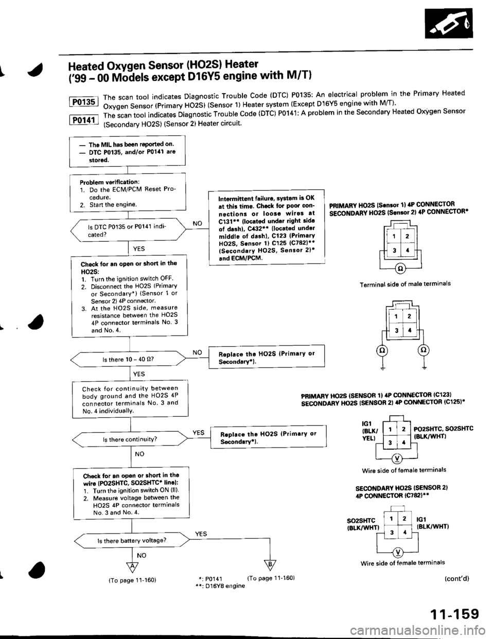
IHeated Oxygen Sensor (HO2S) Heater
i'ss - oo Mb-dels except D16Y5 engine with M/Tl
The scan toot indicates Diagnostic Trouble Code (DTC) P0135: An electrical problem in the Primary Heated
Oxygen Sensor (Primary ttOiS) (Sensor 1) Heater system {Except D15Y5 engine with M/T)'
The
-scan tool indicates Diagnostic Trouble Code (DTC) P0141; A problem in the Secondary Heated Oigen Sensor
(Secondarv HO2S) {Sensor 2) Heater circuit
Fo13sl
Fol11l
lntermiftent failuro, sYstom b OK
at thit limo. Ch6ck lor Poor oon'
nectiont or looso wita! at
C131'* {loc.tod und.t right ido
ol drshl, C432'* (located undel
middlo of dashl, C123 (PrimarY
HOzS, Sensor 1) C125 (Ct82lr'
(socondary HO2S, Sensor 2)t
.nd ECM/PCM.
PRIMAFY HO2S ls.n.or ll rrP CONNECTOR
SECOITIDARY HO2S (Srn.ol21 4P CONNECTOR'
Terminal side of male terminals
PRIMARY HO2S {SENSOR 1} ilP @NI{ECTOR lc123l
sEcoNDARY HO2S ISENSOR 2) aP @NNECTOR (C125)'
3l-, l-tl-t Fo2sHrc. so2sHrc
ver.t l ^-1 .'l {BLK/wHrl
11 '!'l-l
| --=- Iu----{v)'---..-'
Wire side of {emale terminals
SECO'TIDARY Ho2S (SENSOR 2,
4P CONNESTOR {C7&llt'
so2sHTc(BLKnflHTlIBLK/WHT)
(cont'd)
1 1-159
Wire side oI female terminals
r: p0141 {To page 11-160}**: D16Yg engine
- The MIL has been reponed on.- DTC P0135. and/or P0141 are
storod.
Problem vorification:1. Do the ECM/PCM Reset Pro-
cedute.2. Stan the englne.
Chock foi an open or short in the
HO25:1. Turn the ignition switch OFF
2. Disconnect the HO2S (Primary
or Secondary*) lSensor 1 or
Sensor 2) 4P connector'
3. At the H02S side, measure
resistance between the HO2S
4P connector terminals No. 3
and No.4.
ls there 10 - 40 n?
Check for continuity between
body ground and the HO2S 4P
connector terminals No. 3 and
No.4 individuallY.
Check for an opon or short in lho
wire (PO2SHTC, SO2SHTC+ line):'1. Turn the ignition switch ON (ll).
2. Measure voltage between the
H02S 4P connector termlnalsNo.3 and No.4.
{To page 11-160}
Page 429 of 2189
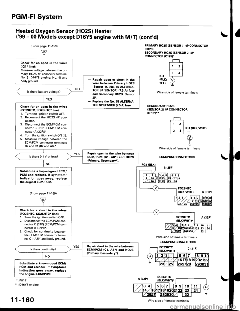
PGM-FI System
Heated Oxygen Sensor (HO2S) Heater
('99 - 00 Models except D16Y5 engine with M/T)
(From page 11-159)
Substitute a known-good ECM/PCM and recheck. lf symptom/indication goes away, replacethe origin.l ECM/PCM.
(cont'dl
PRIMARY HO2S ISENSOR 1I 4P CONNECTOB{c123)SECONDANY HO2S ISENSOR 2} 4PcoNNECTOR (C125)*
-r--r ,
lr zl
-f-13 4llc'l L--r-J-r
relxr p1YELI Y
Wire side of temale terminals
SECONDARY HO2S(SENSOR 21 4P CONNECTOR{c782}rr
IG1 IBLK/WHT)
NO
Wire side of female telminals
ECM/PCM CONNECTORS
Wire side of female terminals
ECM/FCM CONNECTORS
*: P0141**: Dl6Y8 engine
1 1-1 60
Check for an open in the wires{lGl* line}iMeasure voltage between the primary HO2S 4P connector terminalNo. 3 (D16Y8 engine: No. 4) andbody ground.- Repeir open or shon in thewire between Primary HO2Slsensor 1), {No. 15 ALTERNA-TOR SP SENSOR) (7.5 A) fus€and Secondary HO2S, Sensor2t,.- ReDlace the No. 15 ALTERNA-TOR SP SENSOR {7.5 A tuse.
ls there battery voltage?
Check ,or an open in the wires(PO2SHTC, SO2SHTC' linel:1. Turn the ignition switch OFF.2. Reconnect the HO2S 4P con-nector,3. Disconnect the ECN4/PCM connector C (31Pi (ECM/PCM con-nector A (32P))i.
4. Turn the ignition switch ON (lli.
5. Measure voltage between theECM/PCM connector terminals82 and Cl 182 and AB)*.
Reprir open in the wirc betwo€nECM/PCM (Cl, A8i) and HO2S(Primary, Secondary+).
ls there 0.1 V or less?
(From page 11 l59i
Check tor a short in the wiresIPO2SHTC, SO2SHTC* linel:1. Turn the ignition switch OFF.2. Disconnect the ECM/PCM con-nector C (31Pi (ECM/PCM connector A (32P)i*.
3. Check tor continuity betweenthe ECM/PCM connector terminal C1 {A8)* and body ground.
Repai. short in the wire b€tweenECM/PCM lcl, A8.l and HO2S(Pdmery, Secondary*1.
Substitute a known-good ECM/PCM end recheck. lf symptom/indication goes away, replacethe o.iginal ECM/PCM.
Wire side of female terminals
Page 467 of 2189
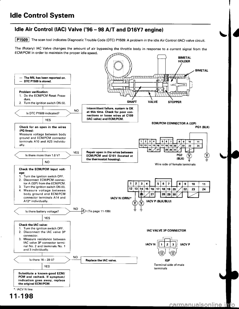
ldle Control System
ldle Air Control (lAC) Valve ('96 - 98 A/T and Dl6Y7 enginel
The (Rotary) IAC Valve changes the amount of air bypassing the throttle body in response to a current signal from theECM/PCM in order to maintain the proper idle speed,
BIMETAL
VALVESTOPPER
1P1509 Thescantool indicates Diagnostic Trouble Code (DTC) P1509: A problem in the idle Air Control (tAC)valve circuit.
ECM/PCM CONNECTOR A I32PIPGl IBLKI
IAC VALVE 3P CONNECIOR
IACV NIACV P
IGP
Terminal side of maleterminals
*: IACV N line
1 1-198
The MIL has b€€n roported on.DTC P1509 is stored.
Problem verification:1. Do the ECM/PCM Reset Proce-oure.2. Turn the ignition switch ON (ll).
Intermittent failura, systom ia OKat this time. Check tor poo. con-noctions or loose wires at C109llAC valve) and ECM/PCM.
ls DTC P1509 indicated?
Check for an opon in the wirer{PG lines):Measure voltage between bodvground and ECM/PCII connectorterminals A10 and A23 individu
Repair op€n in the wires betwoenECM/PCM and G101 llocated attho thermostat housing).
ls there more than 1.0 V?
Chock th€ ECM/PCM inpui volt-agel1. Turn the ignition switch OFF.2. Disconnect ECM/PCM connec-tor A (32P)from the ECM/PCM.3. Turn the ignition switch ON (ll).4. Measu re voltage betweenbody ground and ECM/PCMconnector terminals A14 andA13* individually.
Ch6ck th6 IAC valve:1. Turn the ignition switch OFF.2. Disconnect the IAC valve 3Pconnector,3, Measure resistance betweenIAC valve 3P connector termi-nal No.2 and terminals No. 1and 3 individually.
ls there 16 - 28 g?
Substitute a known-good ECM/PCM and recheck. lf symptom/indication goos away, replaceth€ origin.l ECM/PCM.
SHAFT
rAcv N loRNl*
(To page 11-199)
Wire side of lemale terminals
123a56El011
121314r5161718t9202:22321
272AA30
IACV P {BLK/BLUI
Page 473 of 2189
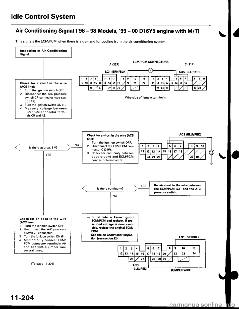
ldle Gontrol System
Air Gonditioning Signal ('96 - 98 Models, '99 - 00 Dl6Y5 engine with M/Tl
a {32P1ECM/PCM CONNECTORS
Wire side of female terminals
c l3lPl
This sjgnals the ECM/PCM when there is a demand for cooling from the air conditioning system.
(To page 11-205)
Check for a short in the wire{ACS line):1. Turn the ignition switch OFF.2. Disconnect the A/C pressure
switch 2P connector {see section 22).3. Turn the ignition switch ON (ll).
4. Measure vo lta ge betweenECM/PCM connector termi-nals C5 and A9.
Check for a .hort in the wi.e {ACSline):1. Turn the ignition switch OFF.2. Disconnect the ECM/PCM con-nector C (3lPi.
3. Check tor continuity betweenbody ground and ECM/PCMconnector terminal C5,
ls there approx. 5 V?
Reotir short in the wi.e betweenthe ECM/PCM lc5l and rhe A/Cpressure switch.
ls there continuity?
- Substitute a known-goodECM/rcM .nd re.fieck. f Dre-scribed voltage is now availtble, replace the original ECft4/PCM,- See the air conditioner inspe-tion ls€e s€ction 221.
Check tor an op€n in the wireIACC lin6l:1. Turn the ignition switch OFF.2. Reconnect the A/C pressure
switch 2P connector.3. Turn the ignition switch ON (ll).
4. Momentarily connect ECM/PCM connector terminals A9and A17 with a jumper wire
LGl IBRN/8LKIACS {BLU/RED)
2361I9't0Itt3a89t0
12't31al5l617t8t920232all12l3l!ai5!617'tE
252l2A2930232a252930
ACS (BLU/BEDI
LGl IBRN/BLKI
123aslslrl lolgl ro lrr I
121314l516y)nltslnl/@) zr I zr I
25271!M1 1-/r
ACC
11-204
IBLK/RED)JUMPER WIRE
Page 476 of 2189
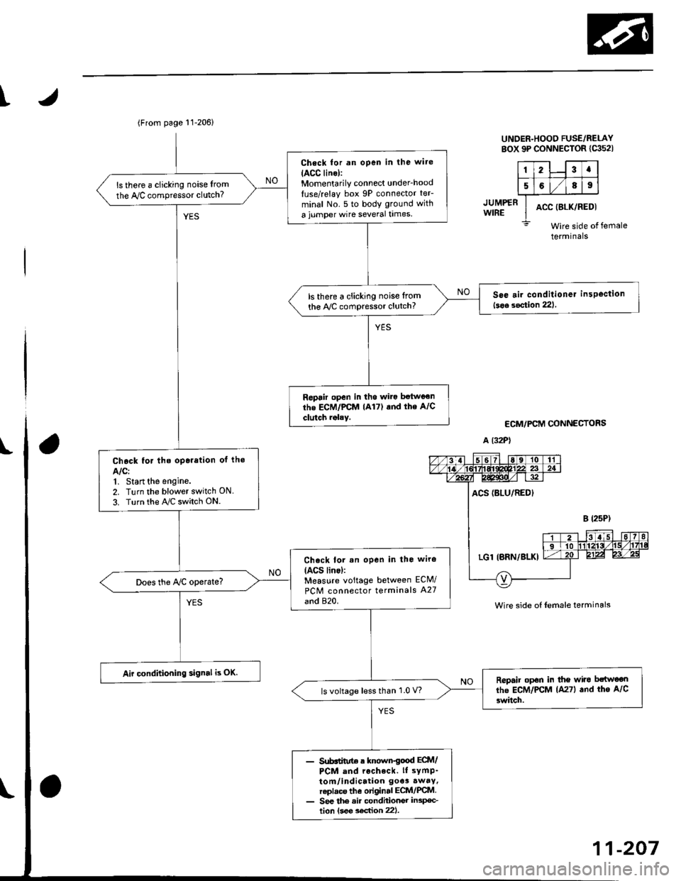
I
JUMP€RWIRE
UNDER-HOOO FUSE/RELAYsox 9P coNNEcroR lca52l
123a
5689
ACC (8LK/REDI
Wire side ofterminals
ECM/PCM CONNECTORS
A (32P1
female
Wire side of {emale terminals
(From page 11-206)
Check for an open in the wite
IACC lino):Momentarily connect under_hood
luse/relay box 9P connector teF
minal No. 5 to body ground with
a jumper wire several times.
ls there a clicking noise from
the Iy'C compressor clutch?
S6e air conditioner insPoction
l3oa section 221ls there a clicking noise lrom
the ly'C compressor clutch?
Ropair open in tho wilo betwg€n
the ECM/PCM lA17) and the A/C
clutch rolay.
Chock for the oporation of lho
AIC:1, Start the engine.
2. Turn the blower switch ON
3. Turn the ray'C switch ON.
Check lor an open in the wiro(ACS lino):Measure voltage between ECM/
PCM connector terminals A27
and 820.
Does the Iy'C operate?
Air conditioning signal is OK.Repair op6n in the wiro bctwoon
lhe ECM/PCM lA27l and tho A/C
3witch.ls voltage lessthan 1.0 V?
- Sub6iitut€ r known€ood ECtt /PCM and rccheck. ll sYmP-
tom/indication 9oe3.waY,replaca the original ECM/PCM- See the ai. condhionGr in3p€c-tion lsee soc{ion 221.
11-207