alternator HONDA CIVIC 2000 6.G Owner's Manual
[x] Cancel search | Manufacturer: HONDA, Model Year: 2000, Model line: CIVIC, Model: HONDA CIVIC 2000 6.GPages: 2189, PDF Size: 69.39 MB
Page 554 of 2189
\
\
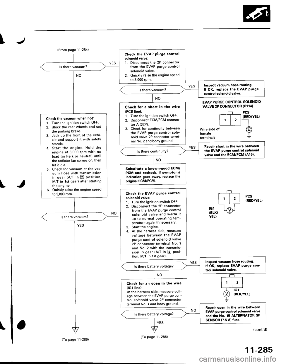
(From page 11-284)
\(cont'd)
11-285
EVAP PURGE CONTROL SOI.INOID
VALVE 2P CONNECTOR IC114I
Wire side otfemaleterminals
?,
I,l,lil?"",,,u
EL,TWYEL)
Check the EVAP pirrge controlsolenoid valvei1. Disconnect the 2P connector
lrom the EVAP purge control
solenoid valve.
2. Ouickly raise the engine speed
to 3,000 rpm.
ls there vacuum?
InsDect vacuum ho56 routing.ll OK, replace the EVAP Purgecontrol solenoid valve.
Chock for a short in the wire(PCS linel:1. Turn the ignition switch OFF
2. Disconnect ECM/PCM connec'
tor A (32Pi.
3. Check for continuity between
the EVAP PUrge control sole
noid valve 2P connector termi
nal No.2 and body ground.
Check the vacuum when hot:
1. Turn the ignition switch OFF
2. Block the rear wheels and set
the parking brake.3. Jack up the front o{ the vehi-
cle and support it with safety
stands,4. Start the engine. Hold the
engine al 3,000 rpm wlth no
load (in Park or neutral) until
the radiator fan comes on, then
let it idle.5, Check for vacuum at the vac-
uum hose with transmissaonin gear (A/T in B Position,M/T in lst gear) after starting
the engrne.6. Ouickly raise the engine speed
to 3,000 rpm.
Reoair short in the wire botween
the EVAP purg€ cor|t]ol solenoid
valve and the ECM/pcM lA15l.ls there continuity?
Substitute a known-good ECM/
PCM and recheck. lf sYmPtom/indication goes eway. repl.c€ the
original ECM/PCM.
Check the EVAP Purg€ control
solenoid valve:1. Turn the ignition switch OFF
2. Disconnect the 2P connector
from the EVAP Purge control
solenoid valve and warm lt
up to normal operating tem_perature again if necessary
3. Stan the engine.4. At the harness side, measure
voltage between the EVAP
Purge control solenoid valve
2P connector terminal No. 1
and No. 2 with the transmission in gear (A,/T in E Posi-tion, M/T in 1st gear).
In3pect vacuum ho3€ touting.
ll OK, replace EVAP Purge con-
lrol aolenoid vtlv€.
Check lo. an open in the wire
llGl linel:At the harness side, measure volt
age between the EVAP Purge con-
trol solenoid valve 2P connectorterminal No. 1 and body groundRepeir open in tho wire between
EVAP purge conttol solenoid valv€
and the No. 15 ALTERNATOR SP
SENSOR (7.5 A fu3e
IBLK/YELI
lTo page 11 286i(To page 11-286)
Page 556 of 2189
I
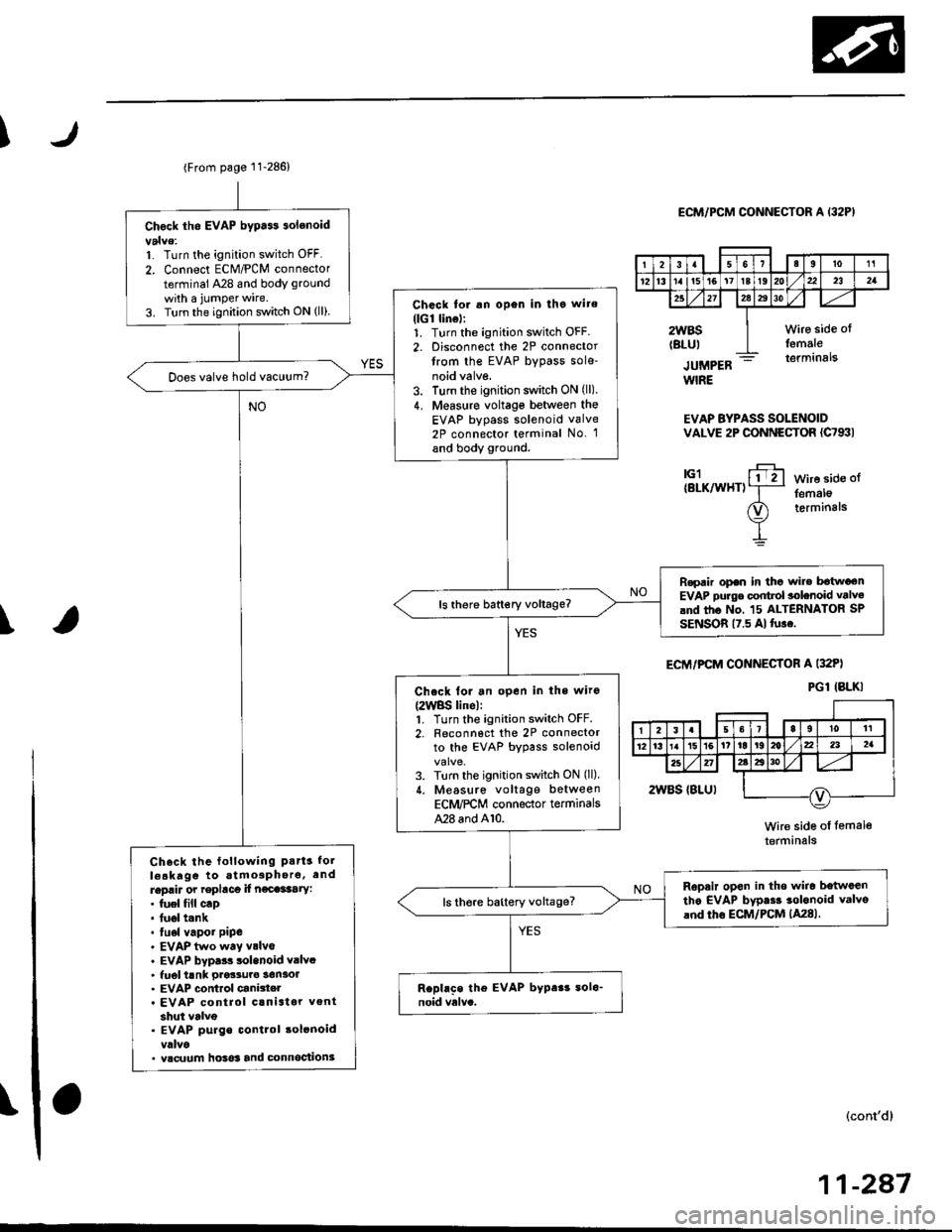
ECM/PCM CONNECTOR A (32P)
2WBS(BLUIWiro side olIemaleterminalsJUMPER _
WIRE
EVAP BYPASS SOLENOIDVALVE 2P CONNECTOR {C793I
Wire side of
femal€terminals
\
ECM/P,CM CONNECTOR a l32Pl
Wir€ side of femaleterminals
(cont'dl
11-2A7
(From page 11-286)
Check the EVAP bypa3s 3olenoid
1. Turn the ignition switch OFF.
2. Connect ECM/PCM connectorterminal A28 and body ground
with a jumper wire.3. Turn the ignition switch ON (ll).ChGck tor an opon in lho wite(lGl lin6l:1. Turn the ignition switch OFF
2. Disconnect the 2P connectortrom the EVAP bypass sole-noid valve.3. Turn the ignition switch ON (ll).
4. Measure voltage between the
EVAP bypass solenoid valve
2P connector terminal No- 1
and body ground.
R.pair open in tha wil€ botwoonEVAP purg. cor|trol 3olenoid valve
.nd tho No. 15 ALTERNATOR SP
SENSOR 17.5 Al tu3e.
Check lor an open in the wire
{2WBS line):l. Turn the ignition switch OFF.
2. Reconnsct the 2P connectorto the EVAP bypass solenoid
3. Turn the ignition switch ON (ll)
4. Measure voltage between
ECM/rcM connector terminalsA28 and Al0.
Ch6ck the following P..ts for
l6akage to atmosPhere, and
roplir or rephco if neca3aary:' fuel fill c.D. tu6l t.nk. tuel vapor pipe. EVAP two way v3lvo. EVAP bypa3! solanoid vtlY., fuel tlnk pra63uro 3on3or. EVAP control canBte.. EVAP control crnistor vent
shut vtlvo. EVAP purgo control lolonoid
. vscuum hoseS and connoction3
Roprir opon in tho wiro betwoen
th. EVAP byp.$ 3ol6noid valve
rnd tho EcM/PcM lA28l.ls there battery voltage?
I2578t011'12tt15t6t8t9202321
2726293o
PGl (BLKI
I
II7l lslel ro lr' I't2r3,"l!j'"EBUP)._3)_!J
Ent ll4al*l 4 l,-'l
2WaS {BLUI
\
Page 559 of 2189
Emission Control System
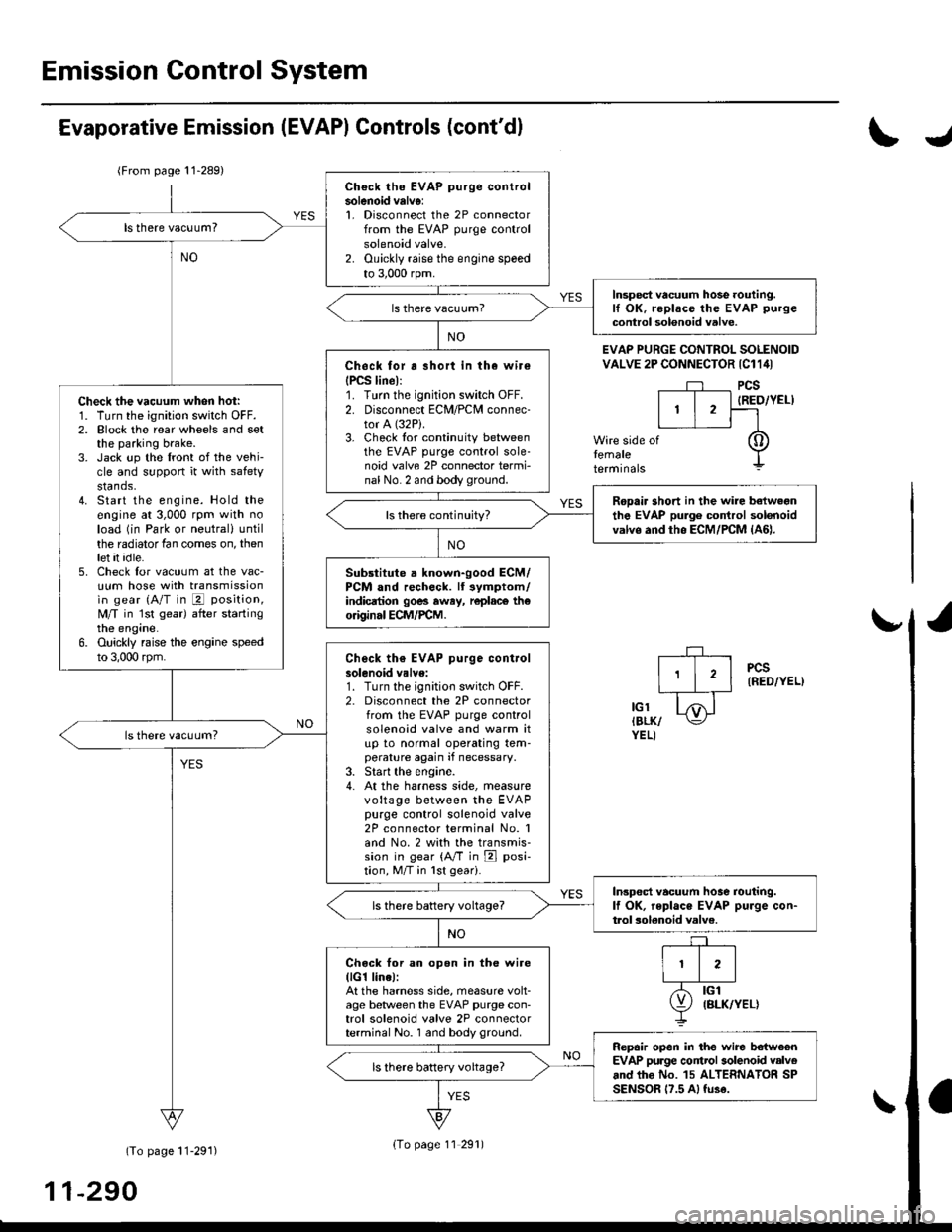
Ch€ck the EVAP purge controlsolenoid valv6:1. Disconnect the 2P connectorfrom the EVAP purge controlsolenoid valve.2. Ouickly raise the engine speedto 3,000 rpm.
Insped vacuum hose routing.lf OK. roplace the EVAP purge
control solonoid valve.
Chock tor r short in the wir€
{PCS line):1. Turn the ignition switch OFF.2. Disconnect ECM/PCM connec-tor A (32P).
3- Check tor continuity betweenthe EVAP purge control sole-noid valve 2P connector termi-nal No. 2 and body ground.
Check the vacuum when hot:1. Turn the ignition switch OFF.2. Block the rear wheels and setthe parking brake.3. Jack up the lront of the vehi-cle and support it with safetystands.4. Start the engine. Hold theengine at 3,000 rpm with noload (in Park or neutrali until
the radiator fan comes on, thenlet it idle.5. Check for vacuum at the vac-uum hose with transmissionin gear (A/T in E position,
lvl/T in 1st gear) after startingthe engine.6. Ouickly raise the engine speedto 3,000 rpm.
Rooair shoft in the wire belwegnthe EVAP pulg6 control solenoidvalvs and tho ECM/PCM {A61.ls there continuity?
Substitute a known-good ECM/PCM and rech6ck. lt 3ymptom/indicrtion 90e3 rway, r6plac6 th€o.iginal ECM/FCM.
Check th€ EVAP purge controlsolenoid valve:1. Turn the;gnition switch OFF.2. Disconnect the 2P connectorfrom the EVAP purge controlsolenoid valve and warm itup to normal operating tem-perature again if necessary.3. Start the engine.4- At the harness side, measurevoltage between the EVAPpurge control solenoid valve2P connector terminal No. 1and No.2 with the transmis-sion in gear {A/T in E posi-tion, M/T in lst geari.
In3pect vacuum hoae routing.lf OK, repl.ce EVAP purge con-trol solonoid valve.ls there battery voltage?
Chock for an open in the wire(lG1 lina):At the harnoss side, measure volt-age beNveen the EVAP purge con-trol solenoid valve 2P connectorterminal No. 1 and body ground.
Repair open in the wire b€lwe€nEVAP purge contrl 3olenoid valv6and lhe No. 15 ALTERNATOR SPSENSOR 17.5 A, fu3e.
ls there battery voltage?
Evaporative Emission (EVAPI Controls (cont'dl
(From page 11-289)
(To page 11-291)
11-290
IJ
EVAP PURGE CONTROL SOLENOIDVALVE 2P CONNECTOR IC114I
PCS
IRED/YEL)
temaletermrnars
of
PCS(RED/YEL)
tGlIBLK/YEL)
{To page 11 291)
Page 561 of 2189
Emission Control System
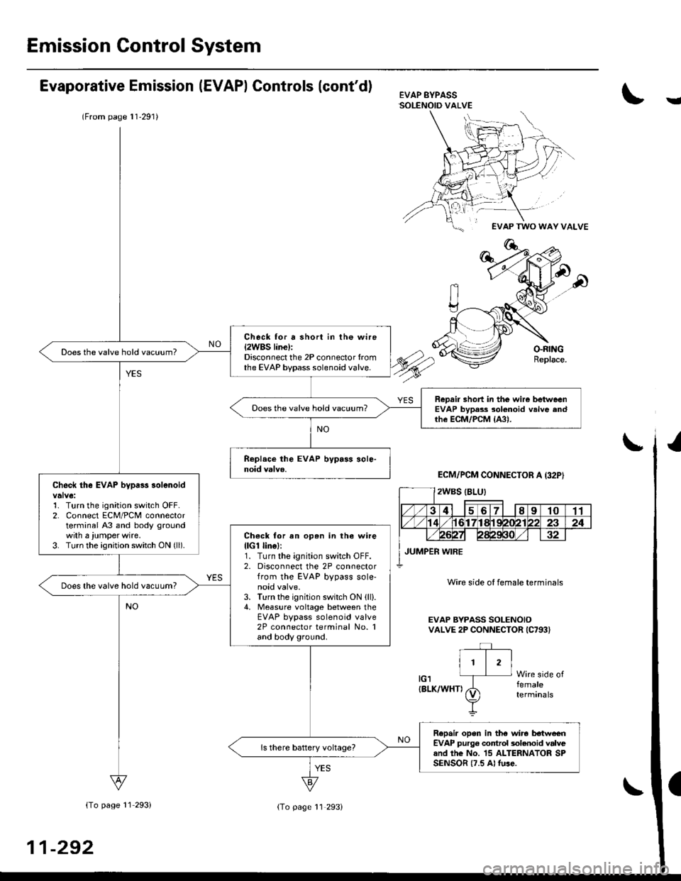
Evaporative Emission (EVAPI Gontrols (cont'd)EVAP BYPASSSOLENOID VALVEY
(From page l1'291)
Check for a short in the wire{2WBS linel:Disconnect the 2P connector {romthe EVAP bypass solenoid valve.
Does the valve hold vacuum?
Repair short in the wire betweenEVAP bypass solenoid velve andrhe ECM/PCM {A3).
Ooes the valve hold vacuum?
Check the EVAP bvpr$ 3olenoid
1. Turn the ignition switch OFF.2. Connect ECM/PCM connectorterminal A3 and body groundwith a jumper wire.3. Turn the ignition switch ON (ll).Ch€ck lor an op.n in the wirellcl linol:1. Turn the ignition switch OFF.2. Disconnect the 2P connectorfrom the EVAP bypass sole-noid valve.3. Turn the ignition switch ON (lll.
4, Measure voltage between theEVAP bypass solenoid valve2P connector terminal No. 1and body ground.
Does the valve hold vacuum?
Repair open in the wir6 b€tw€€nEVAP purg6 control 3olanoid valveand the No. 15 ALTERNATOR SPSENSOR {7.5 A) Iuse.
Wire side ol female terminals
EVAP SYPASS SOLENOIOVALVE 2P CONNECTOR IC793}
tG1{BLK/WHT)
Wire side offemaleterminals
{To page 11 293)
11-292
(To page 11 293i
Page 1473 of 2189
Troubleshooting
ll.
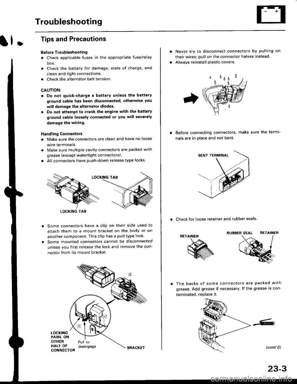
Tips and Precautions
Bef ore Troubleshooting
. Check applicable fuses in the appropriate fuse/relay
box.
. Check the battery for damage, state of charge, and
clean and tight connections.
. Check the alternator belt tension.
CAUTION:
. Do not quick-charge a battery unless the battery
ground cable has been disconneqted, otherwise you
will damage the alternator diodes.
. Do not attempt to crank the engine with the battery
ground cable loosely connecled or you will severely
damage the wiling,
Handling Connectois
. Make sure the connectors are clean and have no loose
wire terminals.
. Make sure multiple cavity connectors are packed with
grease (except watertight connectors)
. All connectors have push-down release type locks.
Some connectors have a clip on their side used to
attach them to a mount bracket on the body or on
another component. This clip has a pulltype lock.
Some mounted connectors cannot be disconnected
unless you first release the lock and remove the con-
nector from its mount bracket.
LOCKINGPAWL ONOTHERHALF OFCONNECTOR
Pull todrsengage
LOCKING TAB
BRACKET
Never try to disconnect connectors by pulling on
their wires; pull on the connector halves instead
Alwavs reinstall plastic covers.
Before connectang connectors,
nals are in place and not bent.
make sure the terml-
. Check for loose retainer and rubber seals.
RETAINER
The backs of some connectors are packed with
grease. Add grease if necessary. lf the grease is con-
taminated, replace it.
(cont'd)
23-3
Page 1486 of 2189

Connector ldentification and Wire Harness Routing
Engine Wire Harness lD16Y5, D16Y8 enginss): '96 - 98 models
Connector or
Torminal
Numbsr of
CavitissLocationConnects toNot€s
c 101c102c103c104c104c105c106c107c108c 109c110c111c112c113c114c115c116cl17c118c119c120cl21
c122c123cl23c124
c125
c127c12Ac129c130c131c132c 133c134c135
c136
c138c139c140c 141c142c 143c144cl44c145c'146cl47
10
1
22
14l4322l0I
2
2
2
2120
3l
14
14
1222
2
2
22
Left side of engine compartmentMiddle of engineMiddle of engineLeft side of engine companmentLeft side of engine compartmentMiddle of engineMiddle of engineMiddle of engineMiddle of engineMiddle of enginefvliddle of engineMiddle of engineMiddle of engineMiddle of engineMiddle of engineMiddle of engineMiddle of engineLeft side of engine compartmentMiddle of engineMiddle of engineMiddle of engineMiddle of engine
Middle of engineMiddle of engineMiddle of engineMiddle of engineMiddle of engineMiddle of engineMiddle of engineMiddle of engineMiddle of engineRight side of engine companmentBehind right kick panelUnder right side of dashUnder riOht side of dashUnder right side of dashUnder right side of dashUnder right side of dashUnder right side of dash
Under right side of dash
Under right side of dash
Middle of engineMiddle ot enginel iddle of engineMiddle of engineMiddle of ongineMiddle of engineLeft side of engine compartmentMiddle of engineMiddle of engineRight side of engine compartmentRight side of engine compartmentRight side of engine compartment
USACanada
Afi
USA
-' (A/r)
Main wire harness (C303)Crankshaft speed fluctuation (CKF) sensorEngine oil pressure switchAlternatorAlternatorNo. 'l fuel injectorNo. 2 fuel injectorNo.3 fuel injectorNo. 4 fuel injectorIAC valveThrottle position (TP) sensorl\4anifold absolute pressure (MAP) sensorIntake air temperature (lAT) sensorPower steering pressure {PSPI switchEVAP purge control solenoid valveJunction connectorJunction conn€ctorVehicle speed sensor {VSS}Countershaft speed sensorEngine coolant temp€rature (ECT) switch ADistributorEngine coolant temperature (ECT) sendingunrtEngine coolant temperature (ECT) sensorPrimary HO2S (sensor'l)Primary HO2S (sensor 1)Back-up light switchLock-up control solenoid valveSecondary HO2S (sensor 2)Mainshaft speed sensorLinear solgnoid valveShift control solsnoid valveStarter solenoidJunction connectorMain wire harnesE (C446)ECM/PCMPCMECMiPCMECM/PCMMain wire harness (C305)
Main wire harness (C305)
Main wire harness (C305)
Knock sensor (KS)IAC valveVTEC solenoid valveVTEC pressure switchEVAP control canister vent shut valveEGR control solenoid valveSecondary gear shaft speed sensorEGR valveEGR valveDrive pulley speed sensorSolenoid connector {CVT)Driven pulley speed sensor
*, (M/T)M/T*" INT\
*, tAtf)
NT:'96 model*,(A,/T):'97 - 98mooets
moqets
M/T
-1 (l,/T)*, (A,/T)-,(4,/T)*1 {M/T)*, (A,/T)*1 (CW)*, (A,T)
T101r102Left side of engine companmentRight side of engine companmentAlternatorUnder-hood fuse/relay boxG 101Middle of engineEngine ground, via engine wire harness
2
*1: Dl6Y5 engine*2: D16Y8 engine*3: D16Y5 (Ay'T), D16Y8 engines
3-16
Page 1488 of 2189
Gonnector ldentification and Wire Harness Routing
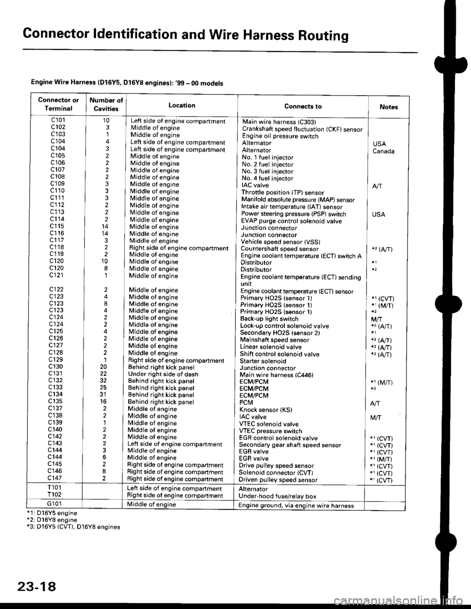
Engine Wire Harness (D16Y5, Dl6Yg engines): ,99 - 00 models
Connectot or
Terminal
Number ot
CavitiesLocationConn€cts toNotes
c'101cl02c103c104c 104c10s
c107c 108c'r09c110c111cl12c113cl14c l15c116cl17c118c119c120cl20c121
c122c123c123cl23cl24c124c125
c127c12Ac129c 130c131cl32c133c 134c135c137c138c 139c 140c142c143c144cl44c145c146c147
103,]
322223332221414322'10
8,l
2484224222120
32
2212223
282
No. 1 luel injector INo.2 fuel injectorNo.3 fuel injector ]No. 4 fuel injector iIAC valve I anThrottle position lTP) sensorManifold absolute pressure {MAP) sensor IIntake air temperature (lAT) sensor IPower steering pressure (PSP)switch USAEVAP purge control solenoid valve ]
Main wire harness 1C303)Crankshaft speed fluctuation (CKF) sensorEngine oil pressure switchAlternatorAlternator
Left side ot engine compartmentlvliddle of engineMiddle of engineLeft side ot engine compartmentLeft side of engine compartmentMiddle of engineMiddle ot engineMiddle of engineMiddle of engineMiddle oI engineMiddle of engineMiddle of engineMiddle of engineMiddle of engineNliddle of engineMiddle of engineMiddle of engineMiddle of engineRight side of engine compartmentMiddle of engineMiddle of engineN4iddle of engineMiddle of engine
Middle of engineMiddle ot engineMiddle ot engineMiddlo of engineMiddle of engineMiddle ot enginelrliddle of engineMiddle of engineMiddle oI engineMiddle ot engineRight side of engine compartmenlBehind right kick panelUnder right side of dashBehind right kick panelBehind right kick panelBehind righr kick panelBehind right kick panelMiddle ot engine[,liddle of engineN4iddle of engineMiddle of engineMiddle oI engineLeft side of engine compartmentMiddle of engineMiddle of engineRight side ol engine compartmentRight side of engine companmentRight side of engine compartment
USACanada
Junction connectorJUnct|On COnnectorVehicle speed sensor lVSS)Countershaft speed sensorEngine coolant temperature {ECT} switch ADistributorDistributorEngine coolant temperature (ECT) sendingunitEngine coolant temperature (ECT) sensorPrimary H02S (sensor 1)Primary HO2S (sensor 1)Primary HO2S lsensor 1)Back-up light switchLock'!p control solenoid valveSecondary HO2S (sensor 2)Mainshaft speed sensorLinear solenoid valveShift control solenoid valveStarter solenoidJunction connectorMain wire harness (C446)ECM/PCMECM/PCMECM/PCMPCtvtKnock sensor (KS)IAC valveVTEC solenoid valveVTEC pressure switchEGR control solenoid valveSecondary gear shaft speed sensorEGR valveEGR valveDrive pulley speed sensorSolenoid connector (CVT)Driven pulley speed sensor
*'� (A/TI
*1 (CVT)*, (M/T)
Mfia (A/Tl
" (A,/T)., (4,/r)-'� {AlrJ
*1 (M/T)
tvliT
*1 (CVT)*, (cvT)*' (cw)*1 (MiT)*1 {CVT)*1 {CVT)*, (cvr)
T101T102Left side of engine companmentRight side ot engine companmentAlternatorUnder'hood fuse/relay boxG 101Middle of englne IEngine ground, via engine wire harness*1: 016Y5*2: D16Y8*3: Dl6Y5
engineengine(CW), D16Y8 engines
23-14
Page 1490 of 2189
Gonnector ldentification and Wire Harness Routing
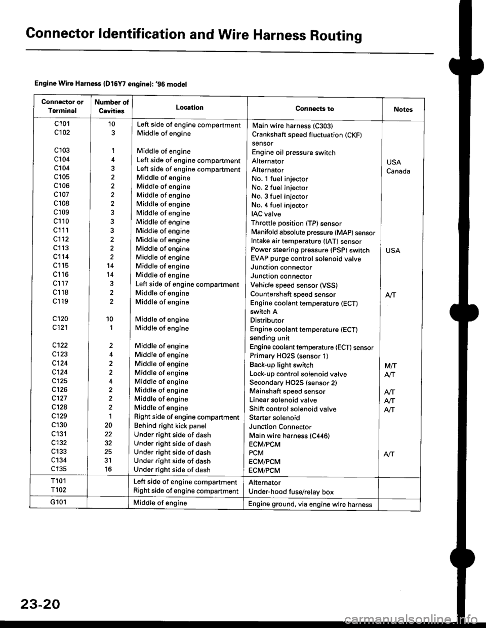
Engine Wire Harness {D16Y7 engine}: '96 model
Conneclor or
Terminal
Number ot
CavhiesLocationConnects toNotes
c101
c102
c 103
c104
c104
c105
c'r06
c107
c 108
c 109
c110
c111
c112
c l13
c't14
LttS
cl16
cl17
c118
cl19
c120
c121
c123
c124
c124
c125
c126
c't27
c12a
c129
c130
c131
c132
c133
c134
c135
10
1
4
5
'14
14
10
1
,,
2
2
1
22
31
16
No. 1 fuel injector INo. 2 fuel injector
No. 3 fuel injector INo,4 fuel injector
IAC valve l
Throttle position (TP)sensor IManifold absolute pressure (MAP) sensorIntake ai. temperature (lAT) sensor ]Power steering pressure (PSP) switch I USAEVAP purge control solenoid valve IJunction connector
Junction connector IVehicle speed sensor (VSS) |Countershaft speed sensor AlTEngine coolant temperature (ECT) I
Main wire harness (C303)
Crankshaft speed fluctuation (CKF)
sensor
Engine oil pressure switch
Alternator
Alternator
switch A
Distributor
Engine coolant temperature (ECT)
sending unit
Engine coolant temperature lECT) sensor
Primary H02S (sensor 1)
Back-up light switch
Lock-up control solenoid valve
Secondary HO2S (sensor 2)
Mainshaft speed sensor
Linear solenoid valve
Shift control solenoid valve
Staner solenoid
Junction Connector
Main wire harness {C446)ECM/PCM
PCM
ECM/PCM
ECM/PCM
Left side of engine compartment
Middle of engine
Middle of engine
Left side of engine compartment
Left side of engine compartment
Middle of engine
Middle of engine
Middle of engine
Middle of engine
Middle of engine
Middle of engine
Middle of engine
Middle of engine
Middle of engine
Middle of engine
Middle of engine
Middle of engine
Left side of engine compartment
Middle of engine
Middle of engine
Middle of engine
Middle of engine
Middle of engine
Middle of engine
Middle of engine
Middle of engine
Middle of engine
Middle of engine
Middle of engine
Middle of engine
Right side of engine compartment
Behind right kick panel
Under right side of dash
Under right side of dash
Under right side of dash
Under right side of dash
Under right side of dash
USA
Canada
M/T
AtJ
Afi
T101
T102
Left side of engine compartment
Right side of engine compartment
Alternator
Under-hood fuse/relay box
G101Middle of engineEngine ground, via engine wire harness
23-20
Page 1492 of 2189
Connector ldentification and Wire Harness Routing
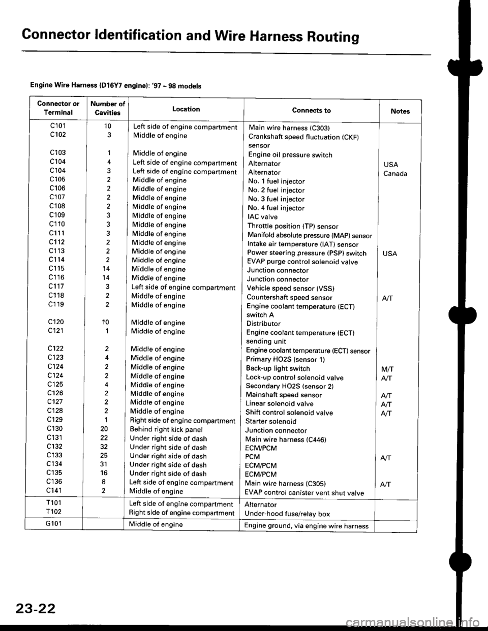
Engine Wire Harness {Dt6Y7 enginel: '97 - 9g models
Connectot or
Terminal
Number of
CsvitiesLocationConnects toNotes
c 101
c102
c103
c104
c104
c105
c106
c107
c 108
c109
cl10
clll
c112
cl13
cl14
c115
c1 l6
c117
c118
cl 19
cl20
c121
c122
c123
cl24
c124
c125
c126
c127
c128
c129
c 130
c 131
c132
c134
c135
cl41
10
1
2
10
I
2
2'>
4
t
20
3r
2
No. l fuel injector
No.2 fuel injector
No. 3 fuel injector INo. 4 fuel injector
IAC valve ]Throttle position (TP) sensor IManifold absolute pressure (MAP) sensorIntake air temperature (lAT) sensor ]Power steering pressure (PSp) switch I USAEVAP purge control solenoid valve
Junction connector IJunction connector IVehicle speed sensor (VSS)
Countershaft speed sensor I enEngine coolant temperature (ECTI
Main wire harness (C303)
Crankshaft speed fluctuation (CKF)
sensor
Engine oil pressure switch
Alte|'nator
Alternator
switch A
Distributor
Engine coolant temperature (ECT)
sending unit
Engine coolant temperature (ECT) sensor
Primary HO2S (sensor 1)
Back-up light switch
Lock-up control solenoid valve
Secondary H02S (sensor 2)
Mainshaft speed sensor
Linear solenoid valve
Shift control solenoid valve
Staner solenoid
Junction connector
Main wire harness (C446)
Left side of engine compartment
Middle of engine
Middle of engine
Left side of engine compartment
Left side of engine compartment
Middle of engine
Middle of engine
Middle of engine
Middle of engine
Middle of engine
Middle of engine
Middle of engine
Middle of engine
Middle of engine
Middle of engine
Middle of engine
Middle of engine
Left side of engine compartment
Middle of engine
Middle of engine
Middle of engine
Middle of engine
Middle of engine
Middle of engine
Middle of engine
Middle of engine
Middle of engine
Middle of engine
Middle of engine
Middle of engine
Right side of engine compartment
Behind right kick panel
Under right side of dash
Under right side of dash
Under right side of dash
Under right side of dash
Under right side of dash
Left side of engine compartment
Middle of engine
USA
Canada
Mtr
AIT
ECM/PCM
PcM I ArrECM/PCM
ECM/PCM
Main wire harness {C305) | AftEVAP control canister vent shut valve
T 101
r102
Left side of engine compartment
Right side of engine companment
Alternator
Under-hood fuse/relay box
G 101Middle of engineEngine ground, via engine wire harness
23-22
Page 1494 of 2189
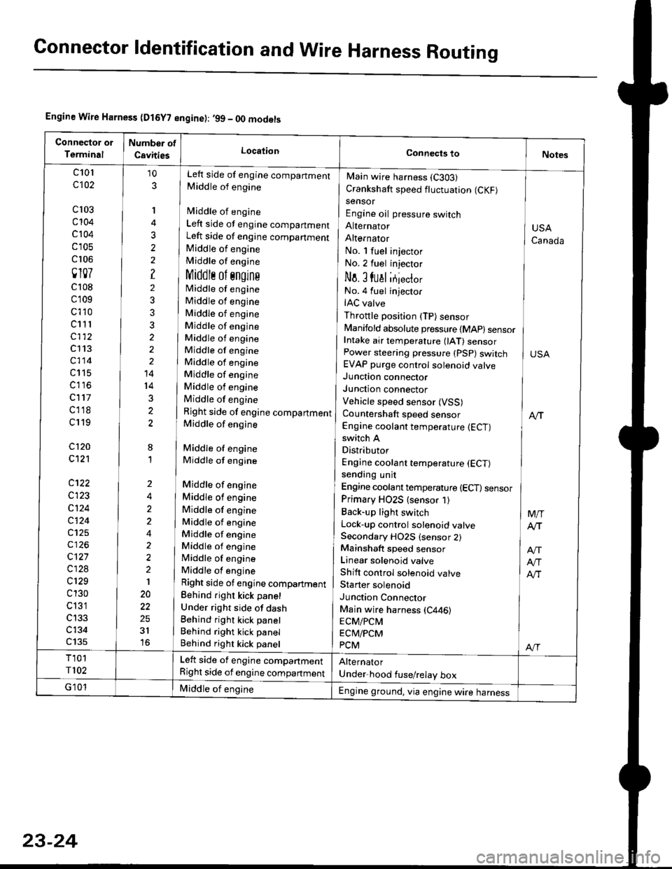
Connector ldentification and WireHarness Routing
Engine Wire Harness (D15Y? engine): ,99 - OO models
c101
c102
cl03
c't04
c 104
c 105
cr 06
0107
c108
c109
c't 10
c11 r
c112
c113
c114
c115
c116
c117
cl18
c119
c120
c121
c122
c123
c124
c124
c125
c127
c128
c129
c 130
c 131
c134
c135
10
3
'I
3
?
2
3?
2
14
14
3
2
8
1
Left side of engine compartment
Middle of engine
fvliddle of engine
Left side of engine compartment
Left side of engine companment
Middle of engine
Middle of engine
Middlr ol sngins
Middle of engine
Middle of engine
Middle of engine
Middle of engine
Middle of engine
Middle of engine
Middle of engine
Middle of engine
Middle of engine
Middle of engine
Right side of engine compartment
Middle of engine
Middle of engine
Middle of engine
Middle of engine
Middle of engine
Middle of engine
Middle of engine
Middle of engine
Middle of engine
Middle of engine
Middle of engine
Right side ot engine compartment
Behind right kick panel
Under right side of dashBehind right kick panel
Behind right kick panel
Behind right kick panel
Main wire harness (C303)
Crankshaft speed fluctuation (CKF)
sensor
Engine oil pressure switch
Alternator
AlternatOr
No. l fuel injector
No.2 fuel injector
No. I fual itjecto,
No.4 fuel injector
IAC valve
Throttle position (TP) sensor
Manifold absolute pressure {MAp) sensorIntake air temperature 0AT) sensorPower steering pressure (PSp) switchEVAP purge control solenoid valveJunction connector
Junction connector
Vehicle speed sensor (VSS)
Countershaft speed sensor
Engine coolant temperature {ECT)switch A
Distributor
Engine coolant temperature (ECT)
sending unit
Engine coolant temperature (ECT) sensor
Primary HO2S (sensor 1)
Back-up light switch
Lock-up control solenoid valveSecondary HO2S (sensor 2)Mainshaft speed sensor
Linear solenoid valve
Shift control solenoid valve
Starter solenoid
Junction Connector
Main wire harness (C446)
ECM/PCM
ECM/PCM
PCM
USA
Canada
M/T
Atr
Atr
Alr
Al-|.
Left side of engine compartment
Right side of engine compartment
Middle of engineEngine ground, via engine wire harness
23-24