relay HONDA CIVIC 2000 6.G Owner's Manual
[x] Cancel search | Manufacturer: HONDA, Model Year: 2000, Model line: CIVIC, Model: HONDA CIVIC 2000 6.GPages: 2189, PDF Size: 69.39 MB
Page 472 of 2189
\
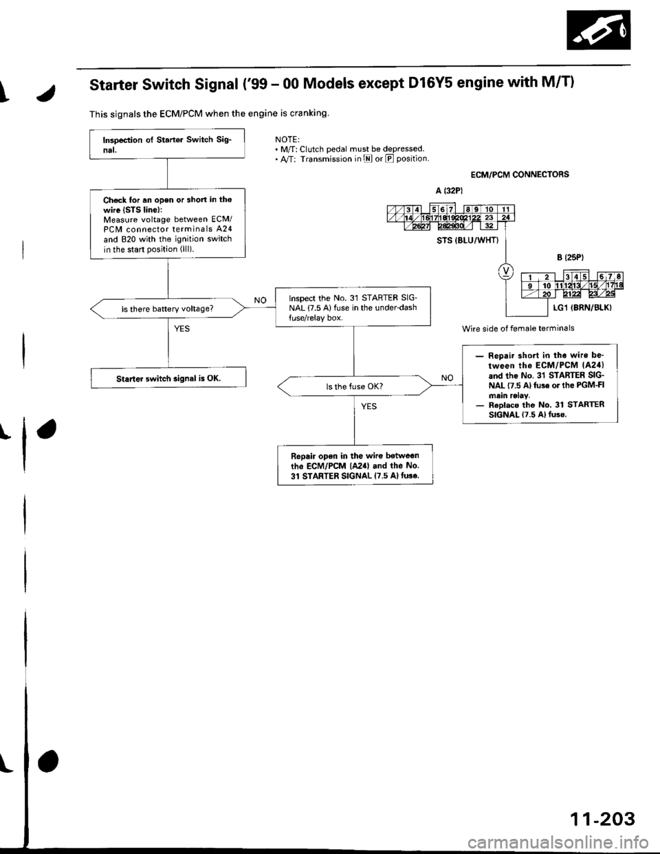
Starter Switch Signal ('99 - 00 Models except Dl6Y5 engine with M/T)
NOTE:. M/f: Clutch pedal must be depressed.. A,/T: Transmission in E or E position
ECM,/PCM CONNECTORS
I
This signals the ECM/PCM when the engine is cranking
Ch€ck for an open or short in the
wire {STS linel:Measure voltage between ECM/PC[/| connector terminals A24
and 820 with the ignition switch
in the start position (lll).
Inspect the No.31 STARTER SIG-NAL (7.5 Alluse in the under-dash
- Repair 3hort in tho wire be'
tween tho ECM/PCM lA24)and tho No. 31 STARTER SIG-NAL 17.5 Al fuse or the PGM-FImein relay.- ReDlaco the No. 31 STARTERSIGNAL 17.5 Al fuse.
Staner 3witch signal is OK.
Repair open in the wirc betwean
the ECM/PCM lA24) and the No.
31 STARTER SIGNAL {7.5 Alfuse.
W;re side of female terminals
Page 474 of 2189
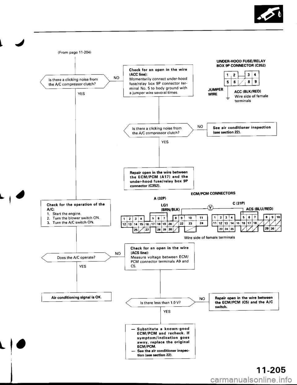
(From page 11-204)
Check for an open in the wir€(ACC linel:Momentarily connect underhood
fuse/relay box 9P connector teF
minal No. 5 to body ground with
a iumper wire several times.
ls there a clicking noise from
the IVC compressor clutch?
See air conditionor inspection(see 3oction 221.ls there a clicking noise from
the Py'C compressor clutch?
Repair open in the wire between
rhe ECM/PCM lAl7l and th6
under-hood fu3e/rolaY box 9P
connector lC352l.
Check for the oPeration of the
Alcl1. Start the engine.2. Turn the blower switch ON
3. Turn the AJC switch ON.
Chock tor an open in the wire
IACS linel:Measure voltage between ECM/
PCM connector terminals A9 and
c5.
Does the Ay'C operate?
Air conditioning signal is OK.Repair open in the wire b€tweenthe EcM/PcM lC5) and the A/c
3witch.ls there less than 1.0 V?
- Substiiute a known-goodECM/PCM and recheck ll
symptom/indication 9oesaway, .oplace the originalECM/PCM.- See the air condhioner insP€c_tion {see s€c{ion 22).
UNDER.HOOD FUSE/BELAYBOX 9P CONNECTOR 1C352)
12Ia
589
ACC (BLK/RI
Wire side ofACC (BLK/REDI
Wire side of female
terminals
JUMPERWIRE
ECM/PCM CONNECTORSrfA t32P)
LGlc {31Pl
t
(BRN/BLK)ACS IBLU/RED)
I23a9101t3I89t0
121315l611la1920232att12't3la't5t617ta
25272A2930232a2930
Wire side of lemale terminals
Page 476 of 2189
I
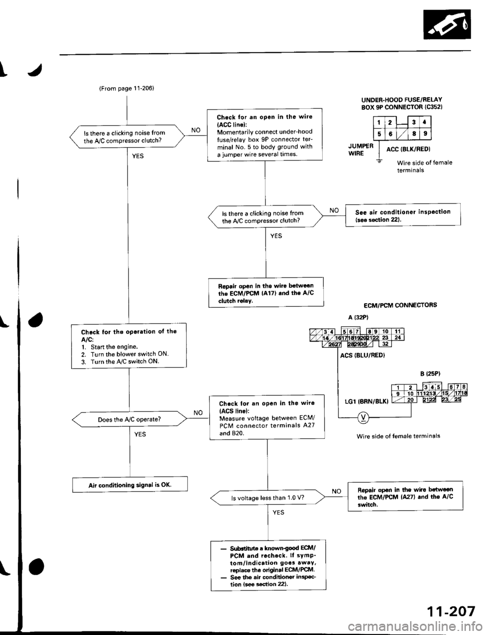
JUMP€RWIRE
UNDER-HOOO FUSE/RELAYsox 9P coNNEcroR lca52l
123a
5689
ACC (8LK/REDI
Wire side ofterminals
ECM/PCM CONNECTORS
A (32P1
female
Wire side of {emale terminals
(From page 11-206)
Check for an open in the wite
IACC lino):Momentarily connect under_hood
luse/relay box 9P connector teF
minal No. 5 to body ground with
a jumper wire several times.
ls there a clicking noise from
the Iy'C compressor clutch?
S6e air conditioner insPoction
l3oa section 221ls there a clicking noise lrom
the ly'C compressor clutch?
Ropair open in tho wilo betwg€n
the ECM/PCM lA17) and the A/C
clutch rolay.
Chock for the oporation of lho
AIC:1, Start the engine.
2. Turn the blower switch ON
3. Turn the ray'C switch ON.
Check lor an open in the wiro(ACS lino):Measure voltage between ECM/
PCM connector terminals A27
and 820.
Does the Iy'C operate?
Air conditioning signal is OK.Repair op6n in the wiro bctwoon
lhe ECM/PCM lA27l and tho A/C
3witch.ls voltage lessthan 1.0 V?
- Sub6iitut€ r known€ood ECtt /PCM and rccheck. ll sYmP-
tom/indication 9oe3.waY,replaca the original ECM/PCM- See the ai. condhionGr in3p€c-tion lsee soc{ion 221.
11-207
Page 479 of 2189
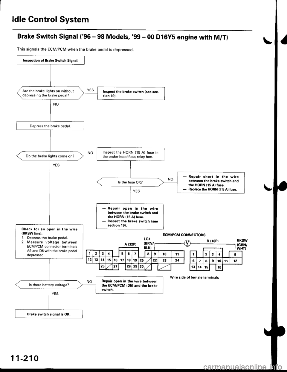
ldle Control System
Brake Switch Signal ('96 - 98 Models, '99 - 00 Dl6YS engine with M/Tl
This signals the ECM/PCM when the brake pedal is deoressed.
LGlBKSW(GRN/WHTI
D {16P)
Wire side of female t€rminals
Inspection of Brake Switch Signal.
Are the brake lights on withoutdepressing the brake pedal?
Depress the brake pedal.
Inspect the HORN (15 A) fuse inthe under-hood fuse/ relay box.Do the brake lights come on?
- Repair short in the wirebetween the brake 3whch andrhe HORN 115 At lu3e.- Replace the I|oRN 17.5 A) tus€.
Repair open in the wirebetween the brake switch andthe HORN 115 Al fuse.Inspect th6 br.ke switch {s6€section l9l.Check tor an open in the wireIBKSW line):1. Oepress the brake pedal.2. Measure voltage betweenECM/PCNI connector terminalsAg and D5 with the brake pedaloepresseo.
Repair open in the wire b€tweenthe ECM/PCM {Dsl and the brakeswitch.
ls there battery voltage?
Brakc switch sign.l is OK.
ECM/PCM CONNECTOFS
A (32PtIBRI\v
,la678101112I
121311151617t8192022232aI9101112
25212Aa3013141516
11-210
Page 480 of 2189
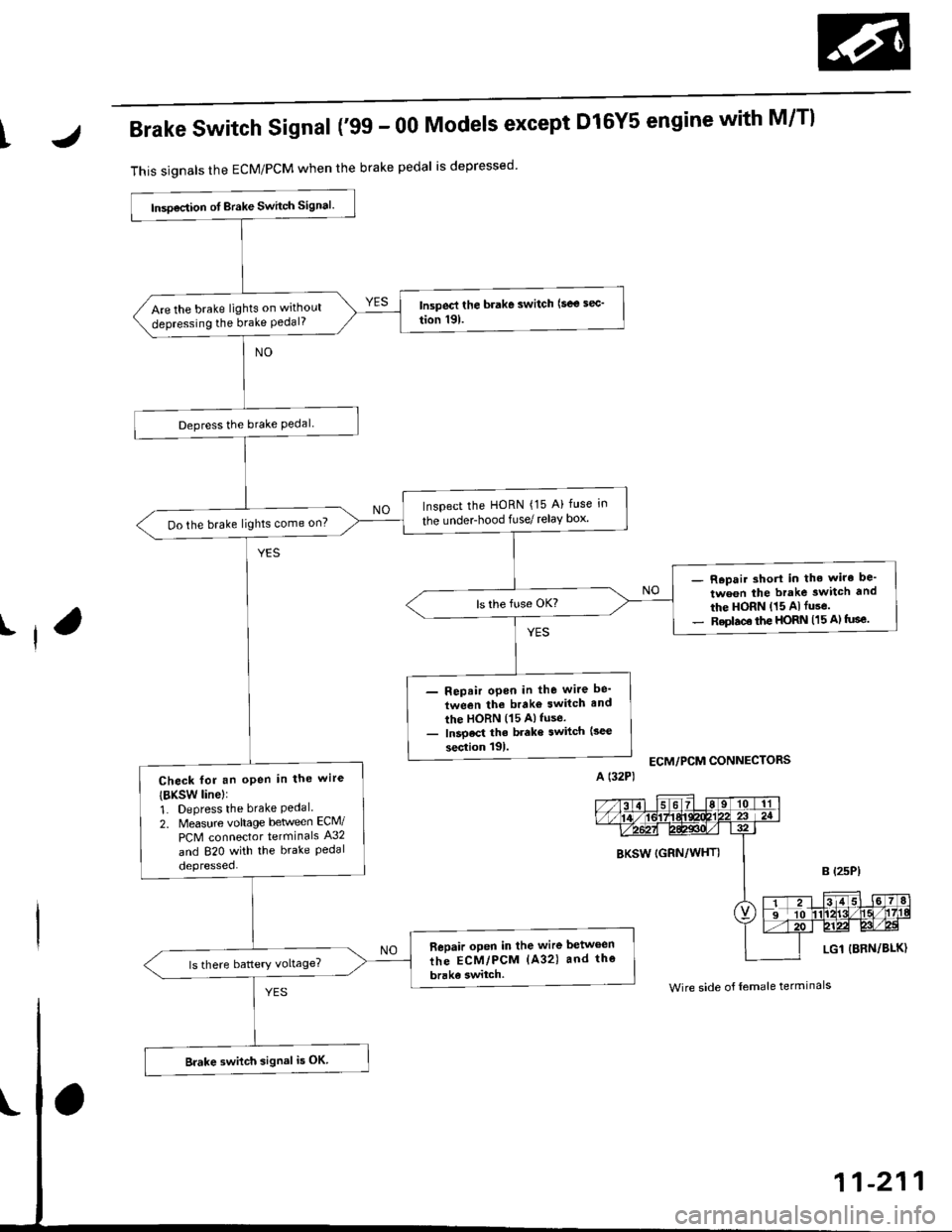
IJBrake Switch Signal ('99 - 00 Models except Dl6Y5 engine with M/Tl
This signals the ECM/PCM when the brake pedal is depressed
I
lnsoection ot Brake Switch signal.
Are the brake lights on without
depressing the brake Pedal?
Depress the brake Pedal
Inspect the HoRN {15 A} fuse in
the underhood fuse/ relay box'Do the brake lights come on?
- R.pair short in the wiro be'
tween the brake switch and
the HORN (15 Alfuse.- Replac€ the HORN (15 A) tuse.
- Repair open in the wite be'
tween the brako switch and
the HORN (15 Alfuse.- lnsoect the brake switch (3ec
section tgl.
Check fot an oPen in the wire
{BKsw linel:
1. Depress the brake Pedal.2. Measure vohage beween ECM/
PCM connector terminals A32
and 820 with the brake Pedaldepressed.
Bepair open in the wire between
the ECM/PCM (A32) and the
brake switch.
Brake switch signal i5 OK
ECM/PCM CONNECTORS
BKSW (GRN/WHTI
LG1 {BRN/BLK)
Wire side o{ female terminals
Page 499 of 2189
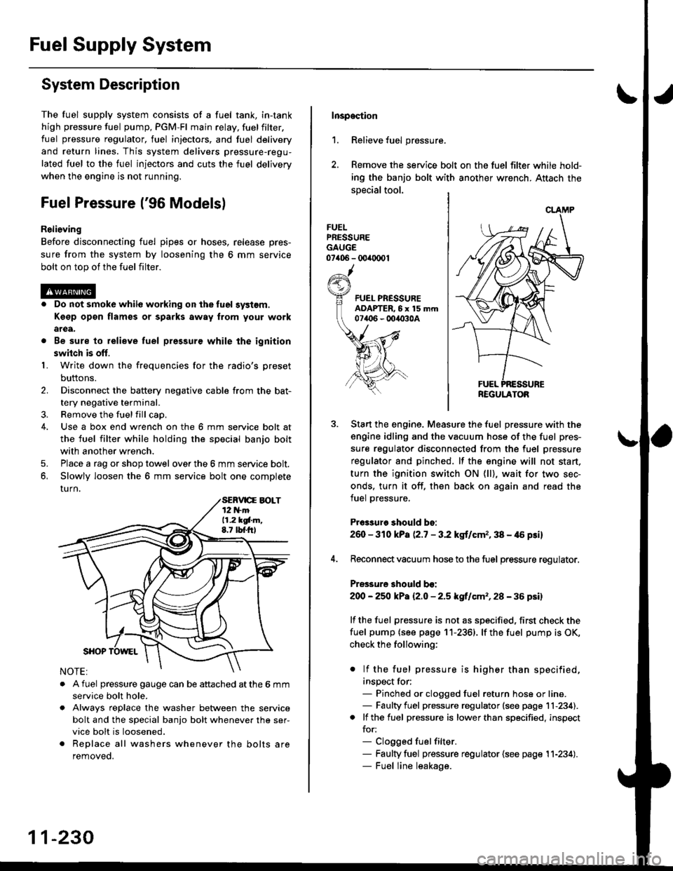
Fuel Supply System
System Description
The fuel supply system consists of a fuel tank, in-tank
high pressure fuel pump, PGM-FI main relay, fuelfilter,
fuel pressure regulator, fuel injectors. and fuel delivery
and return lines. This system delivers pressure-regu-
lated fuel to the fuel injectors and cuts the fuel delivery
when the engine is not running.
Fuel Pressure l'96 Modelsl
Relieving
Before disconnecting fuel pipes or hoses, release pres-
sure from the system by loosening the 6 mm service
bolt on top of the fuel filter.
. Do not smoke whil6 working on the fuel system.
Kgsp opon flames or sparks away from youl work
area.
. Be sure to relieve fuel pressure while the ignition
switch is off.
1. Write down the frequencies for the radio's preset
buttons.
2. Disconnect the battery negative cable from the bat-
tery negative terminal.
3. Remove the fuelfill cap,
4. Use a box end wrench on the 6 mm service bolt at
the fuel filter while holding the special banjo bolt
with another wrench,
5. Place a rag or shop towel over the 6 mm service bolt.
6, Slowly loosen the 6 mm service bolt one complete
rurn.
. A fuel pressure gauge can be attached at the 6 mm
service bolt hole.
. Always reDlace the washer between the service
bolt and the special banjo bolt whenever the ser-
vice bolt is loosened.
. Replace all washers whenever the bolts are
removeo.
11-230
Inspoction
1. Relieve fuel pressure.
2. Remove the service bolt on the fuel filter while hold-
ing the banjo bolt with another wrench. Attach the
special tool.
FUELPRESSUREGAUGE07406 - 00ir0(x)1
Start the engine. Measure the fuel pressure with the
engine idling and the vacuum hose of the fuel pres-
sure regulator disconnected from the fuel pressure
regulator and pinched. lf the engine will not start,
turn the ignition switch ON (ll), wait for two sec-
onds, turn it off, then back on again and read the
fuel pressure.
Pr€3sure should bo:
260 - 310 kPa (2.7 - 3.2 kgt/cmr, 38 - 46 psi)
Reconnect vacuum hose to the fuel pressure regulator,
Pressure should bo:
200 - 25O kPa l2.O - 2.5 kgf/cm'�, 28 - 36 psil
lf the fuel pressure is not as specified, first check the
fuel pump {see page 11-2361. lf the fuel pump is OK,
check the following:
. lf the fuel pressure is higher than specified,
inspect for;- Pinched or clogged fuel return hose or line.- Faulty fuel pressure regulator (see page 11-234).. lf the fuel pressure is lower than specified, inspect
for:- Clogged fuelfilter.- Faulty fuel pressure regulator {see page 11-234).- Fuel line leakage.
REGULATOB
Page 505 of 2189
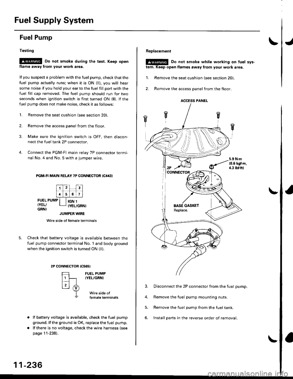
Fuel Supply System
Fuel Pump
Testing
!@ Do not smoke during the test, Keep open
flame away from your work atea,
lf you suspect a problem with the fuel pump, check that the
fuel pump actually runs; when it is ON (ll), you will hear
some noise if you hold your ear to the fuel fill port with the
fuel fill cap removed. The fuel pump should run for two
seconds when ignition switch is first turned ON (ll). lf the
fuel pump does not make noise, check it as follows:
L Remove the seat cushion {see section 20).
2. Remove the access panel from the floor.
3. Make sure the ignition switch is OFF, then discon-
nect the Iueltank 2P connector.
4. Connect the PGM-FI main relay 7P connector termi-
nal No. 4 and No. 5 with a jumper wire.
PGM-R MAIN RELAY 7P CONNECTOR lC4,(|l
FUEL PUMP
IYEL/GRN}
IGN 1(YEL/GRNI
tcs6s)
FUEL PUMP(YEL/GRNI
Wire side oftemale torminals
JUMPER WIRE
Wire side of temale terminals
Check that battery voltage is available between the
fuel pump connector terminal No. 1 and body ground
when the ignition switch is turned ON (ll).
CONNECTOR
=
[t
L3l .i)
T
lf battery voltage is available, check the fuel pump
ground. lf the ground is OK, replace the fuel pump.
lf there is no voltage, check the wire harness (see
page 11-238).
11-236
Replacement
@E Do not smoke while working on tuel svs-
tem. Keep open llames away from your work area.
1. Remove the seat cushion (see section 20).
2. Remove the access panel trom the floor.
3. Disconnect the 2P connector from the fuel pump.
4. Remove the fuel pump mounting nuts.
5. Remove the fuel pump from the fuel tank.
6. Install pans in the reverse order of removal.
ACCESS PANEL
i
Page 506 of 2189
I
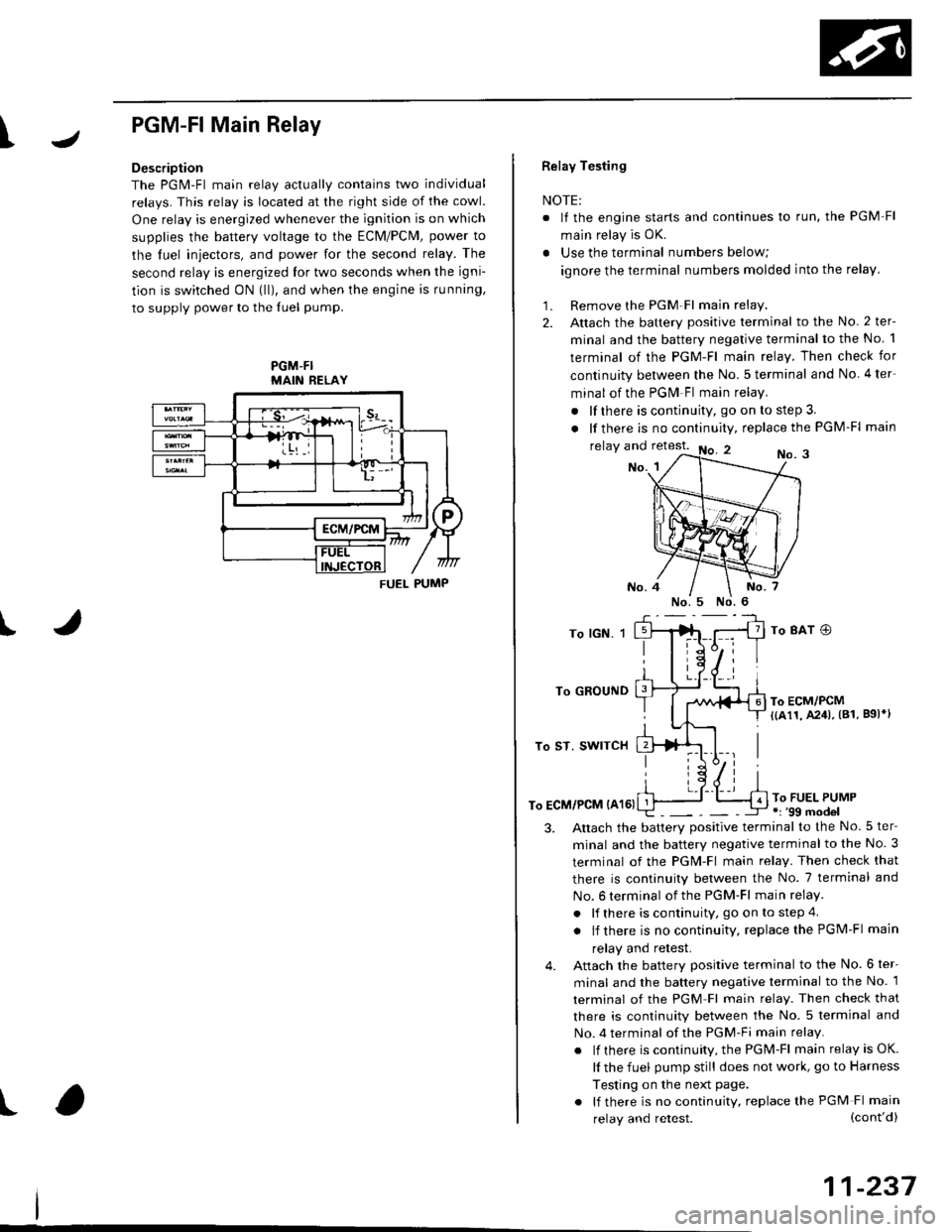
PGM-FlMain Relay
Description
The PGM-Fl main relav actuallv contains two individual
relays. This relay is located at the right side of the cowl.
One relay is energized whenever the ignition is on which
supplies the battery voltage to the ECM/PCM, power to
the luel iniectors, and power for the second relay. The
second relay is energized lor two seconds when the igni-
tion is switched ON (lll, and when the engine is running,
to supply power to the luel pump.
PGM-FIMAIN RELAY
J
I
t
FUEL PUMP
Relay Testing
NOTE:
. It the engine starts and continues lo run. the PGM Fl
main relay is OK.
. Use the terminal numbers below;
ignore the terminal numbers molded into the relay,
1. Remove the PGM Fl main relay.
2. Attach the battery positive terminal to the No. 2 ter-
minal and the battery negative terminal to the No 1
terminal of the PGM-Fl main relay. Then check for
continuity between the No.5 terminal and No 4ter-
minal of the PGM Fl main relay.
. lf there is continuity, go on to step 3.
. lf there is nocontinuity, replacethe PGM-Fl main
relay and retest.No. 3No. 1
To lGN. 1
To GROUND
To ST. SWITCH
To ECM/PCM {A161
To 8AT O
To ECM/PCM{(a11, A241, (81. B9l*l
To FUEL PUMP.r '99 model
3.Altach the batterv positive terminal to the No.5 ter-
minal and the battery negative terminal to the No. 3
terminal of the PGM-Fl main relay. Then check that
there is continuity between the No. 7 terminal and
No. 6 terminal of the PGM-Fl main relay.
. lf there is continuity, go on to step 4
. lf there is nocontinuity, replacethePGM-Fl main
relay and retest.
Attach the battery positive terminal to the No. 6 ter-
minal and the battery negative terminal to the No. 1
terminal of the PGM Fl main relay. Then check that
there is continuity between the No. 5 terminal and
No. 4 terminal of the PGM-Fi main relay.
. lf there is continuity, the PGM-Fl main relay is OK.
lf the fuel pump still does not work, go to Harness
Testing on the next page.
. lf there is no continuity, replace the PGM Fl main
4.
(cont'd)
11-237
relay and retest.
Page 507 of 2189
Fuel Supply System
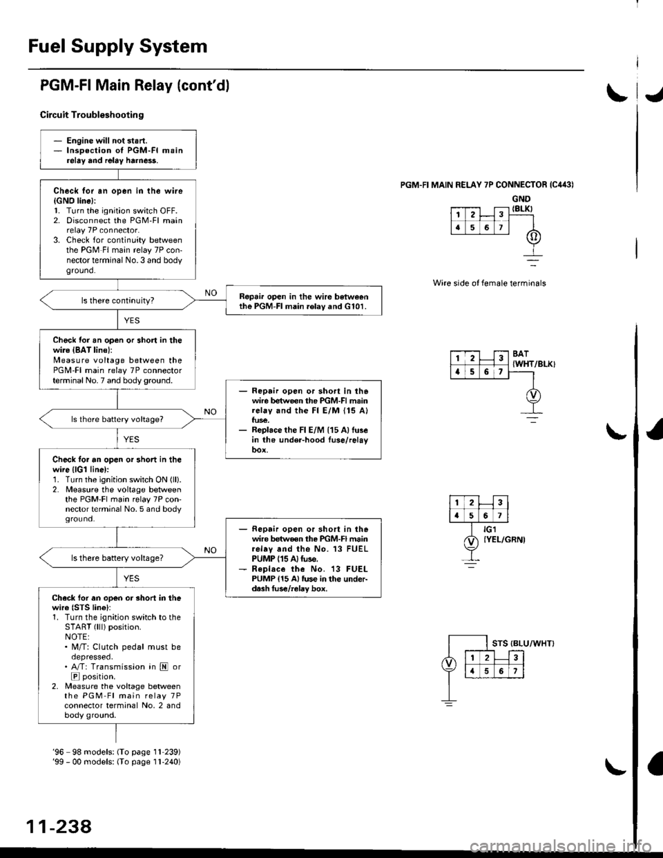
PGM-FI Main Relay (cont'dl
Circuit Troubleshootin g
PGM.FI MAIN RELAY 7P CONNECTOR {C443)
GND{8LK)
Wire side of female terminals
/BLK}
- Engine will not start.- lnsoection of PGM-FI mainrelay and relay harne$.
Check for an open in the wire{GNO line}:l. Turn the ignition switch OFF.2. Disconnect the PGM-Fl mainrelay 7P connector.3. Check for continuity betweenthe PGM Fl main relay 7P con-nector terminal No.3 and bodyground.
Ropai. open in the wir€ betweenthe PGM-FI main .elav and G101.
Check for an open or short in thewire {BAT lin€}:N4easure voltage between thePGM-FI main relay 7P connectorterminal No. 7 and body ground.- Repair open or sho.t in thewire between the PGM-FI mainrelay and the Fl E/M {15 A}fus€.- Replace the Fl E/M (15 Allu3ein the under-hood fuse/relayoox.
ls lhere battery voltage?
Check tor an open or short in thewire {lGl line):1. Turn the ignition switch ON (ll).
2. Measure the voltage betweenthe PGM-Fl main relay 7P con'nector terminal No. 5 and bodyground.- Repair open or short in thewire betwoen the PGM-FI mainrelav and the No. 13 FUELPUMP (15 A)tuse.- R€place the No. 13 FUELPUMP {15 A} tus€ in the under-d.sh fus€/relay box.
ls there battery voltage?
Ch.ck for an open or short in thewire {STS lino}r1. Turn the ignition switch to theSTART (lll) position.NOTE:. M/T: Clutch pedal must beoepresseo.. A/T: Transmission in E or
E position.2, Measure the voltage betweenthe PGM-Fl main relay 7Pconnector terminal No, 2 andbody ground.
12
[,a567
123BAT
{WHTa56,
'96 98 models: (To page 1l 239)'99 - 00 models: (To page I l-240)
11-238,
Page 508 of 2189
JI
I
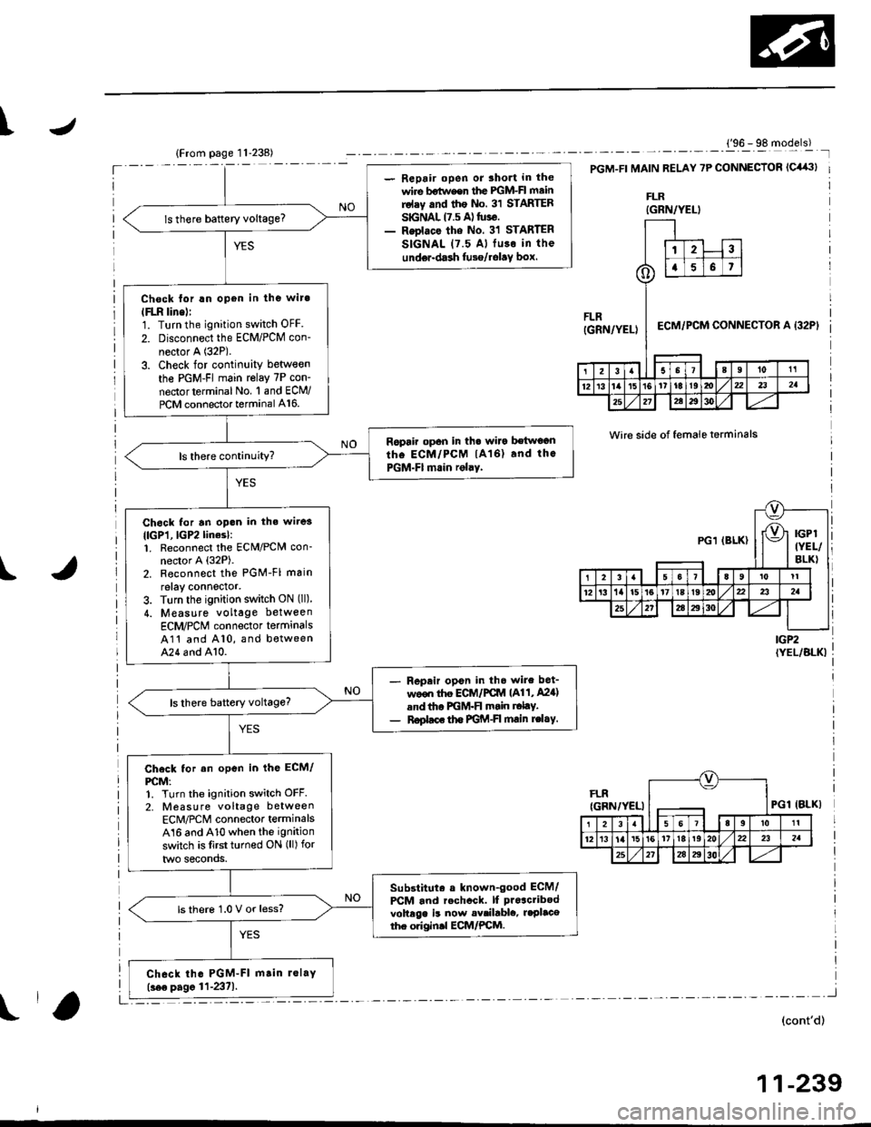
- Repair open or 3hort in the
wire bstw€er the lGM-Fl mainrolsy .nd the No. 31 STARTERSGNAL 17.5 A) tuse.- Reolace the No. 31 STARTER
SIGNAL (7.5 Al fu3o in the
unde.-dash tusg/rolav box.
ls there baftery voltage?
Chock lor !n open in the wit.
lFLn line)l1. Turn the ignition switch OFF
2. Disconnect the ECM/PCM con-
nector A (32P).
3. Check for continuity between
the PGM-FI main relay 7P con-
nectorterminal No. 1 and ECM/
PCM connector terminal A16.
Ropair op6n in th. walo betwoanthe ECM/PCM lA16) and thc
PGM-FI main rolaY.
Ch6ck for an opon in th. wi.e3
llcPl,lGP2linesl:1. Reconnect the ECM/PCN4 con-nector A (32P).
2. Reconnoct the PGM-Fl main
relay connector,3. Turn the ignition switch ON (ll)
4. Measure voltage between
ECM/PCM connector termanals
A11 and A10, and betweenA24 6nd A10.
Repeir opon in th6 wire bet-
ween ttre ECiA /PCM (A11, A24)
and tho PGM-FI msin r.lty.
R€plac. tho FGM-FI main rc|.Y.
Check tor an open in the ECM/
PCM:1. Turn the ignition switch OFF.
2, Measure voltage between
ECM/PCM connector terminalsA16 and A10 when the ignition
switch is lirst turned ON (ll) for
two seconds.
Substituta a known-good ECM/
PCM and rechcck. lf proacribod
voltege is now availablc, r.Placethe originll ECM/PCM.
ls thero 1.0 V or less?
Ch6ck th. PGM-FI m.in lolay(.ee pagc 11-2371.
('96 - 98 models)
t32Pt
Wire side of female terminals
IGP2{YEL/BLKI
FLRIGRN/YELIPGl
3l5 6 7l lslel tl1l
1213'tal5t6't7t8t920221 232a
2527284t
(cont'd)
1 1-239
IBLK)
{GRN/YELI
FLR(GRN/YELI
23
()a6t
ECM/PCM CONNECTOR A
21Il0t1
12r31'al5't61'tti9ml,/x2232a
25212e293ol./
PGl (BLK)
1I
12't/t15t617t8t9zi
25272A4t304l