Switch HONDA CIVIC 2000 6.G Workshop Manual
[x] Cancel search | Manufacturer: HONDA, Model Year: 2000, Model line: CIVIC, Model: HONDA CIVIC 2000 6.GPages: 2189, PDF Size: 69.39 MB
Page 1409 of 2189
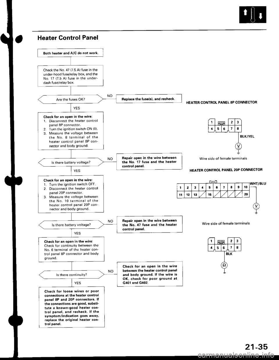
Both heater and A/C do nol work.
checkthe No.47 (7.5 A)fuse in the
under-hood fuse/relay box, and theNo. 17 {7.5 A) fuse in the under-
dash fuse/relay box.
ReDlace the tuse{s), and recheck.
Check lor an open in the wire:
1. Disconnect the heater controlpanel 8P connector,2. Turn the ignition switch ON (ll).
3. Measure the voltage between
the No. I terminal of the
heater control panel 8P con-
nector and body ground.
Repair open in the wire betweenthe No. '17 luse and th6 heatercontrol oanel,ls there battery voltage?
Check for an open in the wire:
1. Turn the ignition switch OFF.
2. Disconnect the heater controlpanel20P connector.3. Measure the voltage lletweenthe No. 10 terminal of theheater control Panel 20P con-nector and body ground.
Repair op6n in the wir€ between
the No. il7 tuse and the heater
controloanel,ls there battery voltage?
Check for an open in the wite:Check for continuity between theNo. 6 terminal of the heater con
trol panel 8P connector and bodyground.
Ch6ck tor an open in lhe wire
betwoen the heator control Paneland bodv ground. lf the wire isOK, check for poor ground atG401 and G402.
ls there continuity?
Check for looso wires or Poolconneciions at the heater controloanel 8P and 20P connectors. lf
the connections are good, substi'
tute a known-good heat€r con-trol Danel, and recheck. lI thesymptom/indication goes awaY,r6place the original h€ater con-troloanel.
HEATER CONTROL PANEL 8P CONNECTOR
BLK/YEL
Wire side of female terminals
HEATER CONTROL PANEL 2OP CONNECTOR
Wire side of temale terminals
I2
1578
BLK
o
1
4I
v
Page 1410 of 2189
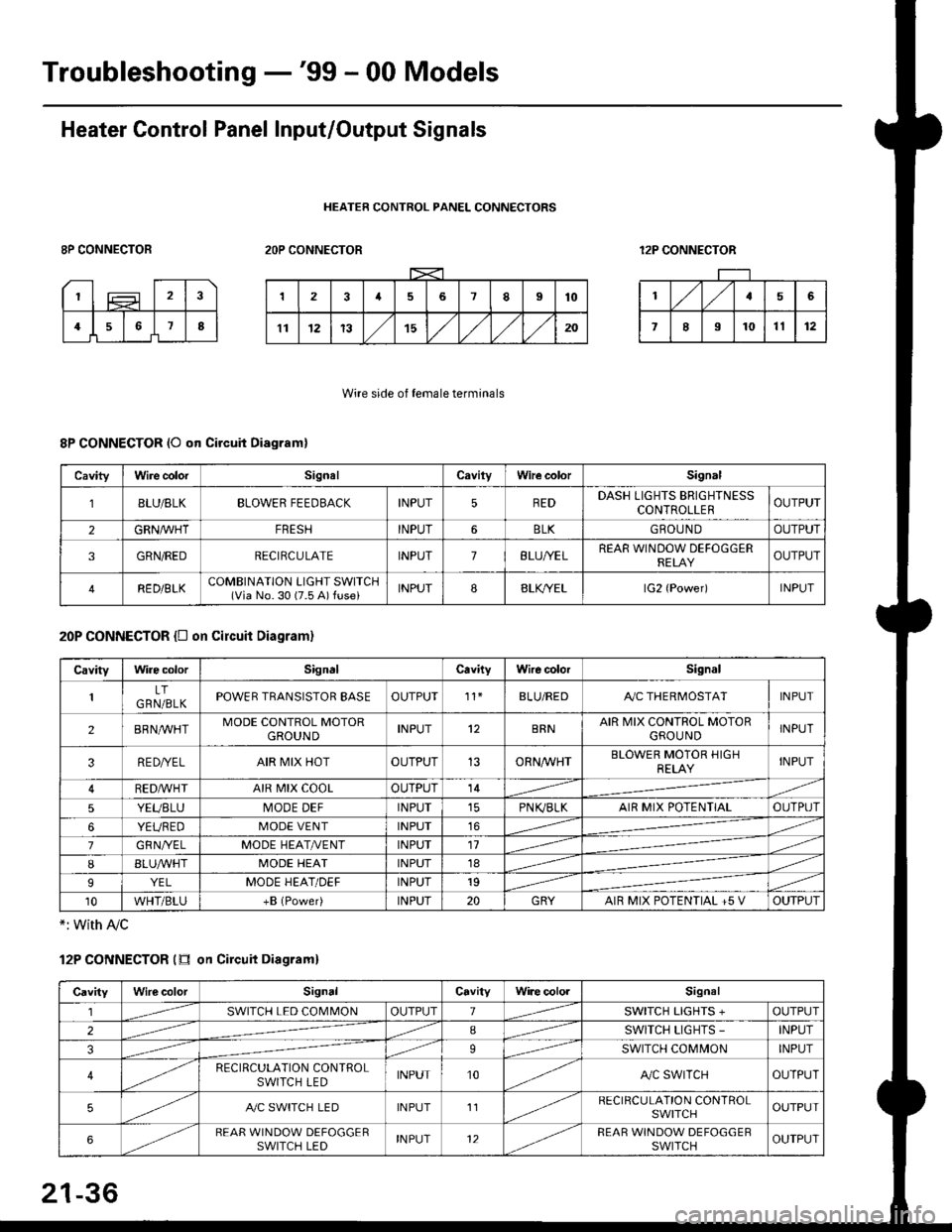
Troubleshooting -'99 - 00 Models
Heater Control Panel Input/Output Signals
HEATER CONTROL PANEL CONNECTORS
8P CONNECTOR2OP CONNECTOR12P CONNECTOR
Wire side of female terminals
8P CONNECTOR (O qn Circuit Diagram)
20P CONNECTOR {D on circuit Diagram}
*: with Ay'c
12P CONNECTOR (tr on Circuit Diagraml
CavityWire colorSignalCavilyWhe colorSignal
BLU/8LKBLOWER FEEDBACKINPUT5REDDASH LIGHTS BRIGHTNESSCONTROLLEROUTPUT
2GRN/lVHTFRESHINPUT6BLKGBOU N DOUTPUT
3GRN/REDRECIRCULATEINPUT7BLU/YELREAR WINDOW DEFOGGERRELAYOUTPUT
4RED/BLKCOMBINATION LIGHT SWITCH(Via No. 30 (7.5 A) fuse)INPUT88LfiELlG2 {Power)INPUT
CavityWire colorSignalCavityWire colorSignal
LTGRN/BLKPOWER TRANSISTOR EASEOUTPUT't1BLU/REDAy'C THERMOSTATINPUT
2BRNMHTMODE CONTROL MOTORGROUNDINPUT12BRNAIR MIX CONTROL MOTORGROU NDINPUT
3RE D/YELAIR MIX HOTOUTPUT13ORNAA/HTBLOWER MOTOR HIGHRELAYINPUT
RED,ryvHIAIR MIX COOLOUTPUT14
5YEUBLUMODE DEFINPUTPN K,/BLKAIR MIX POTENTIALOUTPUT
6YEUREDMODE VENTINPUT16
7GRNI/ELMODE HEAT/r'ENTINPUT11
IBLUAVHTMODE HEATINPUT18
9YELMODE HEAT/DEFINPUT19
10WHT/BLU+B (Power)INPUT20GRYAIR MIX POTENTIAL +5 VOUTPUT
CavityWilecolorSignalCavityWi.e cololSignal
lSWITCH LED COMMONOUTPUT1SWITCH LIGHTS +OUTPUT
2ISWITCH LIGHTS -INPUT
39SWITCH COMMONINPUT
4RECIRCULATION CONTROLSWITCH LEDINPUT10A,/C SWITCHOUTPUT
5A./C SWITCH LEDINPUT11RECIRCULATION CONTROLSWITCHOUTPUT
6REAR WINDOW DEFOGGERSWITCH LEDINPUT12REAR WINDOW DEFOGGEBSWITCHOUTPUT
21-36
Page 1411 of 2189
Blower Unit
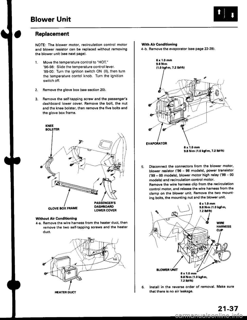
Replacement
NOTE: The blower motor, recirculation control motor
and blower resistor can bs replacsd without rsmoving
th€ blower unit (see neld Page).
1. Move the temperature control to "HOT."
'96-98: Slide the temperature control lever.'99-00: Turn the ignition switch ON (ll), then turn
the temperature contol knob. Turn the ignition
switch off,
Remove the glovs box (ses ssction 20),
R€move ths s6lf-tapping screw and ths passsng6r's
dashboard low€r cover. Removo the bolt, the nut
and the kn€e bolst€r, then remove the fiv€ bolts and
the glove box trame,
Without Air Condhioning
4-a. Remove the wiro harness from the h68t€r duct, then
remove the two self-tapping scrsws and the heatsr
duct.
KNEE
GLOVE BOX FRAME
HEATER DUCT
21-37
Wrth Air Conditioning
4-b. Removo th6 ev8porator (sss pago 22-28).
6x1.0m|n9.8 N'm
6x1.0mm9.8 N'm lt'o tgf'm, t.2 lb{'ttl
Disconnoct the connectors trom th€ blower motor,
blowor r6sistor {'96 - 98 models), power transiator
('99 - 0O modsls), blowor motor high telay ('99 - 00
models) and recirculation control motor.
R€mov€ ths wiro harnoss clip from tho recirculation
control motor, and release the wir6 harnsss from ths
clamo on the blowor unit. Remove the two mount-
ing bolts, tho mounting nut and ths blowor unit'
9.8 .m 11.0 tgfm,1.2 tblfrl
lnstall in ths reverso order of removal. Mako surs
that thsre is no air leaka96.
6x1.0mm9,t N'm 11.0lgi.m,7.2 tbf.fil
Page 1416 of 2189
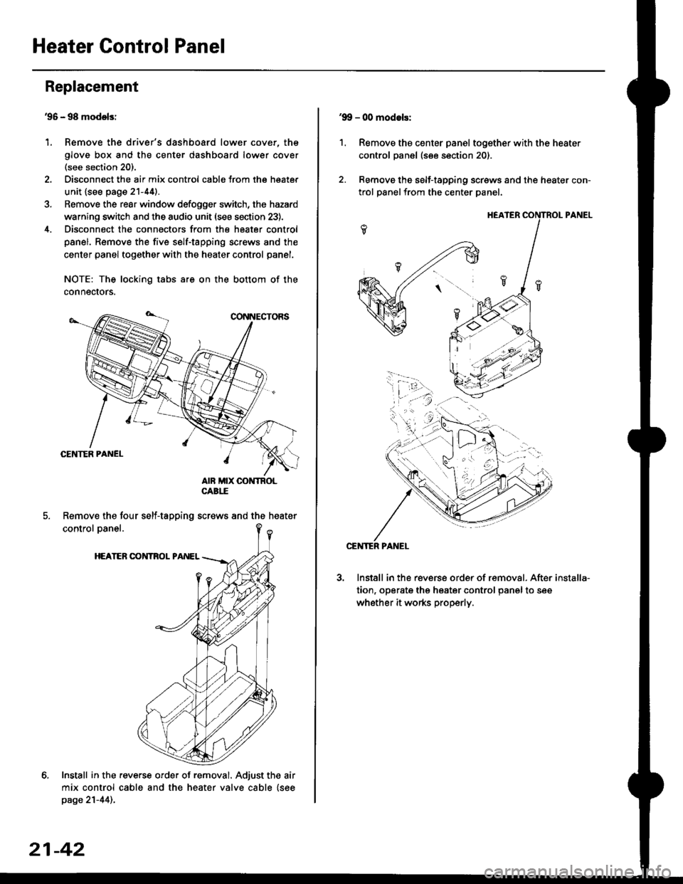
Heater Control Panel
'95 - 98 modolsi
Remove the driver's dashboard lower cover, the
glove box and the center dashboard lower cover(see section 20).
Disconnect the air mix control cabls from the heater
unit {see page 21-44).
Remove the rear window defogger switch, the hazard
warning switch and the audio unit (see section 23).
Disconnect the connectors from the heater control
panel. Remove the five self-tapping screws and the
center panel together with the heater control panel.
NOTE: The locking tabs are on the bottom of the
connecrors.
Install in the .everse order of removal. Adjust the air
mix control cable and the heater valve cable {seepage 21-44)..
Replacement
1.
Remove the four self-tapping screws and the heater
21-42
1.
'9!, - 00 modols:
Remove the center panel together with the heater
control panel (see section 20).
Remove the self-tapping screws and the heater con-
trol panelfrom the center Danel.
Install in the reverse order of removal. After
tion, operate the heater control panel to see
whether it works properly.
installa-
Page 1417 of 2189
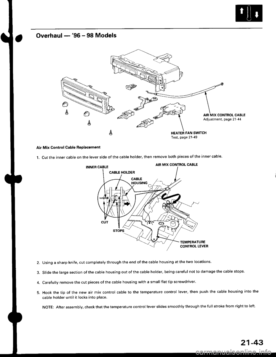
Overhaul -'96 - 98 Models
HEATER FAN SWITCHTest, page 21-49
Air Mix Control Cable Replacomenl
1. Cut the inner cable on the lever side of the cable holder, then remove both pieces of the inner cable.
2. Using a sharp knife, cut completely through the end of the cable housing at the two locations.
3. Slidethe largesection ofthecable housing outofthe cable holder, being careful not to da mage the cable stops.
4. Carefully remove the cut pieces of the cable housing with a small flat tip screwdriver.
5. Hook the tip of the new air mix control cable to the temperature control lever, then push the cable housing into the
cable holder until it locks into place.
NOTE: After assembly, check that the temperature control lever slides smoothly through the full stroke lrom right to left.
21-43
Page 1419 of 2189
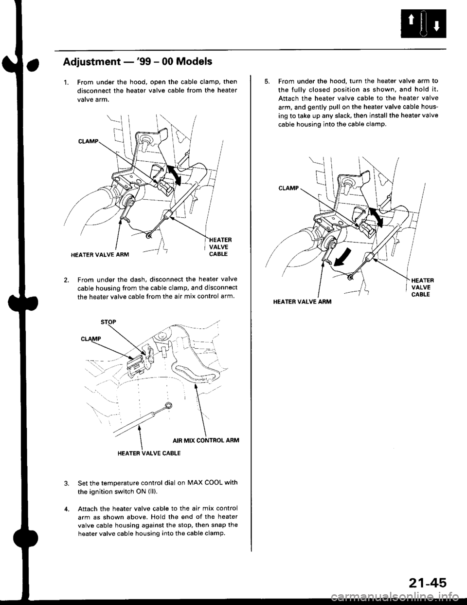
Adjustment -'99 - 00 Models
1. From under the hood, open the cable clamp, then
disconnect the heater valve cable from the heater
valve arm.
From under the dash. disconnect the heater valve
cable housing from the cable clamp, and disconnect
the heater valve cable from the air mix control arm.
HEATER VALVE CABLE
Set the temperature control dial on MAX COOL with
the ignition switch ON {ll).
Attach the heater valve cable to the air mix control
arm as shown above. Hold the end of the heater
valve cable housing against the stop, then snap the
heater valve cable housing into the cable clamp.
HEATER VALVE ARM
5. From under the hood. turn the heater valve arm to
the fullv closed oosition as shown, and hold it,
Attach the heater valve cable to the heater valve
arm, and gently pull on the heater valve cable hous-
ing to take up any slack, then install the heater valve
cable housing into the cable clamp.
HEATER VALVE ARM
21-45
Page 1423 of 2189
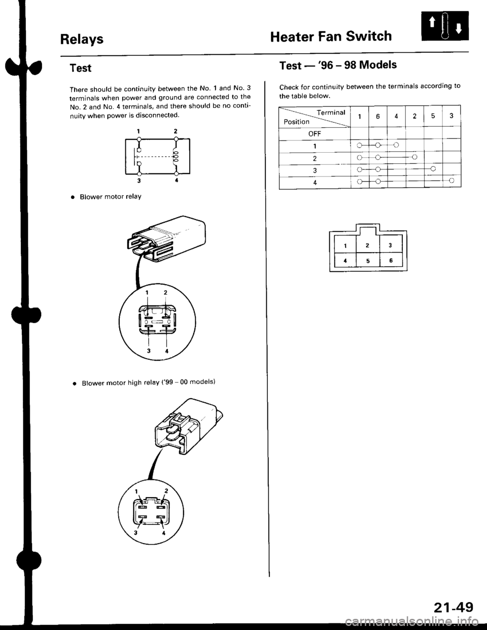
RelaysHeater Fan Switch
Test
There should be continuity between the No 1 and No. 3
terminals when power and ground are connected to the
No.2 and No. 4 terminals, and there should be no conta-
nuity when power is disconnected.
Blower motor relaY
. Blower motor high relay ('99 00 models)
,I It;€'Y )
Test -'96 - 98 Models
Check for continuity between the terminals according to
the table below.
lerminal
Position14253
OFF
1I�rJ
2o-o
3o-a
4c)-{
21-49
Page 1424 of 2189
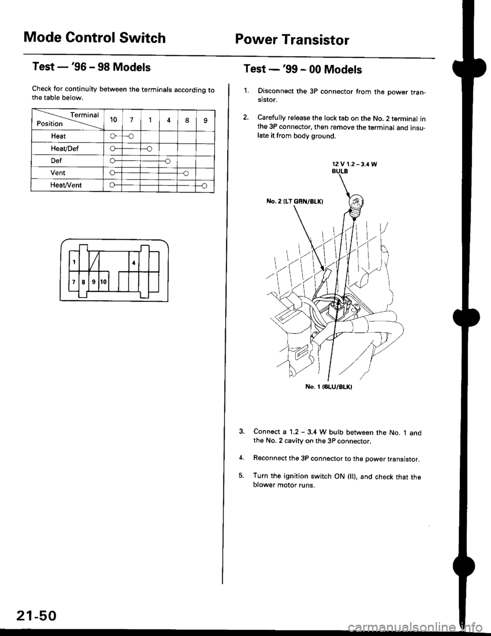
Mode Control SwitchPower Transistor
Test -'96 - 98 Models
Check for continuity between the terminals accordinq tothe table below.
Terminal
Position't071
Heato-o
HeaVDefo---o
Defo--o
VentG-o
HeaVVento--o
1
;l t
4
789
21-50
Test -'99 - 00 Models
1. Disconnsct the 3P connector from the oower tran-stsror.
2, Carefully release the lock tab on the No. 2 terminal inthe 3P connector, then remove the terminal and insu-late it from body glound.
Connect a 1.2 - 3.4 W bulb between the No. 1 andthe No. 2 cavity on the 3P connector.
Reconnect the 3P connector to the power translstor.
Turn the ignition switch ON fll), and check that theblower motor runs.
12V 1.2-3,1W
No. 1 laLU/aLK)
Page 1427 of 2189
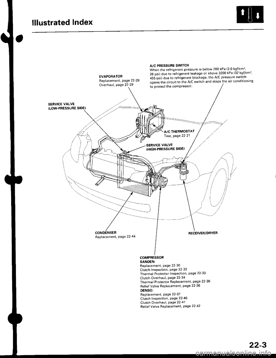
lllustrated Index
A/C PRESSURE SWITCHWhen the refrigerant pressure is below 200 kPa {2 0 kg7cm'�,
28 psi) due to ;frigerant leakage or above 3200 kPa (32 kgf/cm'�'
455 psi) due to refrigerant blockage, the lVC pressure swrtch
SERVICE VALVE
{LOW.PRESSURE SIDE)
EVAPORATORReplacement, page 22-28
Overhaul, page 22 29
Beplacement, Page 22'44
opens lhe circuit to ihe AVC switch and stops the air condilioning
to protect the comPressor'
RECEIVER/DRYER
COMPRESSORSANDENIReplacement, Page 22 30
CIutch Inspection, Page 22 33
Thermal Protector Inspection, page 22 33
Clutch Overhaul, Page 22'34
Thermal Protector Replacement, page 22 36
Refief Vafve Replacemenl, page 22'36
DENSO:Replacement, Page 22-37
Clutch Inspection, Page 22-40
Clutch Overhaul, Page 22_41
Relief Valve Replacement, page 22-42
A/C THERMOSTATTest, page 22 21
22-3
Page 1429 of 2189
Description
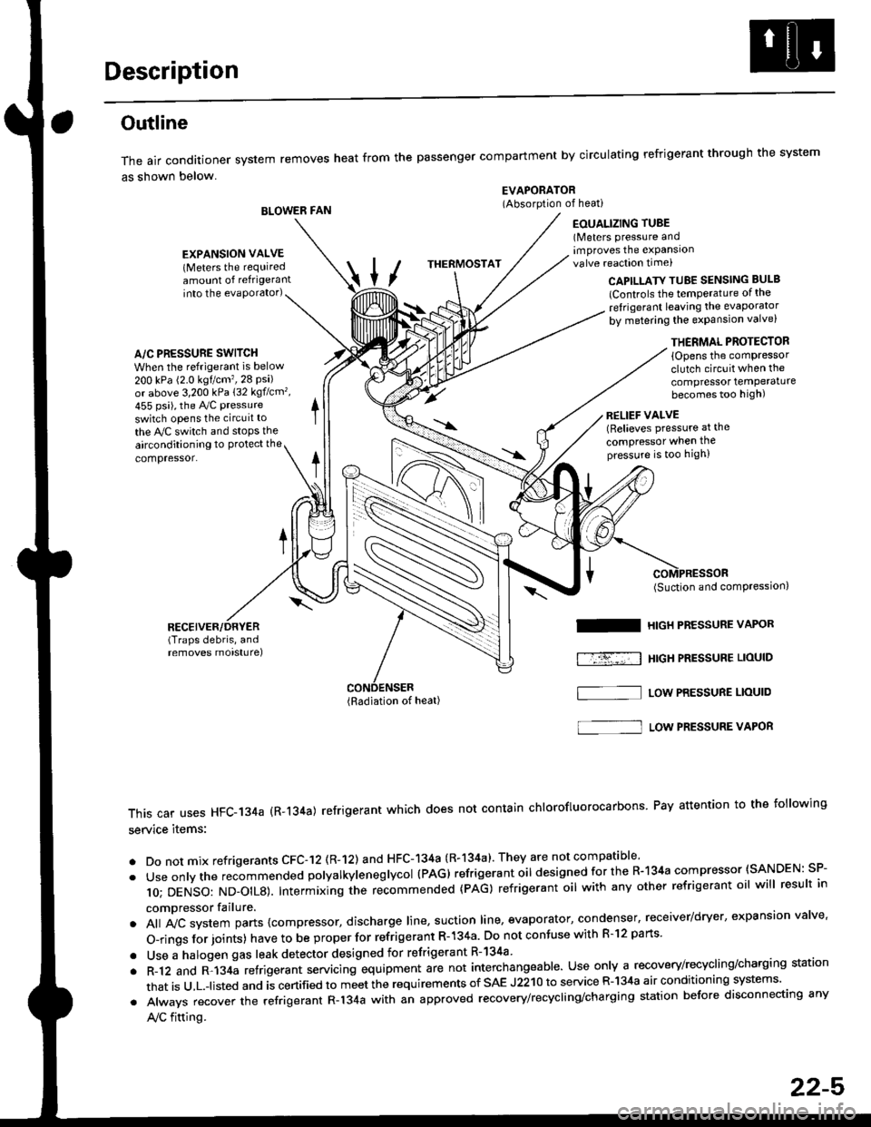
Outline
The air conditioner system removes heat from the passenger compartment by circulating refrigerant through the system
as shown below.
BLOWER FAN
EVAPORATOR(Absorption of heati
EOUALIZING TUBE(Meters pressure andimproves the expansionvalve reaction time)
into the evaporator)CAPILLATY TUBE SENSING BULB
lControls the temPerature of the
ref rigerant leaving the evaporator
by metering the expansion valve)
/\
THERMOSTAT
A/C PRESSURE SWITCH
When the refrigerant is below
200 kPa (2.0 kgtcm'�,28 Psi)or above 3,200 kPa 132 kgflcm',
455 psi), the Ay'C pressure
switch opens the circuit to
the A,/C switch and stops the
EXPANSION VALVE(Meters the requiredamount of refrigerant
airconditioning to Protect the
compressor.
RECEIVER/DRYER(Traps debris, andremoves morsturel
THERMAL PROTECTOR
{Opens the comPressorclutch circuit when the
compressor temPeraturebecomes too high)
RELIEF VALVE(Relieves pressure at the
compressor when thepressure is too high)
(Radiation of heat)
I
f-r-�-; I
(Suction and comPression,
HIGH PRESSURE VAPOR
HtGH PRESSUBE LIOUID
LOW PRESSURE LIOUID
This car uses HFC-134a (R-134a) refrigerant which does not contain chlorofluorocarbons Pay attention to the following
service items:
. Do not mix refrigerants CFC-12 (R-12) and HFC-134a (R-134a)' They are not compatible'
. Useonlythe recommended polyalkyieneglycol (PAG) refrigerant oil designedforthe R-134a compressor (SANDEN: SP-
10; DENSO: ND_OIL8). Intermixing ihe re-commended (pAG) refrigerant oil with any other refrigerant oil will result in
compressor failure.
. All A,,ic system parts {compressor, discharge line, suction line, evaporator, condenser, receiver/dryer, expansion valve'
O-rings for joints) have to be proper for refrigerant R- 134a Do not confuse with R-l2 parts'
. Use a halogen gas leak detector designed for refrigerant R-134a
. R-12 and R-134a refrigerant servacing equipment are not interchangeable. Use only a recovery/recycling/charging station
that is u,L.-listed and is certified to meet the requirements of sAE J2210 to service R-134a air conditioning systems'
. Always recover the refrigerant R-134a with an approved recovery/recycling/charging station before disconnecting any
A,/C fitting.
S]
22-5