Switch ac HONDA CIVIC 2000 6.G Workshop Manual
[x] Cancel search | Manufacturer: HONDA, Model Year: 2000, Model line: CIVIC, Model: HONDA CIVIC 2000 6.GPages: 2189, PDF Size: 69.39 MB
Page 1430 of 2189
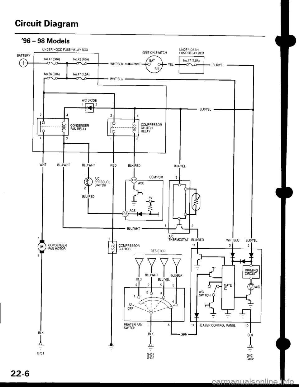
Circuit Diagram
UNDER DASHFUSE/RELAY 8OX
N0.17 (7.54)
'96 - 98 Models
UNDER.HOOD FUSEi BELAY BOX
WHT/SLU BLKYEL
BLK
+
G751
3
'o
I8LK
I
G40lG402
GNITON SWITCH
N0.41 (8rA) N0.42 (40A)
COMPBESSORCLUTCHBELAY
BLUMHT
,l
(E) i,T'
BLUi BED
A/c ITHERMOSTAI BLU/REO
CONDENSEFFAN MOTOR
*F,.X,
FAN rl
BLK
{
G401G402
HEATERswrlcH
32
22-6
Page 1435 of 2189
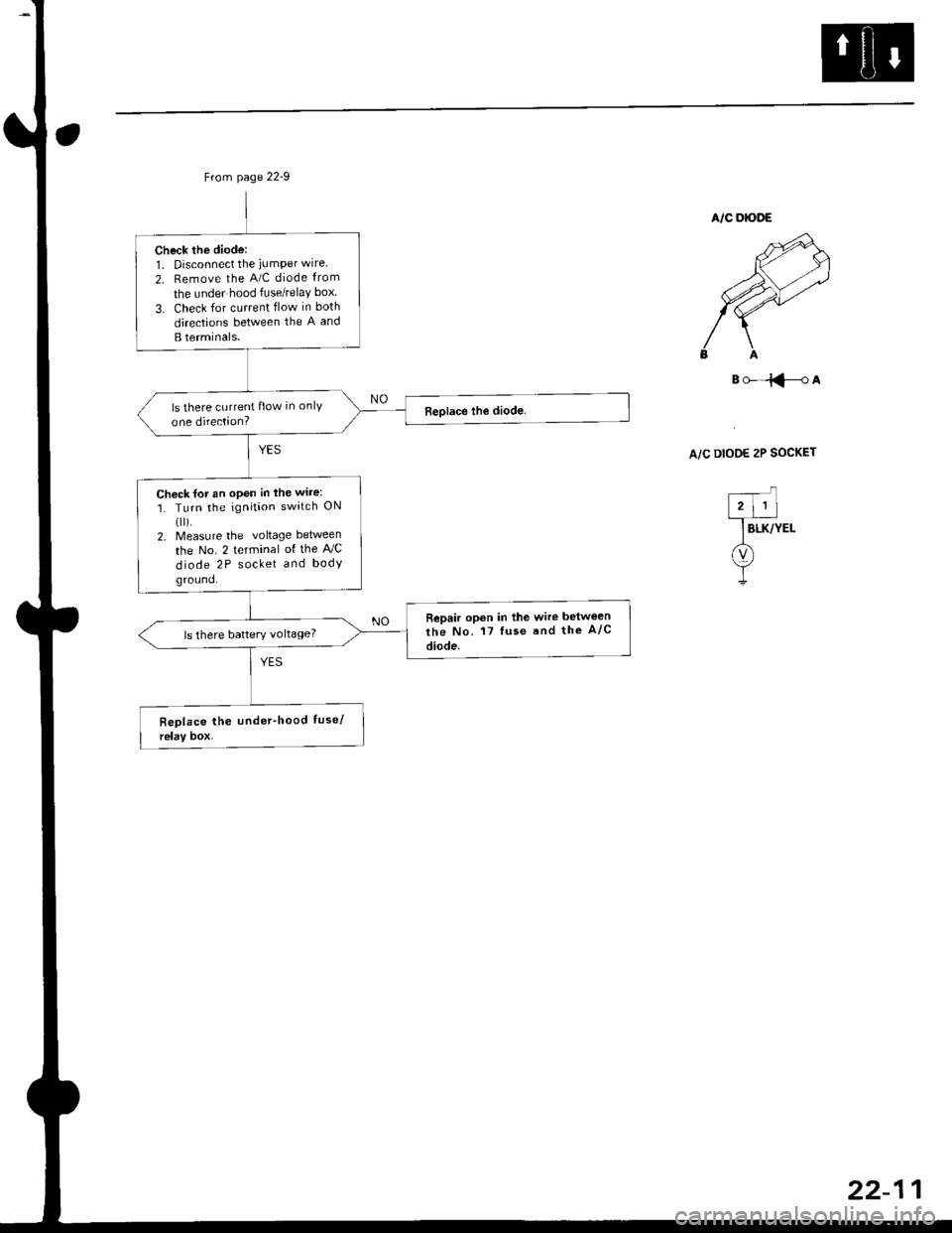
Check the diode:1. Disconnect the iumPer wire
2. Remove the A/C diode from
the under hood fuse/relaY box
3. Check for current flow in both
directions between the A and
B terminals.
ls there current flow in onlY
one direction?
Chock for an open in the wire:
1. Turn the ignition switch ON(ll).
2. Measure the voltage between
the No. 2 terminal of the AJC
diode 2P socket and body
ground.
Repair opon in the wire betwe€n
the No. 17 luse and the A/c
diode.ls there battery voltage?
B()-=iFA
A/C DIOOE 2P SOCKET
Page 1438 of 2189
![HONDA CIVIC 2000 6.G Workshop Manual Troubleshooting
Compressor lcontdl
COMPRESSOR CLUTCH RELAY4P SOCKET
l--;l
12 |---r--]l.l3 |L-J--J
] BLK/YEL
A(v)
!
ECM/PCM CONNECTOR A I32P}
Wire side of female terminats
*Howto use the backprobe set HONDA CIVIC 2000 6.G Workshop Manual Troubleshooting
Compressor lcontdl
COMPRESSOR CLUTCH RELAY4P SOCKET
l--;l
12 |---r--]l.l3 |L-J--J
] BLK/YEL
A(v)
!
ECM/PCM CONNECTOR A I32P}
Wire side of female terminats
*Howto use the backprobe set](/img/13/6068/w960_6068-1437.png)
Troubleshooting
Compressor lcont'dl
COMPRESSOR CLUTCH RELAY4P SOCKET
l--;l
12 |---r--]l.l3 |L-J--J
] BLK/YEL
A(v)
!
ECM/PCM CONNECTOR A I32P}
Wire side of female terminats
*Howto use the backprobe setsConnect the backprobe adapters to the stackang patch cords, andconnect the cords to a multimeter. Using the wire insulation as aguide for the contoured tip of the backprobe adapter, gently slidethe tip into the connector from the wire side until it comes in con-tact with the terminalend ofthe wire (see section 11).
Frcm page 22-12
To page 22-15
Check Ior an open in the wire;1. Disconnecl the jumper wire.2. Turn the ignition swatch ON (ll).
3. l\4easure the voltage betweenthe No. 4 terminal of the com-pressor clutch relay 4P socketand body ground.
Repair open in the wire betw€enthe No. 17 fuso and the compres-sor clutch relav.
Check for an open in the wira:1. Turn the ignition switch OFF,then reinstall the compressorclutch relay.2. Make sure the A/C switch isOFF, then turn the ignitionswitch ON (ll).
3. Using a *Backprobe Set (T/N07SAZ 0010004), measurethe voltage between the No.17 terminal oI the ECM/PCMconnector A (32P) and bodyground with the ECM/PCMconnectors connected.
Repair open in the wirc betweonthe compressor clutch relay andthe ECM/PCtvt.
ls there battery voltage?
Page 1439 of 2189
Frcm page 22-14
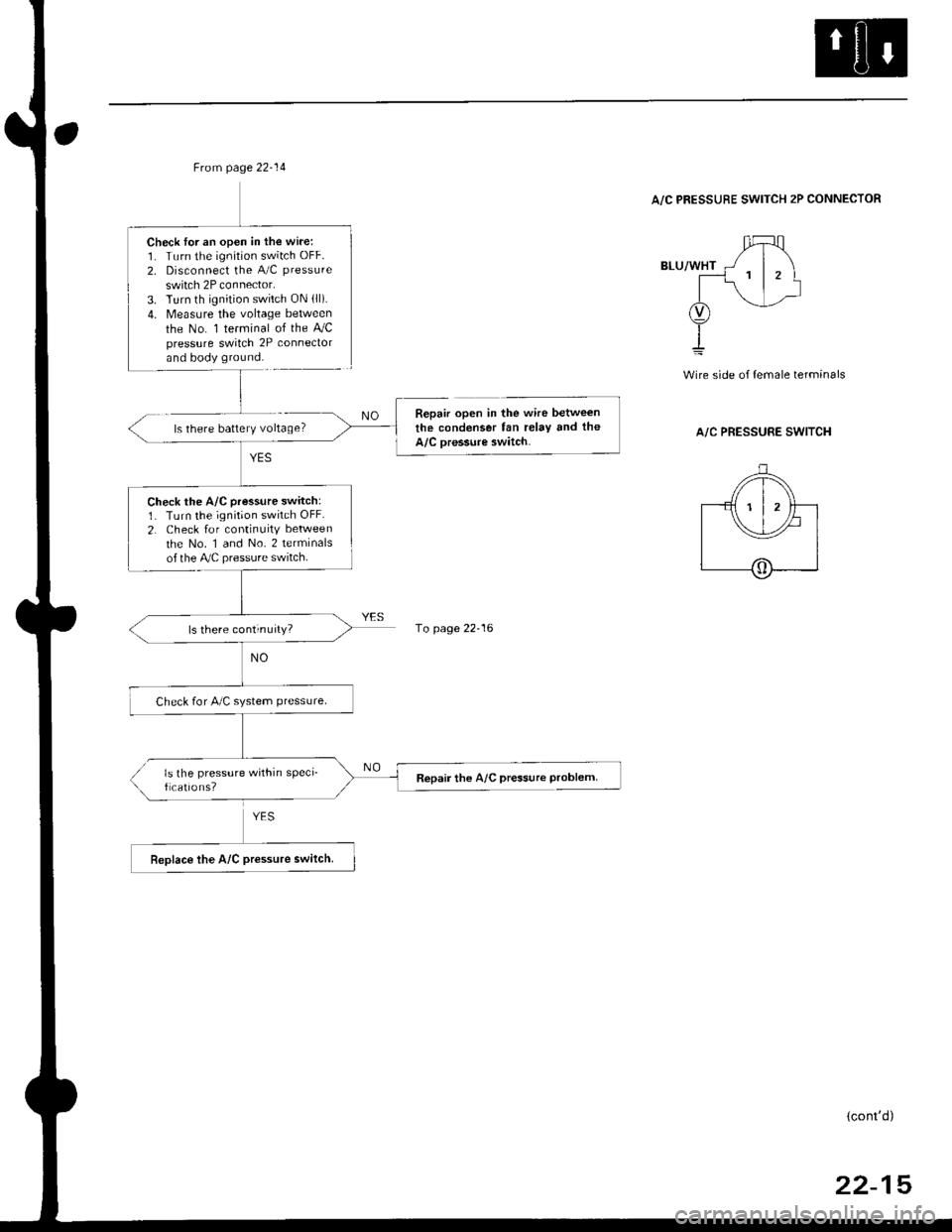
Check lor an open in the wire:1. Turn the ignition switch OFF.
2. Disconnect the A/C pressure
switch 2P connector.3. Turn th ignition switch ON lll).4. Measure the voltage between
the No. 1 terminal of the AJCpressure switch 2P conneclorand body ground.
Check the A/C pressure switch:1. Turn the ignition switch OFF.
2. Check for continuity between
the No. 1 and No. 2 terminalsof the Ay'C pressure switch.
ls there continuity?
Check for A/C system ptessure.
ls the pressure within sPeci_f cations?Repair the A/C pressure Problem
A/C PRESSURE SWITCH 2P CONNECTOR
ls there battery voltage?
wire side of {emale terminals
A/C PRESSURE SWITCH
Repair open in the wire between
the condenser fan relay tnd the
A/C oressure switch.
1o page 22-16
(cont'd)
22-15
Page 1440 of 2189
Troubleshooting
Gompressor (cont'dl
'96 -98 models:
ECM/PCM CONNECTOR C 13lPI
Wire side ot female terminals
'9!t - 00 mod.bi
ECM/PCM CONNECTOR A I32P)
Wire side ot female terminals
*How to use the backprobe setsConnect the backprobe adapters to the stacking patch cords, andconnect the cords to a multimeter. Using the wire insulation as aguide for the contoured tip of the backprobe adapter, gently slidethe tip into the connector from the wire side until it comes in con-tact with the terminal end ofthe wire {see section 11}.
From page 22-15
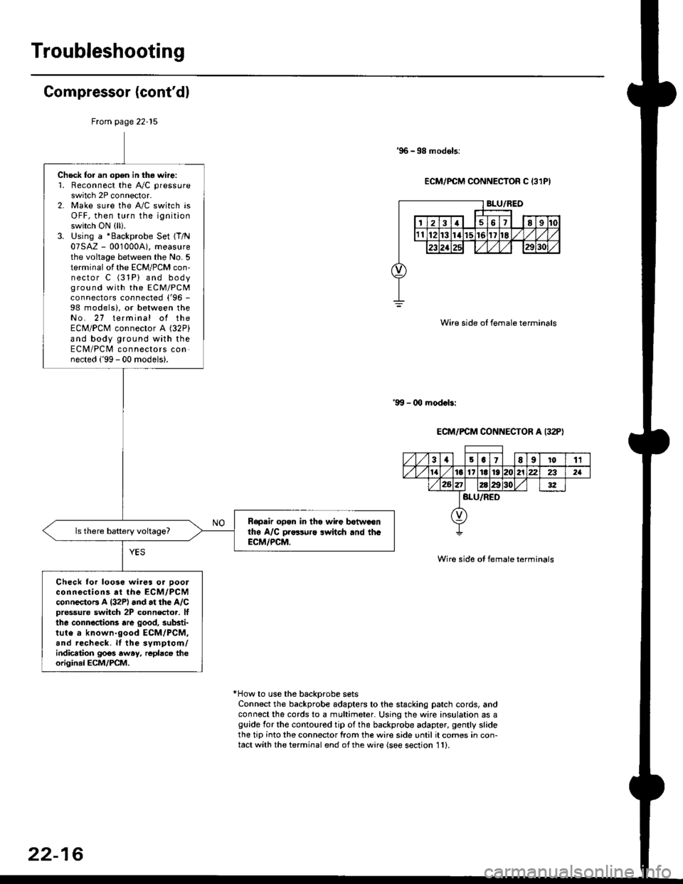
Check for an open in thg wire:'1. Reconnect the A"/C pressure
switch 2P connector.2. Make sure the A/C switch isOFF, then turn the ignitionswitch ON (ll).
3. Using a *Backprobe Set {T/N07SAZ - 001000A), measurethe voltage between the No. 5terminal of the ECM/PCM con-nector C (31P) and bodyground with the EcM/PcMconnectors connected ('96 -
98 models), or between theNo. 27 terminal of theECM/PCM connector A (32P)
and body ground with theECM/PCM connectors connected ('99 - 00 models).
Rapdir open in tho wi?e botwaonthe A/C pr..-ruro lwitch rnd th.ECM/PCM.
Check lor loo3e wires or ooolconnections at the ECM/PCMconnectoB A l32P) and at the A/Cpressure switch 2P connector, lfthe connections are good, substi-tute a known-good ECM/PCM,and recheck. lf the svmptom/indication goos away, repbce theoriginal ECM/PCM.
31501E91011
tat6l11E1921222321
BLU/RED
22-16
Page 1441 of 2189
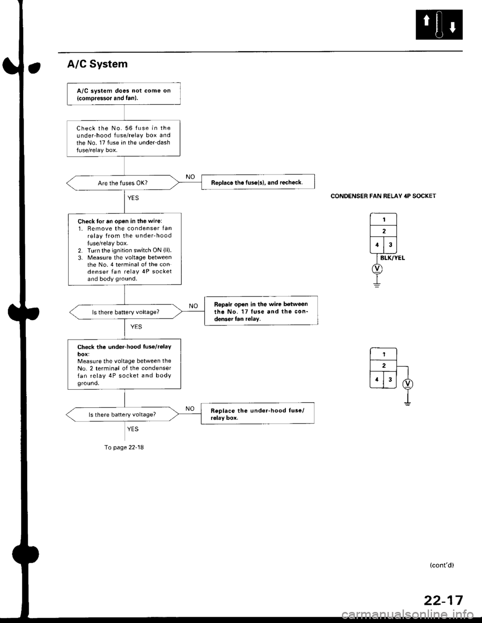
A/C System
CONDENSER FAN RELAY 4P SOCKET
A/C system does not come on
{comDressor and fan).
Check the No. 56 fuse in theunder'hood fuse/relay box andthe No. 17 fuse in the under-dashfuse/relay box.
ReDlace the fus6{s}, and recheck.
Check for tn open in the wire:
1. Remove the condenser lanrelay from the u nderhood
luse/relay box.2. Turn the ignition switch ON {lli.3- Measure the voltage betweenthe No. 4 terminal of the condenser fan relav 4P socketand body ground.
Repair open in the wire between
the No. 17 fuse and the con-denser fan r6lay,
Check the under-hood fus€/r6laybox:Measure the voltage between the
No. 2 terminal of the condenser
fan relay 4P socket and bodyground,
YES
Io page 22-18
(cont'd)
Page 1442 of 2189
Troubleshooting
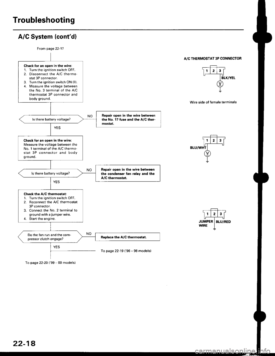
A/C System (cont'd)
From page 22-11
. _Ff,, __
I11213[
,r,il*"-T",-.r-'..owrRE I
To page 22-19 1'96 - 98 models)
A/C THERMOSTAT 3P CONNECTOR
Wire side oI female terminals
Check tor an open in the wire:1. Turn the ignition switch OFF.2. Disconnect the A/C thermostat 3P connector.3. Turn the ignition switch ON (ll).
4. Measure the voltage betweenthe No. 3 terminal of the Ay'Cthermostat 3P connector andbody ground.
Repai. open in the wire betweentho No. 17 tuso and the A/C the.-mostat.
Check loi an open in the wi.e:Measure the voltage between theNo. 1 terminal of the A,/C thermostat 3P connector and bodyground,
Ropair open in the wire betwoenthe condedlo. lan rolay and theA/C thormostat.
ls there battery voltage?
Check the A/C th6rmostat:1. Turn the ignition switch OFF.2. Reconnect the A,/C thermostat3P connector.3. Connect the No. 2 terminal toground with a iumperwire.4. Start the engine.
Do the fan run and the com-pressor clutch engage?
To page 22-20 ('99 - 00 models)
22-18
Page 1443 of 2189
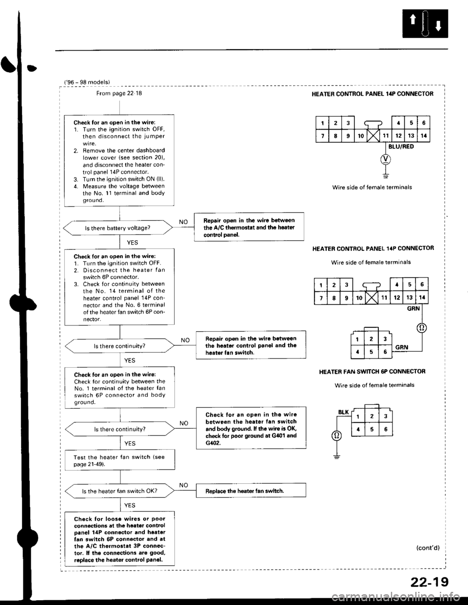
Ftom page 22 18
Check tor an open in the wire:1. Turn the ignition switch OFF,then disconnect the iu mper
2. Remove the center dashboardlower cover lsee section 20),
and disconnect the heater con'
trol panel 14P connector.
3. Turn the ignition switch ON (ll).
4. Measure the voltage betweenthe No. 11 terminal and bodyground.
Repair op6n in the wire bstween
the A/C th€rmostat and th6 hoater
control panel.
Check lor an open in the wire:
1. Turn the ignition switch OFF.2. Disconnect the heater Ian
switch 6P connector,3. Check for continuity between
the No. 14 terminal of theheater control panel 14P con_nector and the No.6 terminalof the heater fan switch 6P con-nector.
Repair open in the wiro betweGnthe heal.r control Panel and theheater fan switch.
Check for an open in thG wire:Check for continuity between theNo. 1 terminal of the heater lanswatch 6P connector and bodYground.
Chock tor an open in tho wir€
between the heater lan switch
and body ground. lf the wire is OK,check for poor ground at G401 sndG402.
ls there continu;ty?
ReDlace the heater tan switch.ls the heater fan switch OK?
Check for loose wiaes or poor
connections at the heater controloanel 14P connoctor and hoetertan 3witch 5P conn€clor and atthe A/C thermostet 3P connec-tor. ll the connections are good,
raplace the heator control Panel.
r'oA - qe m^.lalal
HEATER CONTROL PANEL lilP CONNECTOR
tra6
7II'o lx't1121314
BLU/RED
Wire side of female terminals
HEATER CONTROL PANEL 1'P CONNECTOR
Wire side of female terrninals
HEATER FAN SW]TCH 6P CONNECTOR
Wire side of female terminals
(cont'd)
12;--?45
7I10X'll121314
GRN
123
a56GRN
22-19
Page 1444 of 2189
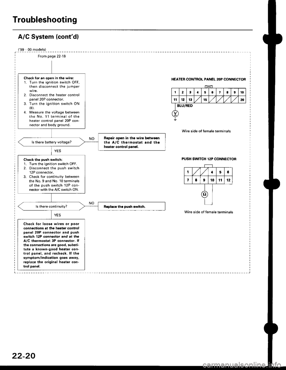
Troubleshooting
('99 00 models)
From page 22 18
Check lor an open in the wire:1. Turn the ignition switch OFF,then disconnect the ju mper
2. Disconnect the heater controlpanel 20P connector.3. Turn the ;gnition switch ON{
i.4. Measure the voltage betweenthe No. 11 terminal of theheater control panel 20P con-nector and body ground.
Ropai. opan in tho wira batwaonthe A/C thermostat and thehoater control oanol.ls there battery voltage?
Check the push switch:1. Turn the ignition switch OFF.2. Disconnect the push switch12P connector.3. Check for continuity betweenthe No. I and No. 10 terminalsof the push switch 12P con-nector with the A/C switch ON.
Check for loose wi.es or poor
connections el the hgater controlpanel 20P connector and pushswitch 12P connector and at theA/C thermostat 3P connector. Ittha connections are good, substi-tute a known-good heatea con-trol pan€|, and recheck. lf thesymptom/indication goe3 away,replace lhe original healer con-trol oan€|,
HEATER CONTROL PANEL anP CONNECTOR
Wire side of temale terminals
PUSH SW]TCH 12P CONNECTOR
Wire side of female terminals
,/1,/156
7819t01112
I
I
I
Page 1448 of 2189
A/C System Service
Performance Test
The performance test will help determine if the air con-
ditioner system is operating within specifications.
Use only service equipment that is U.L.-listed and is cer-
tified to meet the reouirements of SAE J2210 to remove
HFC-134a (R-134a) from the air conditioner system.
CAUTION: Exposure to air conditionor rofrigerant and
lubricant vapor or mist can irrilalo €yes, nose and
throat. Avoid breathing tho air conditioner rstrigerrnt
and lubricant vapor or mist,
lf accidental system discharge occurs, ventilate work
area before resuming service.
R-134a service equipment or vehicle air conditioner sys-
tems should not be pressure tested or leak tested with
compressed air.
@ some mixtur$ of air and R-134a have been
shown lo b9 combustible rt glgvatad pr€ssur63 and can
resull in tire 01 oxplosion causing inlury ot property
damage. Never uao compre33ed air to pressure t99t R-
134a ssrvico 6quipmsnt or vohicla air conditioner sys-
tems.
Additional health and safety information may be obtained
from the refrigerant and lubricant manufacturers.
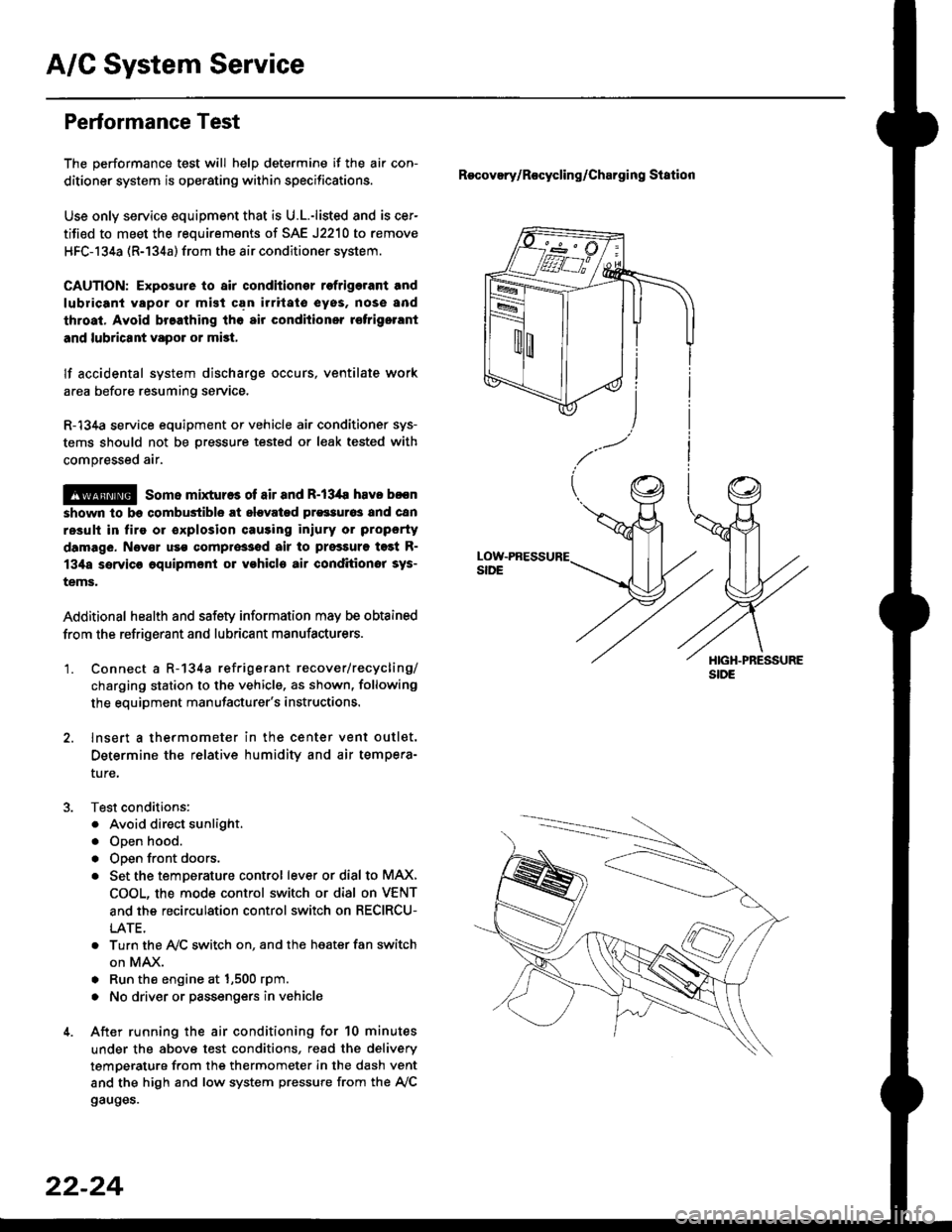
'1. Connect a R-134a refrigerant recover/recycling/
charging station to the vehicle, as shown, following
the equipment manufacturer's instructions.
2. lnsert a thermometer in the center vent outlet.
Determine the relative humidity and air tempera-
ture,
Test conditions:
. Avoid direct sunlight.
. Open hood.
. Open front doors.
. Set the temDerature control lever or dial to MAX,
COOL, the mode control switch or dial on VENT
and the recirculation control switch on RECIRCU-
LATE.
. Turn the A,/C switch on. and the heater fan switch
on MAX.
. Run the engine at 1,500 rpm.
. No driver or passengers in vehicle
After running the air conditioning for 10 minutes
under the above test conditions, read the delivery
temperature from the thermometer in the dash vent
and the high and low system pressure from the A,/C
gauges.
Recovery/Rocycling/Charging Station
22-24