Switch ignition HONDA CIVIC 2000 6.G Workshop Manual
[x] Cancel search | Manufacturer: HONDA, Model Year: 2000, Model line: CIVIC, Model: HONDA CIVIC 2000 6.GPages: 2189, PDF Size: 69.39 MB
Page 2032 of 2189
Power Door Locks (contd)
Doors Do Not Unlock Or Lock With
The Transmitter
1. Do the door's unlock and lock when usinq the
driver's door lock switch?
Yes - Go to the next step.
No - Repair the power door lock system.
2. Does the transmitter LED come on when anv of
the buttons are oressed?
Yes - Go to the next steo.
No - Check the transmitter battery, then retest.
It lhe doors still do not unlock or lock with
the transmitte( go to the next step.
Recheck with a known good transmitter
reprogrammed to the vehicle. Does the system
work properly in all modes.
Yes - Replace and program the transmitter,
then retest. Use the procedure on page
1 30-4 f or transmitter programming.
No- Gotothe next step.
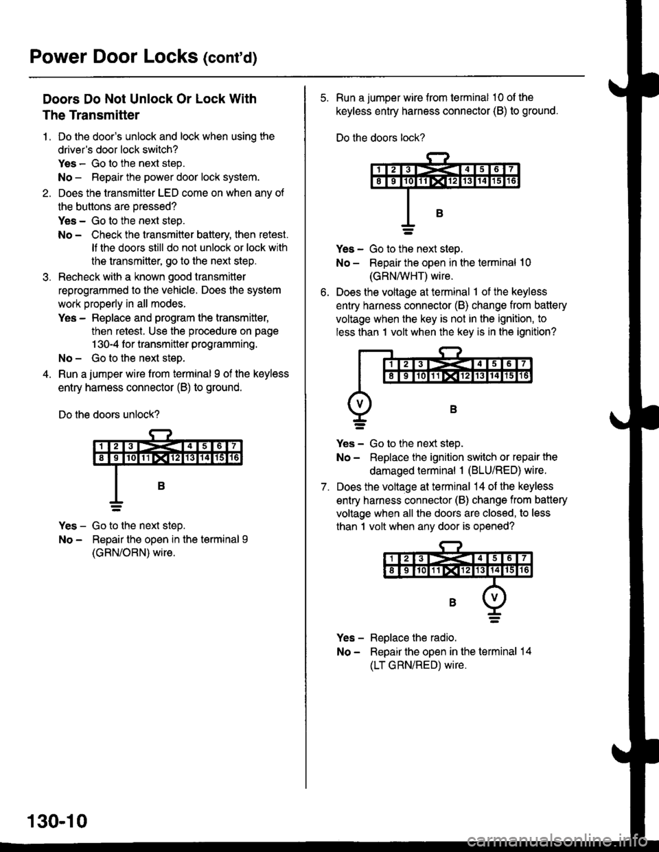
Run a jumper wire from terminal I of the keyless
entry harness connector (B) to ground.
Do the doors unlock?
Yes - Go to the next steD.
No - Repair the open in the terminal 9
(GRN/ORN) wire.
130-10
5. Run a jumper wire from terminal 10 ol the
keyless entry harness connector (B) to ground.
Do the doors lock?
ves - Go to ttie next steo.
No - Repair the open in the terminal 10
(GRN/vVHT) wire.
Does the voltage at terminal 1 of the keyless
entry harness connector (B) change from battery
voltage when the key is not in the ignition, to
less than 1 volt when the key is in the ignition?
7.
Yes - Go to the next step.
No - Replace the ignition switch or repair the
damaged terminal 1 (BLU/RED) wire.
Does the voltage at terminal 14 of the keyless
entry harness connector (B) change from battery
voltage when all the doors are closed, to less
than 1 volt when any door is opened?
Yes - Replace the radio.
No - Repair the open in the terminal 14
(LT GRN/RED) wire.
Page 2034 of 2189
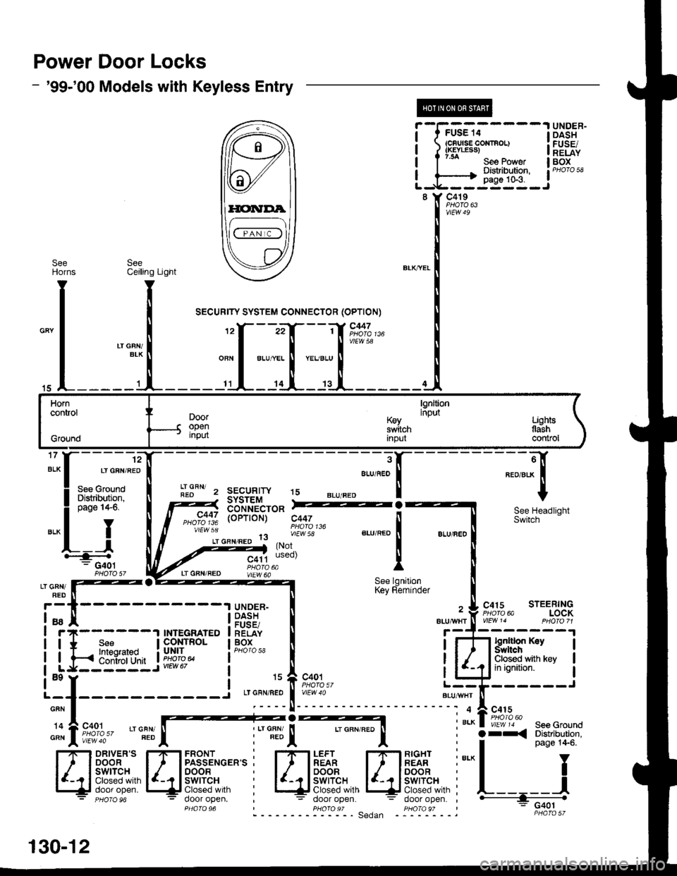
Power Door Locks
- '99-'00 Models with Keyless Entry
@
i-f?G;.-----l
i ?f*""t:::", i
L-,H-i{*q-J
UNDER-DASHFUSE/RELAYBOX
8 Y C419
vtEW49
SeeHOrns
15
Horncontrol
Grgund
lgnltioninputDooropeninput
K€yswitchInpul
Lighlstlashcontrol
17
ALK
c447
vtEw 5a
'12
LT GFN/RED
See GroundDistribution,page I +6,
YI
IF--.--.r-G401
I
3
ALU/f,EO
!r.lFN' z sEcuglw t5REOSYSTEMtsb'*nii'cro* =2
a, o"nt"ao 1lvlEw 58
(Not
(oPTroN) c447See HeadlightSwitch
C415 STEERINGPHora 6a LOCKVlEtt\/ 14 PHO|O 71
lgntlion KaySYrftchClosed with keyin ignition.
LT GRN/FED
LT GFN/REDSee lgnitionKey Reminder
UNDER-DASHFUSE/RELAYBOX
ALU/IVITT
a9
GFN
'14
GRN
130-12
Page 2036 of 2189
Power Door Locks (conrd)
- How the Circuit Works
Keyless Entry System
The keyless door locks combine the power door
locks with a remote key-fob transmitter. The keyless
door lock control unit receives direct inputs from the
ignition key switch, the passenger door switches,
and an indirect inDut from the driver's door switch
through the integrated control unit.
Power Door Locks
The power door lock system rs made up ot the
keyless door lock control unit, driver's door lock
switch, and individual door lock actuators. The
power door locks are controlled by the driver's door
lock switch and the driver's door lock actuator
switch.
Transmittel
The transmitter sends coded radio wave signals to
the keyless door lock conlrol unit when one of its
buttons is pressed. Each transmitter has a unique
code that must be 'laught" to the conlrol unit before
it can operate the door locks or any other function.
Up to 4 transmitters can be programmed to operate
the keyless door locks.
Door Locking
When you push the driveas door lock switch to the
lock position, ground is applied to the GRNMHT
wire to the keyless door lock control unit. The
control unit then applies battery voltage to the
WHT/RED wire and ground to the YEURED wire.
The passenger door lock actuators then activate to
lock the corresponding door locks.
When you lock the dnver's door with the key or door
lock knob, it is mechanically locked, and the driver's
door lock actuator switch applies ground to the
oower door lock control unit. The control unit then
applies battery voltage to the WHT/RED wire and
ground to the YEURED wire, activating the
passenger door lock actuators which lock the doors.
Door Locking with Transmitter
When you press the LOCK button on the remote
transmitter, the keyless door lock control unil applies
battery voltage to the WHT/RED wire and ground to
the YEURED wire. The passenger door lock
actuators then activate and lock the doors. A ground
signal is also applied to the BLU/RED wire to lock
the driver's door. lf any door is open, you cannot lock
it using the remote transmitter.
Door Unlocking
When you push the driver's power door lock switch
to the unlock position, ground is applied to the
GRN/ORN wire to the keyless door lock control unil.
The control unit then applies battery voltage to the
YEUREO and BLU/RED wires and oround to the
WHT/RED wire. The door lock actuators then
activate to unlock the doors.
When you unlock the driver's door with the key or
the door lock knob, it is mechanically unlocked; the
other doors do not unlock.
Door Unlocking with Transmitter
When you press the UNLOCK button on the remote
transmitter once, the keyless door lock control unit
applies battery voltage to the WHT/RED wire and
ground to the BLU/RED wire to unlock the driver's
door. When you press the UNLOCK button twice,
the control unit then applies ground to the YEURED
wires lo activate the passenger door locks. lf you do
not open a door within 30 seconds after unlocking
the doors with the transmitter, the doors
automatically relock.
Transmitter Programming
. Entering the programming mode cancels all
learned transmitter codes, so none of the
previously programmed transmitters will work.
You must reprogram all the transmitters once
you're in the programming mode.
. To keep the system from exiting the
programming mode, complete each step within 5
seconds of the previous step, and program the
transmitters within 10 seconds of each other.'1 . Turn the ignition switch ON (ll).
2. Press the "LOCK" or "UNLOCK" button on one
of the transmitters. (A non-programmed
transmitter can be used for this step.)
3. Turn the ignition switch OFF (0).
4. Repeat steps 1, 2, and 3 two more times with
the transmitter used in step 2.
5. Turn the ignition switch ON (ll).
6. Press the "LOCK" or "UNLOCK" button on the
same transmitter. Check that the power door
locks cycle to confirm that you're in the
programmrng mooe.
7. Press the "LOCK" or "UNLOCK" button on each
lransmitter. (You can program up to four
lransmitters per vehicle.) Check that the power
door locks cycle after you push each transmitter
button, contirming that the system has accepted
the transmitter's code.
Beep On/Off Feature
1 . Press and hold the LOCK and OPTION buttons
on the transmitter.
2. Watch the transmitter's LED:
One flash: BeeD activated.
Two flashes: Beep deactivated.
130-14
Page 2038 of 2189
Power Door Locks (cont'd)
Keyless Door Lock Control Unit Input Test
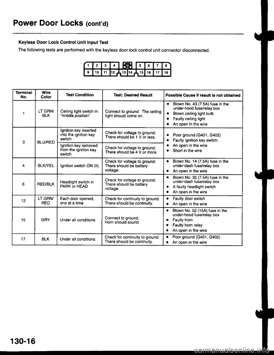
The following tests are performed with the keyless door lock control unit connector disconnected.
TerminalNo.WireColorTest ConditionTest: Desir€d ResultPossible Cause if result ls not obtain€d
1LT GRN/BLKCeiling light switch in"middle position"Connect to ground: The ceilinglight should come on.
aBlown No. 43 (7.5A) luse in theunder-hood tuse/relay box
Blown ceiling light bulb
Faulty ceiling light
An open in the wire
o
a
a
3BLU/RED
lgnition key insertedinto the ignition keyswitch
Ch€ck lor voltage to ground:There should be I V or less.aPoor ground (G401, G402)
Faulty ignition key switch
An open in the wire
Short in the wire
a
a
o
lgnition key removedlrom the ignition keyswitch
Check for voltage to ground:There should be 4 V or more.
BLfiEtlgnition switch ON (ll)Check lor voltage to ground:
There should be batteryvoltage.
. Blown No. 14 (7.54) fuse in theunder-dash fuse/relay box
. An open in the wire
bREO/BLKHeadlight switch inPARK OT HEAD
Check for voltage to ground:
There should be batteryvoltage.
aBlown No. 32 (7.5A) luse in theunder-dash fuse/relay box
A faulty headlight switch
An open in the wire
a
o
LT GRN/RED
Each door opened,one at a timeCheck lor continuity to ground:
There should be continuitv.
oFaulty door switch
An open in the wireo
15GRYUnder all conditionsConnect to ground:
Horn should sound.
. Blown No. 52 (154) fuse in theunder-hood fuse/relay box
. Faulty horn
. Faulty horn relay
o An open in the wire
BLKUnder all conditionsCheck lor continuity to ground:
There should be continuity.
aPoor ground (G401 , G402)
An open in the wirea
130-16
Page 2040 of 2189
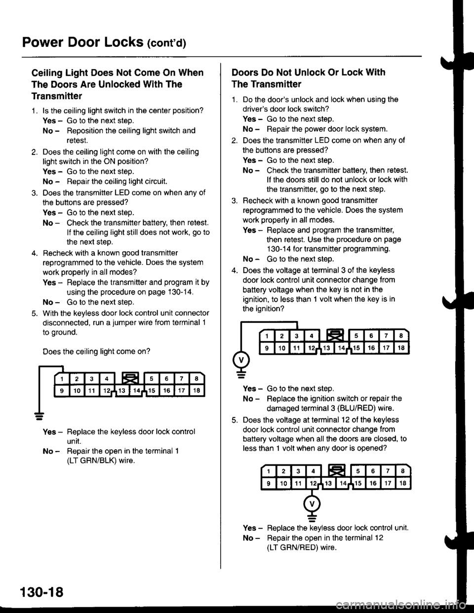
Power Door Locks (cont'd)
Ceiling Light Does Not Come On When
The Doors Are Unlocked With The
Transmitter
1 . ls the ceiling light switch in the center position?
Yes - Go to the next steD.
No - Reposition the ceiling light switch and
relesI.
2. Does the ceiling light come on with the ceiling
light switch in the ON position?
Yes - Go to the next steo.
No - Repau the ceiling light circuit.
3. Does the transmitter LED come on when anv of
the buttons are oressed?
Yes - Go to the next step.
No - Check the transmitter battery, then retest.
lf the ceiling light still does not work, go to
the next step.
4. Recheck with a known good transmitter
reprogrammed to the vehicle. Does the system
work properly in all modes?
Yes - Replace the transmitter and program it by
using the procedure on page 130-14.
No - Go to the next step.
5. With the keyless door lock control unit connector
disconnected, run a jumper wire from terminal 1
to ground.
Does the ceiling light come on?
Yes - Replace the keyless door lock control
un [.
No - Repair the open in the terminal I
(LT GRN/BLK) wire.
130-18
Doors Do Not Unlock Or Lock With
The Transmitter
1 . Do the door's unlock and lock when using the
drivefs door lock switch?
Yes - Go to the next steo.
No - Repair the power door lock system.
2. Does the transmitter LED come on when anv of
the buttons are oressed?
Yes - Go to the next steo.
No - Check the transmitter batlery, then retest.
lf the doors still do not unlock or lock with
the transmitter, go to the next step.
3. Recheck with a known good transmitter
reprogrammed to the vehicle. Does the system
work properly in all modes.
Yes - Replace and program the transmitter,
then retest. Use the procedure on page
1 30-1 4 for transmitter programming.
No - Go to the next steo.
4. Does the voltage at terminal 3 of the keyless
door lock control unit connector change from
battery voltage when the key is not in the
ignition, to less than 1 volt when the key is in
the ignition?
Yes - Go to the next step.
No - Replace the ignition switch or repair the
damaged terminal 3 (BLU/RED) wire.
5. Does the voltage at terminal 12 of the keyless
door lock control unit connector change from
battery voltage when all the doors are closed, to
less than I volt when any door is opened?
Replace the keyless door lock control unit.
Reoair the ooen in the terminal 12
(LT GRN/RED) wire.
Page 2055 of 2189
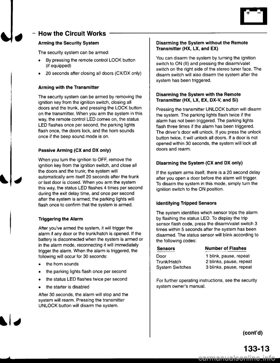
How the Circuit Works
Arming the Security System
The security system can be armed:
r By pressing the remote control LOCK button
(if equipped)
. 20 seconds atter closing all doors (C)UDX only)
Arming with the Transmitter
The security system can be armed by removing the
ignition key from the ignition switch, closing all
doors and the trunk, and pressing the LOCK button
on the transmitter. When you arm the system in this
way, the remote control LED comes on, the status
LED flashes once per second, the parking lights
flash once. the doors lock. and the horn sounds
once if the beeo sound mode is on.
Passive Arming (CX and Dx only)
When you turn the ignition to OFF, remove the
ignition key from the ignition switch, and close all
the doors and the trunk; the system will
automatically arm itself 20 seconds after the trunk
or last door is closed. When you arm the system
this way, the status LED tlashes 4 times per second
during the exit delay time, and once per second
after the system is armed; the parking lights will
flash once to confirm that the system is armed.
Triggering the Alarm
Atter you've armed the system, it will trigger the
alarm if any door or the trunldhatch is opened. lf the
battery is disconnected when the system is armed or
in the alarm mode, reconnecting it will immediately
trigger the alarm. When the alarm is triggered, the
following will occur for 30 seconds:
. the horn sounds
o the parking lights flash once per second
. the status LED flashes hvice oer second
. the starter is disabled
After 30 seconds, the alarm will stop and the
system will rearm. Pressing the transmitter
UNLOCK button will disarm the svstem.
tlr
133-13
Disarming the System without the Remote
Transmitter (HX, LX, and EX)
You can disarm the system by turning the ignition
switch to ON (ll) and pressing the disarm/valet
switch on the right side ol the stereo tuner face. The
disarm switch will also disarm the svstem after the
system has been triggered.
Disarming the System with the Remote
Transmitter (Hx, Lx, Ex, DX-V, and Si)
Pressing the transmitter UNLOCK button will disarm
the system. The parking lights llash t\ivice if the
alarm has not been tnggered. The parking lights
flash three times if the alarm has been triggered.
The driver's door will unlock. lf you press the unlock
button twice, it will unlock all doors. lf a door is not
opened within 30 seconds, the system will lock all
doors and rearm.
Disarming the System (CX and DX only)
lf the system arms itself, there is a 20 second delay
after you open a door before the alarm will trigger.
To disarm the system in this mode, simply turn the
ignition switch to the ON position
ldentitying Tripped Sensors
The system identifies which sensor trips the alarm
by flashing the status LED. To display the trip
sensor flash code, press the disarm/valet switch 3
times within 5 seconds after the system has been
disarmed. The status sensor will blink according to
the followino codes:
SensorsNumber of Flashes
Door
TrunldHatch
System Switches
1 blink, pause, repeat
2 blinks, pause, repeat
3 blinks, pause, repeat
For further operating instructions, see the security
syslem owner's manual.
(cont'd)
Page 2057 of 2189
Ir
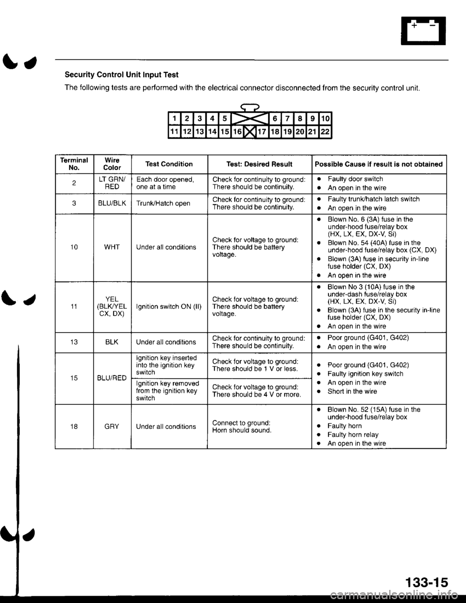
Security Control Unit Input Test
The following tests are performed with the electrical conneclor disconnected from the security control unit.
\;
12345X67I910
1112131415rol171819202122
TerminalNo.WireColorTest ConditionTest: Desired ResultPossible Cause il result is not obtained
2LT GRN/REDEach door opened,one at a timeCheck for conlinuity to ground:
There should be continuity.
Faulty door switch
An open in the wirea
3BLU/BLKTrunUHatch openCheck for continuity to ground:
There should be continuity.
aFaulty trunldhatch latch switch
An open in the wirea
10WHTUnder all conditionsCheck tor voltage to ground:
There should be batteryvoltage.
. Blown No. 6 (3A) fuse in theunder-hood fuse/relay box(HX, LX, EX, DX-V Si)
. Blown No. 54 (40A) fuse in theunder-hood fuse/relay box (CX, DX)
. Blown (3A) fuse in security in-linefuse holder (CX, DX)
. An open in the wire
11YEL(BLK/YEL
cx, DX)lgnition switch ON (ll)Check for voltage to ground:
There should be batteryvoltage.
. Blown No 3 (10A) fuse in theunder-dash tuse/relay box(HX, LX, EX, DX.V, Si)
. Blown (3A) fuse in the security in-linefuse holder (CX, DX)
. An open in the wire
BLKUnder all conditionsCheck for continuity to ground:
There should be continuity.
aPoor ground (G401, G402)
An open in the wirea
t5BLU/RED
lgnition key insertedinto the ignition keyswitch
Check for voltage to ground:
There should be 1 V or less.aPoor ground (G401, G402)
Faulty ignition key switch
An open in the wire
Short in the wire
a
a
algnition key removedfrom the ignition keyswitch
Check for voltage to ground:
There should be 4 V or more.
18GRYUnder all conditionsConnect to ground:
Horn should sound.
. Blown No.52 (15A) luse in theunder-hood luse/relay box
. Faulty horn
. Faulty horn relay
. An open in the wire
133-15
Page 2060 of 2189
Security System (cont'd)
Security System Does Not Work ln Any
Mode (CX, DX)
1. ls luse 54 (in the under-hood fuse box) OK?
Yes - Go to the next step.
No - Repiace the blown fuse, then go to the
next step.
2. ls the fuse in the securiiy in-line fuse holder OK?
Yes - Go to the next step.
No - Replace the blown fuse, then go to next
srep.
3. Does either fuse blow again?
Yes - Locate and repair the short.
No - Retest the system.
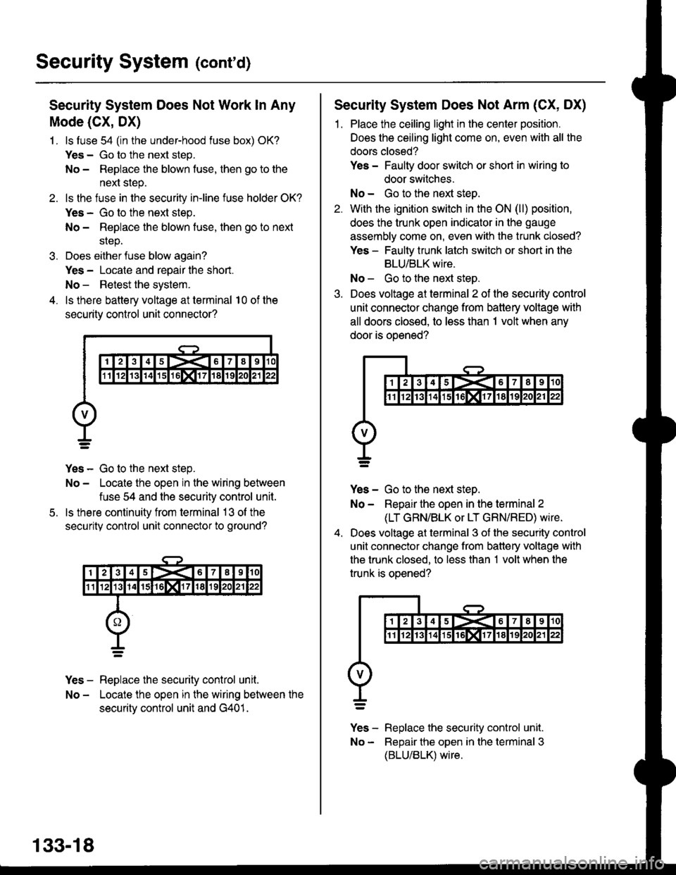
4. ls there battery voltage at terminal 10 of the
security control unit connector?
Yes - Go to the next step.
No - Locate the open in the wiring between
fuse 54 and the security control unit.
ls there continuity from terminal 13 ol the
security control unit connector to ground?
Yes - Replace the security control unit.
No - Locate the open in the wiring between the
securitv control unit and G401.
5.
133-18
Security System Does Not Arm (CX, DX)
1. Place the ceiling light in the center position.
Does the ceiling light come on, even with all the
doors closed?
Yes - Faulty door switch or short in wiring to
door switches.
No - Go to the next steo.
2. With the ignition switch in the ON (ll) position,
does the trunk open indicator in the gauge
assembly come on, even with the trunk closed?
Yes - Faulty trunk latch switch or short in the
BLU/BLK wire.
No - Go to the next step.
3. Does voltage at terminal 2 of the security control
unit connector change from battery voltage with
all doors closed, to less than 1 volt when any
door is ooened?
Yes - Go to the next step.
No - Repair the open in the terminal 2
(LT GRN/BLK or LT GRN/RED) wire.
Does voltage at terminal 3 of the security control
unit connector change from battery voltage with
the trunk closed, to less than 1 volt when the
trunk is oDened?
v]" - R"pt"." tne security control unit.
No - Bepair the open in the terminal 3
(BLU/BLK) wire.
Page 2061 of 2189
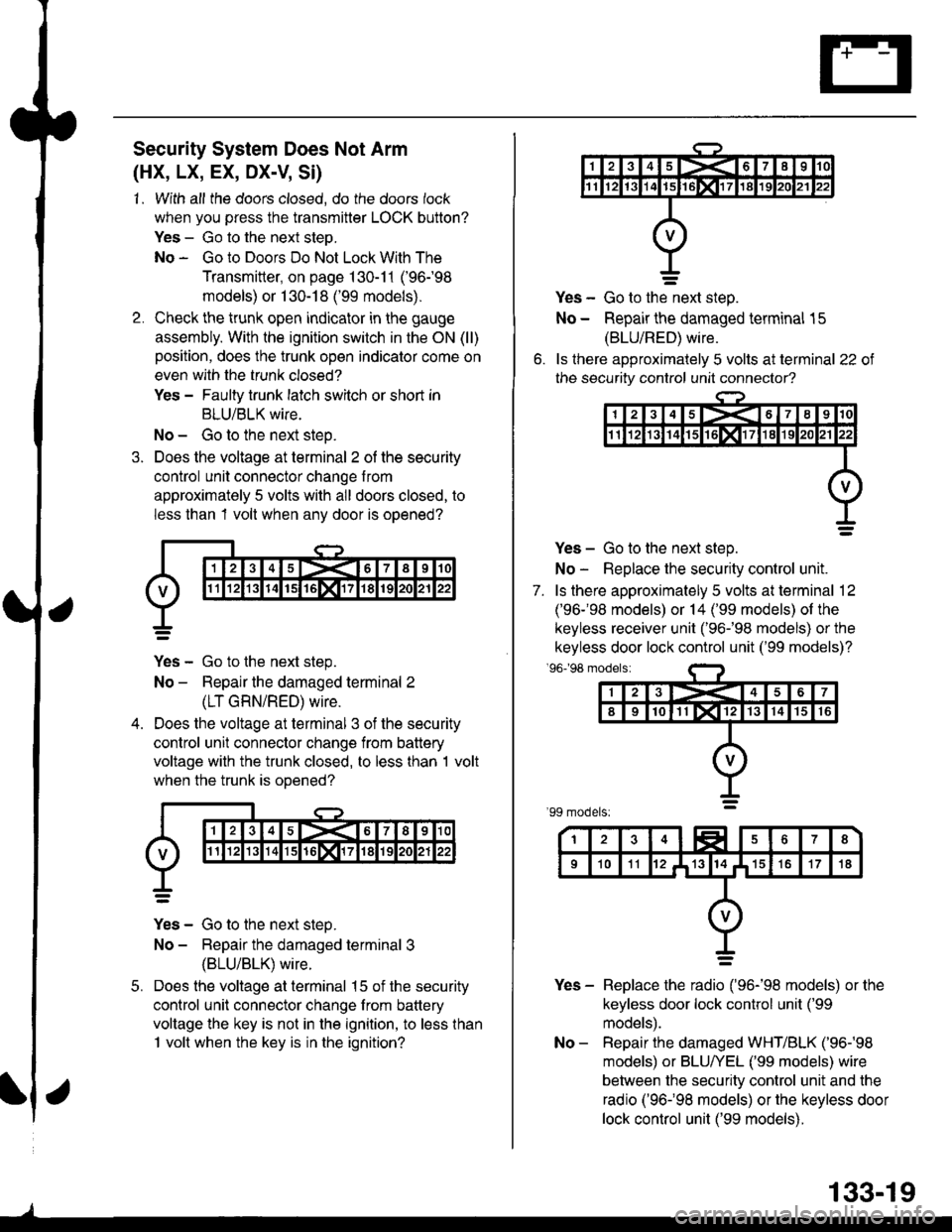
Security System Does Not Arm
(HX, LX, EX, DX-V, Si)
1. With all the doors closed, do the doors lock
when you press the transmitter LOCK button?
Yes - Go to the next steo.
No - Go to Doors Do Not Lock With The
Transmitter, on page 130-11 ('96-98
models) or 1 30-18 ('99 models).
Check the trunk open indicator in the gauge
assembly. With the ignition switch in the ON (ll)
position, does the trunk open indicator come on
even with the trunk closed?
Yes - Faulty trunk latch switch or shod in
BLU/BLK wire.
No - Go to the next steo.
Does the voltage at terminal 2 of the security
control unit connector change from
approximately 5 volts with all doors closed, to
less than 1 volt when any door is opened?
Yes - Go to the next step.
No - Repair the damaged terminal 2
(LT GRN/RED) wire.
Does the voltage at terminal 3 of the security
control unit connector change from battery
voltage with the trunk closed, to less than 1 volt
when the trunk is ooened?
Yes - Go to the next steo.
No - Repair the damaged terminal 3
{BLU/BLK) wire.
Does the voltage at terminal 15 of the security
control unit connector change from battery
voltage the key is not in the ignition, to less than
1 volt when the key is in the ignition?
5.
o.
Yes - Go to the-next step.
No - Repair the damaged terminal 15
(BLU/RED) wire.
ls ihere approximately 5 volts at terminal 22 of
the security control unit connector?
Yes - Go to the next step.
No - Replace the security control unit.
7. ls there approximately 5 volts at terminal 12
('96-'98 models) or 14 ('99 models) of the
keyless receiver unit ('96-�98 models) or the
keyless door lock control unit ('99 models)?'96198 modelsi
Yes - Replace the radio ('96-'98 models) or the
keyless door lock control unit ('99
models).
No - Repair the damaged WHT/BLK ('96-'98
models) or BLU/YEL ('99 models) wire
between the security control unit and the
radio ('96-�98 models) or the keyless door
lock control unit ('99 models).
133-19
Page 2062 of 2189
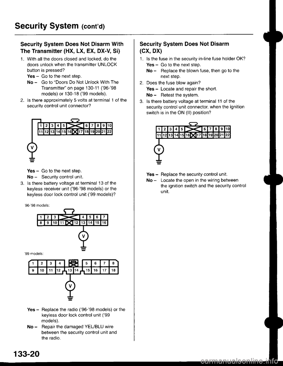
Security System (cont'd)
Security System Does Not Disarm With
The Transmitter (HX, LX, EX, DX-V, Si)
1 . With all the doors closed and locked, do the
doors unlock when the transmitter UNLOCK
button is pressed?
Yes - Go to the next step.
No - Go to "Doors Do Not Unlock With The
Transmitte/' on page 130-11 ('96-98
models) or 130-18 ('99 models).
2. ls there approximately 5 volts at terminal 1 of the
securitv control unit connector?
Yes - Go to the next step.
No - Security control unit.
3. ls there battery voltage at terminal 13 ofthe
keyless receiver unit ('96-�98 models) or the
keyless door lock control unit ('99 models)?
96.�98 models:
'99 models:
Yes - Beplace the radio ('96-'98 models) or the
keyless door lock control unit ('99
models).
No - Repair the damaged YEUBLU wire
between the security control unit and
the radio.
133-20
Security System Does Not Disarm
(cx, Dx)
1. ls the tuse in the security in-line luse holder OK?
Yes - Go to the next step.
No - Replace the blown fuse, then go to the
nexl sreD.
2. Does the fuse blow again?
Yes - Locate and repair lhe short.
No- Retest the system.
3. ls there battery voltage at terminal 11 of the
security control unit connector, when the ignition
switch is in the ON (ll) position?
Yes - Replace the security control unil.
No - Locate the open in the wiring between
the ignition switch and lhe securily control
unit.