Distributor HONDA CIVIC 2000 6.G Owner's Guide
[x] Cancel search | Manufacturer: HONDA, Model Year: 2000, Model line: CIVIC, Model: HONDA CIVIC 2000 6.GPages: 2189, PDF Size: 69.39 MB
Page 1872 of 2189
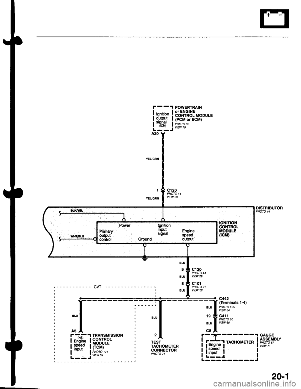
, r -.-- .l TBANSMTSS|ON
I igF"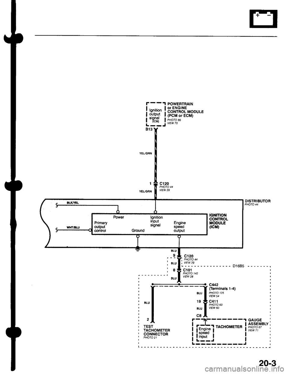
POWEBTRAINor ENGINECONTROL MODULE(PCM or ECM)
vtEw 70
lgnitionoulputsignatflcM)
I
YEUGBN
c'120
vtEw 29
DISTRIBUTOR
D1685 -------,
BLU
_9-
BLU
8
9LU
:'!'\?- - -
c101
vtEw 2a
----------<- c442
I frerminals 1-4]a|-u a olo'25 |I vlEw 54
19 g C411a PHOTA 60aru I vtrw ool,cBA- -.t GAUGF
i f#f rAcHoirErER ift?i,?""i
liitr" i !I L--J IL ---- - --- -J
TESTTACHOMETERcor.rNEcToRPHO|O2l
lgniiionnrpur Fh^ih-signal "p_il;Ground output
PrimaryoutPutcontsol
20-3
Page 1909 of 2189
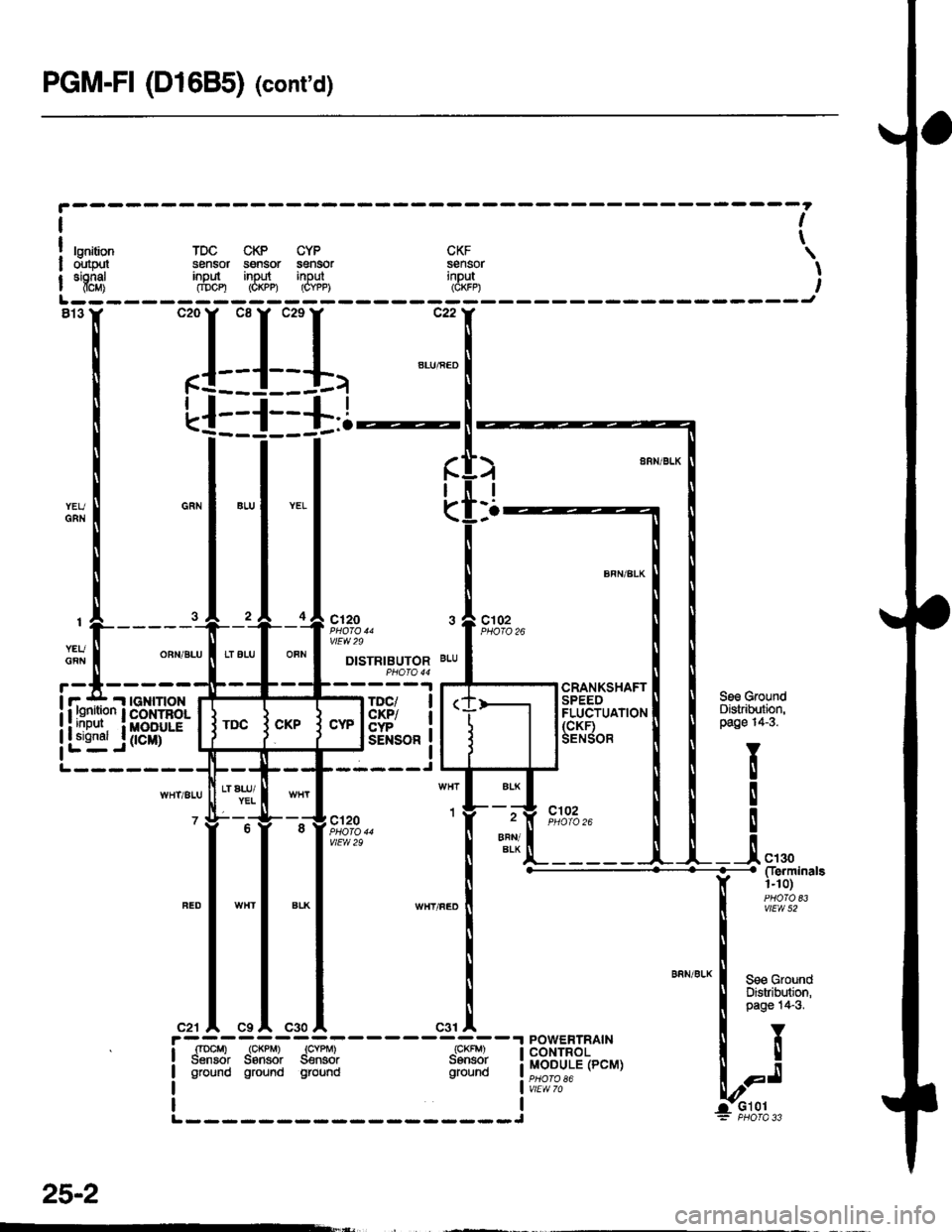
PGM-FI (D1685) (cont'd)
I
t
I
I
I
!rurr
| "'f8;i
h.
I
(
IGNITIONCONTBOLMOOULE
0cM)
ct20
vtEw 29
DISTRIBUTORPHO|O 44
TDC/c|(P/CYP
Se3 GroundDistrilutbn,page 14-3.
Y
!
!
!
__.!, ",,0
I
I
:nlI
POWERTRAINCONTROLMODULE (PCM)
c9 A C30
I
IL------
it-{ {ti'o'i""'"
|
"i1lg,*
I ."" u.*o
| 3l"J:uel
lt
b;,.i,,
!' -,'il"i -*-*i -.?'ii - - - - - -ri**i -''!
I Sensor Saflsor S€nsor Sansor !I ground ground ground ground !
25-2
Page 1980 of 2189
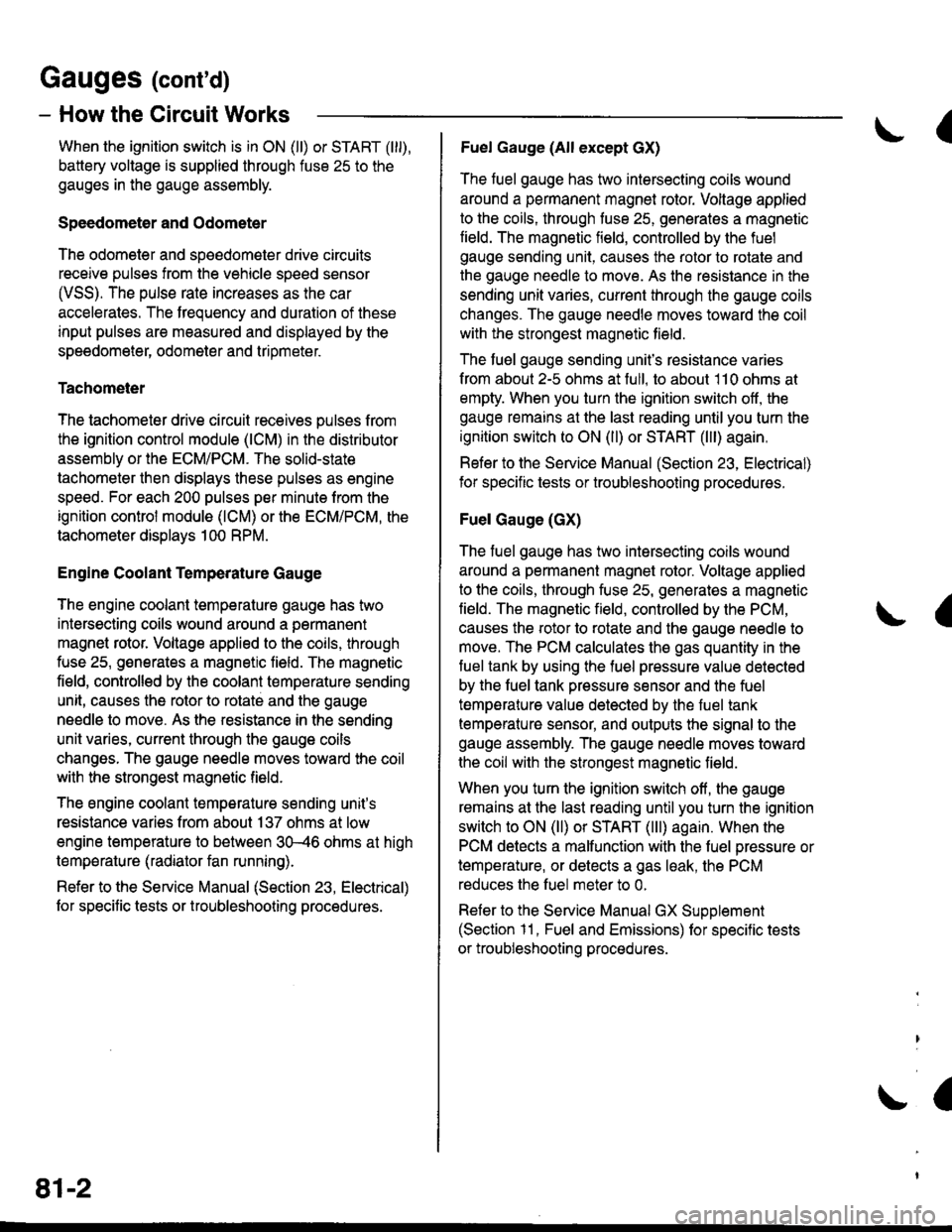
Gauges (cont'd)
- How the Gircuit Works
When the ignition switch is in ON (ll) or START (lll),
battery voltage is supplied through fuse 25 to the
gauges in the gauge assembly.
Speedometer and Odometer
The odometer and soeedometer drive circuits
receive pulses from the vehicle speed sensor
(VSS). The pulse rate increases as the car
accelerates. The frequency and duration of these
input pulses are measured and displayed by the
speedometer, odometer and tripmeter.
Tachometer
The tachometer drive circuit receives pulses from
the ignition control module (lCM) in the distributor
assembly or the ECM/PCM. The solid-state
lachometer then displays these pulses as engine
speed. For each 200 pulses per minute from the
ignition control modul€ (lCM) or the ECM/PCM, the
tachometer displays 100 RPM.
Engine Coolant Temperature Gauge
The engine coolant temperature gauge has two
intersecting coils wound around a permanent
magnet rotor. Voltage applied to the coils, through
fuse 25, generates a magnetic lield. The magnetic
field, controlled by the coolant temperature sending
unit, causes the rotor to rotate and the gauge
needle to move. As the resistance in the sending
unit varies, current through the gauge coils
changes. The gauge needle moves toward the coil
with the strongest magnetic field.
The 6ngine coolant temperature sending unit's
resistance varies from about 137 ohms at low
engine temperature to between 3H6 ohms at high
temperature (radiator fan running).
Refer to the Service Manual (Section 23, Electrical)
for specific tests or troubleshooting procedures.
81-2
(
Fuel Gauge (All except cX)
The fuel gauge has two intersecting coils wound
around a permanent magnet rotor. Voltage applied
to the coils, through tuse 25, generates a magnetic
field. The magnetic field, controlled by the fuel
gauge sending unit, causes the rotor to rotate and
the gauge needle to move. As the resislance in the
sending unit varies, current through the gauge coils
changes. The gauge needle moves toward the coil
with the strongest magnetic field.
The fuel gauge sending unit's resistance varies
from about 2-5 ohms at full, to about 110 ohms at
empty. When you turn the ignition switch off, the
gauge remains at the last reading until you turn the
ignition switch to ON (ll) or START (lll) again,
Refer to the Service Manual (Section 23, Electrical)
for specific tests or troubleshooting procedures.
Fuel Gauge (GX)
The fuel gauge has two intersecting coils wound
around a permanent magnet rotor. Voltage applied
to the coils, through fuse 25, generates a magnetic
field. The magnetic field, controlled by the PCM,
causes the rotor to rotate and the gauge needle to
move. The PCM calculates the gas quantity in the
fuel tank by using the fuel pressure value detected
by the tuel tank pressure sensor and the fuel
temperature value detected by the fuel tank
temperalure sensor, and outputs the signal to the
gauge assembly. The gauge needle moves toward
the coil with the strongest magnetic field.
When you turn the ignition switch off , the gauge
remains at the last reading until you turn the ignition
switch to ON (ll) or START (lll) again. When the
PCM detects a malfunction with the fuel pressure or
temperature, or detects a gas leak, the PCM
reduces the fuel meter to 0.
Refer to the Service Manual GX Supplement
(Section 11 , Fuel and Emissions) for specific tests
or troubleshooting procedures.
a
a
Page 2115 of 2189
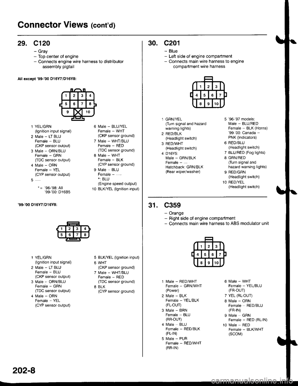
Connector Views (cont'd)
29. C120
- Gray- Top center of engine- Connects engine wire harness to distributor
assembly pigtail
All except '99-'00 016Y7/D16Y8:
l YEUGRN(lgnition input signal)
2 l\.4ale - LT BLUFemale - BLU(CKP sensor output)
3 Male - ORN/BLUFemale - GRN
[tDC sensor output)
4 l\.4ale - ORNFemale - YEL(CYP sensor output)
-= '96j98: All'99100: D1685
'99-'00 016Y7/D16Y8:
l YEUGRN(lgnition input signal)
2 Male - LT BLUFemale - BLU(CKP sensor output)
3 Male - ORN/BLUFemale - GRN
CIDC sensor output)
4 Male - ORNFemale - YEL
{CYP sensor output)
l\4ale - BLU/YELFemale - WHT(CKP sensor ground)
l\.4ale - WHT/BLUFCMAIE _ HtsL'(TDC sensor ground)
l\4ale - WHTFemale - BLK(CYP sensor ground)
Male - BLUFemale - . -*: BLU(Engine speed output)
BLK/YEL (lgnition input)
BLK/YEL (lgnition input)
WHT(CKP sensor ground)
Male - WHT/BLUFemale - RED
ffDC sensor ground)
BLK(CYP sensor ground)
10
202-8
30. c201
- Blue- Left side of engine compartment- Connects main wire harness to engine
compartment wire harness
l GRNA/EL(Turn signal and hazardwarning lights)
2 RED/BLK(Headlight switch)
3 REDAVHT(Headlight switch)
4 D16Y5:Male - GRN/BLKFemale -
Hatchbacki GRN/BLK
{Bear wipetwashe0
7
I
9b- 9/ mooets:lvlale - BLU/REDFemale BLK (Horns)'99-'00: Canada -
PNK (lndicators)
RED/BLU(Headlight switch)
BLU/RED (Fog lights)
GRN/RED
Cturn signal andhazard warning lights)
BED/GRN(Headlight switch)
RED/YEL(Headlight switch)
31. C359
- Orange- Right side ot engine compartment- Connects main wire harness to ABS modulator unit
10
l\4ale - REDAVHTFemale - GRNA/VHT(Power)
l\,4ale - BLKFemale - YEVBLK(FL-OUr)
Male - 8RNFemale BLIJ
{RR-OLrr)l\4ale BLUFemale - RED/BLK(FL-rN)
Male - PURFemale - RED&VHT(RR-rN)
6 Male - WHTFemale - YEUBLU(FR-OUr)
7 YEL (RL-OUr)
I Male - ORNFemale - RED/BLU(FR rN)
I Male GRNFemale - RED (RL-|N)
10 Male REDFemale - BLK,ryVHT(scol\,1)
Page 2143 of 2189
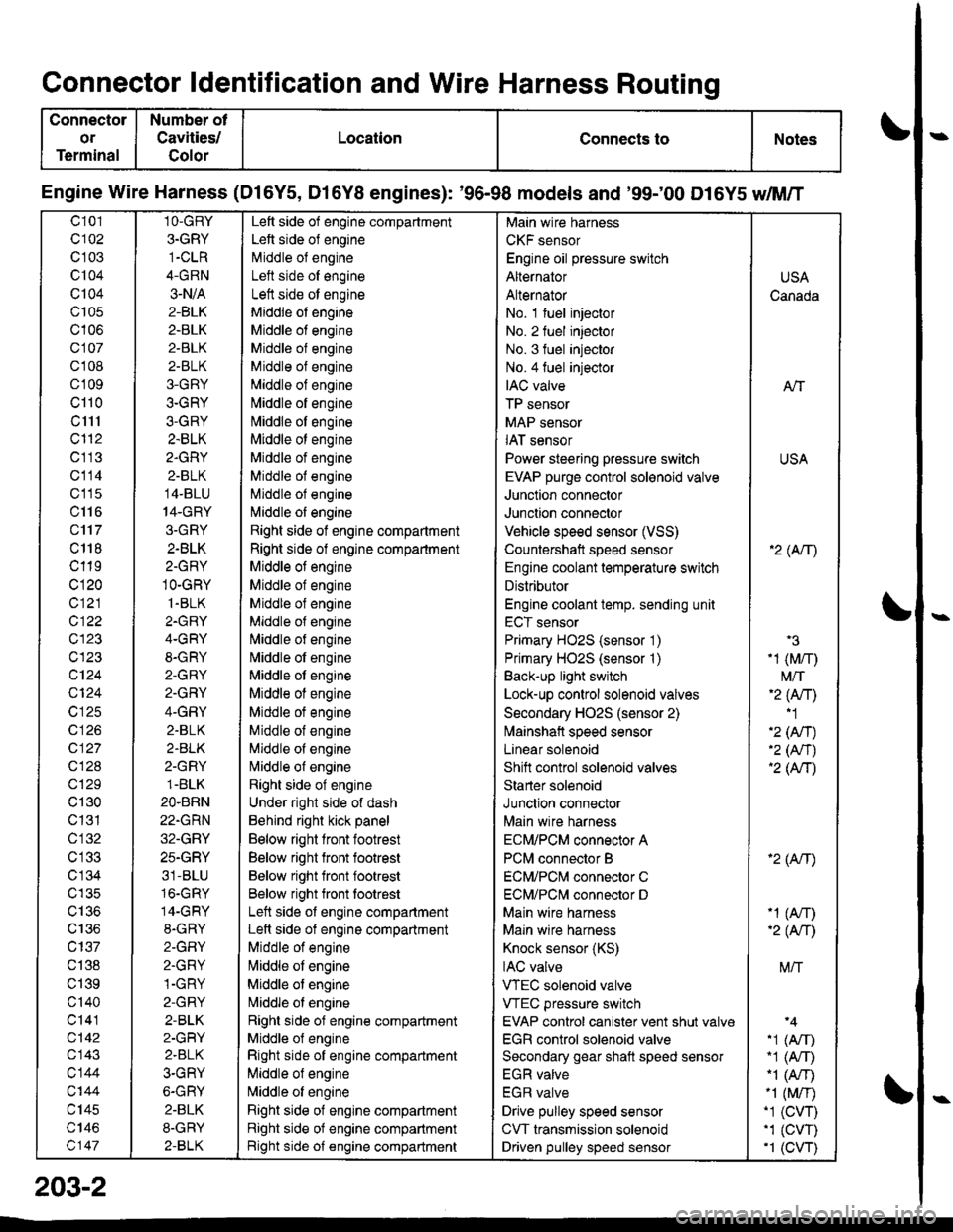
Connector ldentification and Wire Harness Routing
Connector
or
Terminal
Number ot
Cavities/
Golor
LocationConnects toNotes
Engine Wire Harness (Dl6Y5, D16Y8 engines): '96-98 models and '99;00 D16Y5 dM/T
c101
c102
c 103
c104
Q104
c105
c106
c107
cl 08
cl09
cl10
c1l1
cl'12
c113
c114
c'115
c116
c'117
c 118
c119
c120
c121
c122
c123
c123
c124
Q124
c125
c 126
c127
c128
c129
c130
c131
cl32
c 134
c135
c136
c137
c138
c139
c'140
c141
c142
c143
c144
c'|44
c145
c146
c147
1O-GRY
3.GRY
1-CLR
4-GRN
3-N/A
2-BLK
2-BLK
2-BLK
2-BLK
3-GRY
3-GRY
3-GRY
2.BLK
2.GRY
2-BLK
14-BLU
14-GRY
3.GRY
2-BLK
2-GRY
1O-GRY
1.BLK
2.GRY
4-GRY
8-GRY
2-GRY
2.GRY
4-GRY
2.BLK
2.BLK
2-GRY
1.BLK
2O.BRN
22.GRN
32.GRY
25.GRY
31-BLU
16.GRY
14-GRY
8.GRY
2-GFIY
2.GRY
1-GRY
2-GRY
2-BLK
2-GRY
2.BLK
3-GRY
6-GRY
2.BLK
8-GRY
2-BLK
Left side of engine compartment
Left side of engine
Middle of engineI att .i.la ^f an^i^6
Left side ot engine
Middle of engine
Middle of engine
Middle of engine
Middle of engine
Middle of engine
[,liddle of engine
Middle ot engine
Middle ot engine
Middle of engine
Middle of engine
Middle of engine
l\,liddle of engine
Right side of engine compartment
Right side of engine compartment
Middle ot engine
Middle of engine
Middle of engine
Middle of engine
l\,liddle of engine
Nliddle of engine
Middle ot engine
Middle of engine
Middle ot engine
Middle of engine
Middle of engine
Nliddle of engine
Right side of engine
Under right side of dash
Behind right kick panel
Below right front footrest
Below right front footrest
Below right front footrest
Below right front tootrest
Left side ot engine compartment
Left side of engine compartment
Middle of engine
liliddle ot engine
Middle of engine
Nriddle ol engine
Right side of engine compartment
Middle ol engine
Right side of engine compartment
Middle of engine
N,liddle of engine
Right side of engine compartment
Right side of engine compartment
Bight side of engine compartment
Main wire harness
CKF sensor
Engine oil pressure switch
Alternator
Alternator
No. 1 fuel injector
No. 2 fuel injector
No. 3 fuel injector
No.4 fuel injector
IAC valve
TP sensor
MAP sensor
IAT sensor
Power steering pressure switch
EVAP purge control sol€noid valve
Junction connector
Junction connector
Vehicle speed sensor (VSS)
Countershatt speed sensor
Engine coolant temperature switch
Distributor
Engine coolant temp. sending unit
ECT sensor
Primary HO2S (sensor '1)
Primary HO2S (sensor '1)
Back-up light switch
Lock-up control solenoid valves
Secondary HO2S (sensor 2)
lvlainshafl speed sensor
Lanear solenoid
Shift control solenoid valves
Starter solenoid
Junction connector
Main wire harness
ECM/PCM connector A
PCM connector B
ECM/PCNI connector C
ECM/PCl\,,| connector D
Main wire harness
Maln wire harness
Knock sensor (KS)
IAC valve
VTEC solenoid valve
VTEC pressure switch
EVAP control canister vent shut valv€
EGR control solenoid valve
Secondary gear shatt speed sensor
EGR valve
EGR valve
Drive pulley speed sensor
CVT transmission solenoid
Driven pulley speed sensor
USA
Canada
AlT
USA
'2( tr\
'3
-1 (M/r)
t\4/T'2 (Anl'1
'2 (An)'2 (Nr)'2 (AtT)
'2 (Atr)
-1 (An)-2( fi|
M/T
.1 (Arr).1 (A,T)"1 (A/r)-1 (M/r).1 (CVT),1 (cw)'1 (CVT)
203-2
Page 2145 of 2189
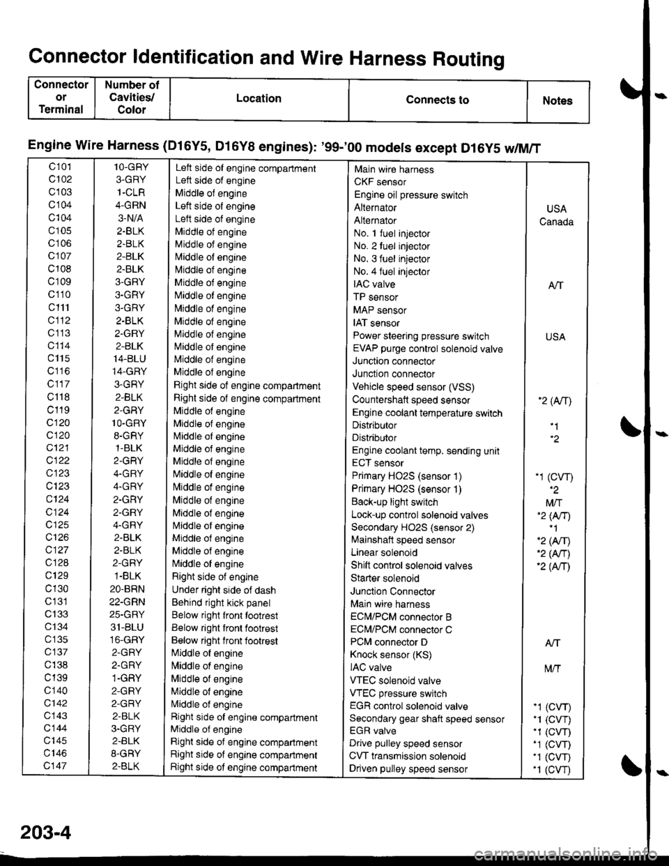
Connector ldentification and Wire Harness Routing
Connector
or
Terminal
Number of
Cavities/
Color
LocationConnects toNotes
Engine wire Harness (Dl6Y5, Dl6Y8 engines): '99-'00 models except D16y5 w/M/T
c 101
c102
c103
cl04
c104
c105
c106
c107
c108
c109
c110
c111
cl12
c1 13
c115
c117
c118
c119
c120
c120
c12'l
cl22
c123
c124
c124
c125
c126
c127
c128
c129
c130
c'131
c133
ct34
c 135
c137
c138
c139
c 140
c142
c143
c144
c'|45
c147
1O-GRY
3.GRY
1-CLR
4-GRN
3-N/A
2.BLK
2.BLK
2-BLK
2.BLK
3-GRY
3-GRY
3.GRY
2-BLK
2.GRY
2-BLK
14-BLU
14-GRY
3-GRY
2-BLK
2-GRY
1O-GRY
8.GRY,1-BLK
2.GRY
4.GRY
4.GRY
2.GRY
2.GRY
4.GRY
2.BLK
2-BLK
2-GRY
1-BLK
2O-BRN
22-GRN
25-GRY
31-BLU
16-GRY
2-GRY
2.GRY
1-GRY
2-GRY
2-GRY
2-BLK
3.GRY
2.BLK
8-GRY
2.BLK
Left side of engine compartment
Left side of engine
Middle of engine
Left side of engine
Left side of engine
Middle ot engine
Middle of engine
N,liddle of engine
l\4iddle of engine
Middle of engine
Niliddle of engine
N,,liddle of engine
Middle of engine
Middle of engine
Middle of engine
Middle of engine
Middle of engine
Rjght side of engine compartment
Right side of engine compartment
Middle of engine
Mlddle of engine
l\4iddle of engine
Middle of engine
Middle of engine
[iliddle of engine
lvliddle of engine
Middle of engine
Middle of engine
l\4iddle of engine
Middle ol engine
Middle of engine
N,liddle of engine
Right side of engine
Under right side of dash
Behind right kick panel
Below right front tootrest
Below right front footrest
Below right lront footrest
[iliddle of engine
l\,liddle of engine
Middle of engine
Middle of engine
L4iddle of engine
Right side of engine compartment
Middle of engine
Right side of engine compartment
Right side of engine compartment
Right side ot engine compartment
Main wire harness
CKF sensor
Engine oil pressure switch
Alternator
Alternator
No. 1 fuel injector
No. 2luel injector
No. 3 fuel injector
No.4 fuel injeclor
IAC valve
TP sensor
MAP sensor
IAT sensor
Power steering pressure switch
EVAP purge control solenoid valve
Junction connector
Junction connector
Vehicle speed sensor (VSS)
Countershaft speed sensor
Engine coolant temperature switch
Distributor
Distributor
Engine coolant temp. sending unit
ECT sensor
Primary HO2S (sensor 1)
Primary HO2S (sensor 1)
Back-up light switch
Lock-up control solenoid valves
Secondary HO2S (sensor 2)
Mainshait speed sensor
Linear solenoid
Shift control solenoid valves
Starter solenoid
Junction Connector
Main wire harness
ECN4/PCM connector B
ECM/PCM connector C
PCM connector D
Knock sensor (KS)
IAC valve
VTEC solenoid valve
VTEC pressure switch
EGR control solenoid valve
Secondary gear shaft speed sensor
EGR valve
Drive pulley speed sensor
CVT transmission solenoid
Driven pulley speed sensor
USA
Canada
ATT
USA
'2 (An\
'1
-1 (cw)
Mft'2 lNr)'1
'2 (Afil'2 (An)'2 (Anl
Atf
t\4/T
-1 (CVr)'1 (CVT).1 (CW)-1 (CVT)'1 (CVT).1 (cw
203-4
Page 2147 of 2189
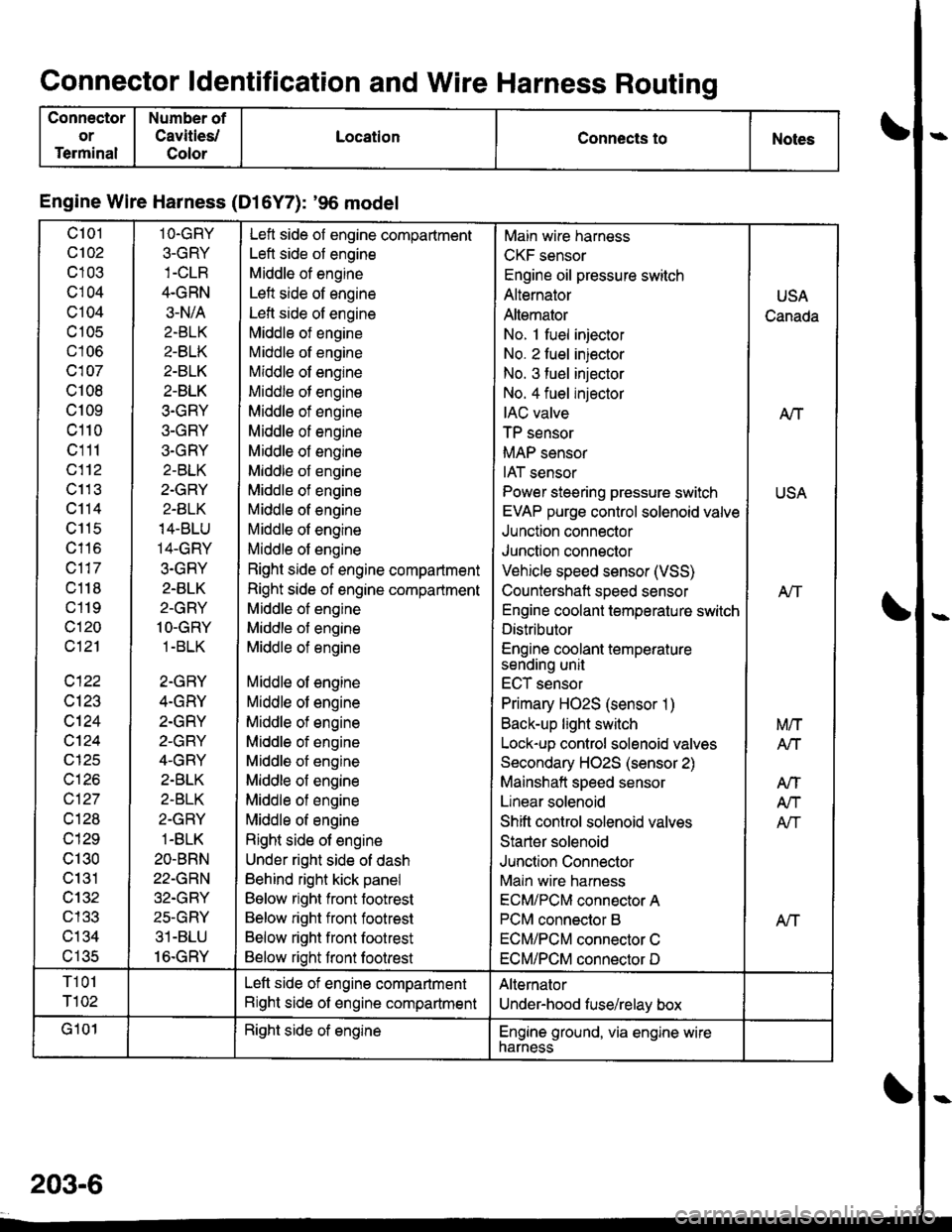
Connector ldentification and Wire Harness Routing
Connector
or
Terminal
Number of
Cavities/
Color
LocationConnects toNotes
Engine Wire Harness (Dl6Y7): '96 model
c101
c102
c103
cl04
c104
c 105
c106
c107
c108
c109
c110
c111
c112
c11 3
c114
c115
c116
c117
c118
c119
c120
c121
c122
c123
c124
cl24
c125
c126
c127
cl28
c129
c130
c131
cl32nl2?
c134al eR
1O.GRY
3-GRY
4.GRN
3-N/A
2.BLK
2-BLK
2-BLK
2-BLK
3.GRY
3-GRY
3.GRY
2-BLK
2.GRY
2-BLK
14-BLU
14-GRY
3.GRY
2.BLK
2-GRY
1O-GRY
1 -BLK
2-GRY
4.GRY
2.GRY
2-GRY
4-GRY
2.BLK
2-BLK
2-GRY
1-BLK
2O-BRN
22-GRN
32.GRY
25-GRY
31-BLU
16.GRY
Left side of engine compartment
Left side of engine
Middle of engine
Left side of engine
Lefl side of engine
Middle of engine
Middle of engine
Middle of engine
Middle of engine
Middle of engine
Middle of engine
Middle of engine
Middle of engine
Middle of engine
Middle of engine
Middle of engine
Middle of engine
Right side of engine compartment
Right side of engine compartment
Middle of engine
Middle of engine
Middle of engine
Middle of engine
Middle of engine
Middle of engine
Middle of engine
Middle of engine
Middle of engine
Middle of engine
Middle of engine
Right side of engine
Under right side of dash
Behind right kick panel
Below right front footrest
Below right front footrest
Below right front footrest
Below right front footrest
Main wire harness
CKF sensor
Engine oil pressure switch
Alternator
Altemator
No. 1 fuel injector
No. 2 fuel injector
No. 3 fuel injector
No. 4 fuel injector
IAC valve
TP sensor
MAP sensor
IAT sensor
Power steering pressure switch
EVAP purge control solenoid valve
Junction connector
Junction connector
Vehicle speed sensor (VSS)
Countershaft speed sensor
Engine coolant temperature switch
Distributor
Engine coolant temperaturesending unit
ECT sensor
Primary HO2S (sensor 1)
Back-up light switch
Lock-up control solenoid valves
Secondary HO2S (sensor 2)
Mainshaft speed sensor
Linear solenoid
Shift control solenoid valves
Starter solenoid
Junction Connector
Main wire harness
ECM/PCM connector A
PCM connector B
ECM/PCM connector C
ECM/PCM connector D
USA
Canada
A/T
USA
Atf
Aff
M/T
Arl
AtT
A/T
Afi
T101
T102
Left side of engine compartment
Right side of engine compartment
Alternator
Under-hood fuse/relay box
G101Right side of englneEngine ground, via engine wirenarness
203-6
Page 2149 of 2189
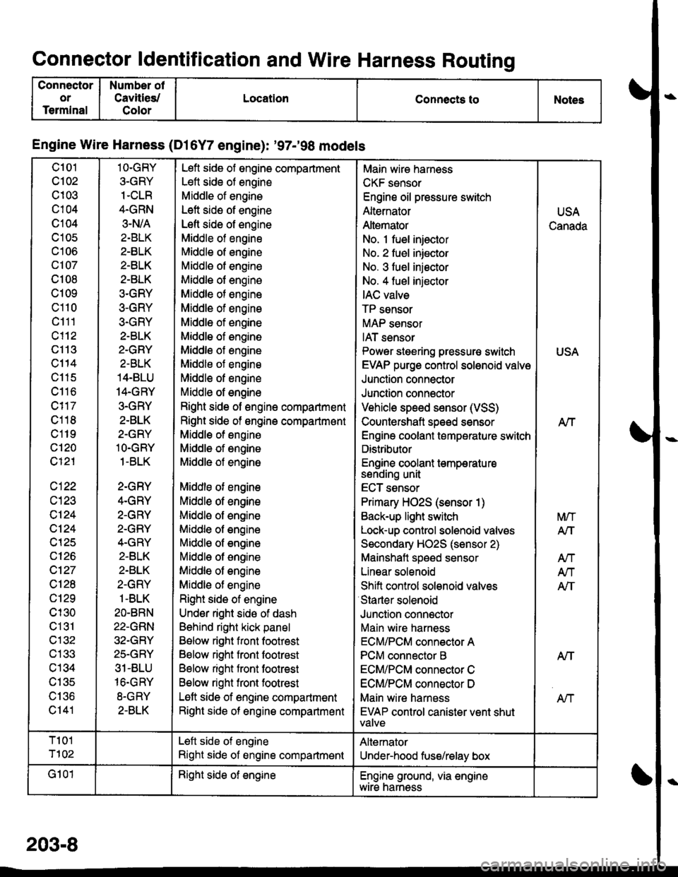
Connector ldentification and Wire Harness Routing
Connector
or
Terminal
Number of
Cavities/
Color
LocationConnects toNoles
Engine Wire Harness (Dl6Y7 engine): '97-'98 models
c101
c102
c103
c104
c104
c105
c106
c107
c108
c109
c110
c111
c113
c114
c115
c116
c118
c119
c'120
c121
c122
c124
c124
c125
c126
c127
c128
c129
cl30
c131
c132
c133
c134
c135
\, | 'tO
c141
1O-GRY
3-GRY
1.CLR
4.GRN
3.N/A
2-BLK
2-BLK
2-BLK
2-BLK
3.GRY
3-GRY
3-GRY
2-BLK
2.GRY
2-BLK
14.BLU
14.GRY
3.GRY
2-BLK
2-GRY
lO.GRY
1-BLK
2-GRY
4.GRY
2.GRY
2-GRY
4.GRY
2.BLK
2.BLK
2-GRY
1-BLK
2O-BRN
22-GRN
32-GRY
25.GRY
31-BLU
16.GRY
8-GRY
2-BLK
Lefl side of engine compartment
Lett side of engine
Middle of engine
Left side of engine
Lefl side of engine
Middle of engine
Middle of engine
Middle of engine
Middle of engine
Middle of engine
Middle of engine
Middle of engine
Middle of engine
Middle of engine
Middle of engine
Middle of engine
Middle of engine
Right side of engine compartment
Right side of ongine compartmont
Middle of engine
Middle of engine
Middle of engine
Middle of engine
Middle of engine
Middle of engine
Middle of engine
Middl€ of engine
Middle of engine
Middle of engine
Middle of engine
Right side of engine
Under right sido of dash
Behind right kick panel
Below right front footrest
Below right front footrest
Below right front footrest
Below right front footrest
Left side of engine compartment
Right side of engine compartmsnt
Main wire hamess
CKF sensor
Engine oil pressure switch
Alternator
Altemator
No. 1 fuel injector
No. 2 fuel iniector
No. 3 fuel iniector
No. 4 fuel injector
IAC valve
TP sensor
MAP sensor
IAT sensor
Power steering pressur€ switch
EVAP purge control solenoid valve
Junction connector
Junction connector
Vehicle speed sensor (VSS)
Countershaft speed sensor
Engine coolant temperature switch
Distributor
Engine coolant temperatu resenorng unI
ECT sensor
Primary HO2S (sensor 1)
Back-up light switch
Lock-up control solenoid valves
Secondary HO2S (sensor 2)
Mainshaft speed sensor
Linear solenoid
Shift conirol solenoid valves
Starter solenoid
Junclion connector
Main wire harness
ECM/PCM connector A
PCM connector B
ECM/PCM connector C
ECM/PCM connsctor D
Main wire harness
EVAP control canister vent shutVAIVE
USA
Canada
USA
Nf
A/T
M/T
A/T
Atl
An
AIT
NT
T101
T102
Left side of engine
Right side of engine compartment
Altemator
Under-hood fuse/relay box
G101Right side of engineEngine ground, via enginewtre narness
203-8
Page 2151 of 2189
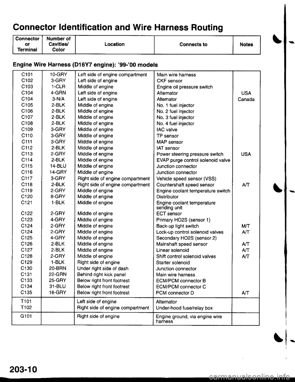
Connector ldentification and Wire Harness Routino
Conneclor
or
Terminal
Number of
Cavities/
Color
LocationConnects toNotes
Engine Wire Harness (Dl6Y7 engine): '99100 models
c101
Q102
c103
c104
c104
c105
UIUO
c107
c108
c109
c110
c111
c112
c113
c114
c11s
c116
c117
c118
c119
c120
c121
c122
c123
c124
cl24
c126
c\27
cl28
cl29
c 130
c131
c'133
c134
v tJc
1O-GRY
3.GRY
1-CLR
4-GRN
3.N/A
2-BLK
2.BTK
2.BLK
2-BLK
3-GRY
3-GRY
3-GRY
2.BLK
2-GRY
2-BLK
14-BLU
14.GRY
3-GRY
2.BLK
2-GRY
8-GRY
1.BLK
2-GRY
4-GRY
2-GRY
2-GRY
4.GRY
2-BLK
2-BLK
2-GRY
1-BLK
2O.BRN
22-GRN
25-GRY
31 -BLU
16-GRY
Left side of engine compartment
Left side of engine
Middle of engine
Left side of engine
Left side of engine
Middle of engine
Middle of engine
Middle of engine
Middle of engine
Middle of engine
Middle of engine
Middle of engine
Middle of engine
Middle ol engine
Middle of engine
Middle of engine
Middle of engine
Right side of engine compartment
Right side of engine compartment
Middle of engine
Middle of engine
Middle of engine
Middle of engine
Middle of engine
Middle of engine
Middle of engine
Middle of engine
Middle of engine
Middle of engine
Middle of engine
Right side of engine
Under right side of dash
Behind right kick panel
Below right front footrest
Below right front footrest
Below right front footrest
Main wire harness
CKF sensor
Engine oil pressure switch
Alternator
Altemator
No. 1 fuel injector
No. 2 fuel injector
No. 3 fuel injector
No. 4 fuel injector
IAC valve
TP sensor
MAP sensor
IAT sensor
Power steering pressure switch
EVAP purge control solenoid valve
Junction connector
Junction connector
Vehicle speed sensor (VSS)
Countershaft speed sensor
Engino coolant temperature switch
Distributor
Engine coolant temperature
sending unit
ECT sensor
Primary HO2S (sensor 1)
Back-up light switch
Lock-up control solenoid valves
Secondary H02S (sensor 2)
Mainshatt speed sensor
Linear solenoid
Shifi control solenoid valves
Starter solenoid
Junction connector
Main wire harness
ECM/PCM connector B
ECM/PCM connector C
PCM connector D
USA
Canada
USA
AIT
Mrl
Atf
AN
A/T
AlT
Afi
T101
r'l02
Left side of engine
Right side of engine compartment
Alternator
Under-hood fuse/relay box
G 101Right side of engineEngine ground, via engine wirenarness
203-10