Data Link Connector 16P HONDA CIVIC 2000 6.G Workshop Manual
[x] Cancel search | Manufacturer: HONDA, Model Year: 2000, Model line: CIVIC, Model: HONDA CIVIC 2000 6.GPages: 2189, PDF Size: 69.39 MB
Page 350 of 2189
Troubleshooting
Troubleshooting Procedures
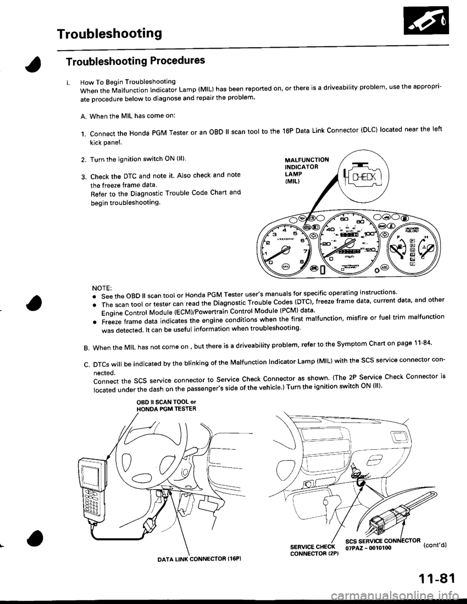
How To Begin Troubleshooting
When the Malfunction Indicator Lamp (MlL) has been reported on, or there is a driveability problem, use the appropr'-
ate orocedure below to diagnose and repair the problem'
A. When the MIL has come on:
,1. connect the Honda PGM Tester or an oBD ll scan tool to the 16P Data Link connector (DLC) located near the left
kick panel.
2. Turn the ignition switch ON (ll)
3. Check the DTC and note it. Also check and note
the freeze trame data
Refer to the Diagnostic Trouble Code Chart and
begin troubleshooting.
NOTE:
.SeetheoBD||scantoolorHondaPGMTesteruser,smanua|sforspecificoperatinginstructions..
.Thescantoo|oltestercanreadtheDiagnosticTroub|ecodes(DTc},freezeframedata,currentdata,andother
Engine Control Module (ECM)/Powertrain Control Module (PCM) data'
oFreezeframedataindicatestheengineconditionswhenthefirstma|function,misfireorfue|trimma|function
was detected. lt can be useful information when troubleshooting'
B. When the MIL has not come on , out there is a d riveability problem, refer to the Symptom Chart on page 1 1-84'
c.DTcswi|lbeindicatedbytheb|inkingoftheMa|function|ndicatorLamp(M|L)withthescsserviceconnectorcon.
nected.
Connect the SCS service connector to Service Check Connector as shown (The 2P Service Check Connector is
|ocatedunderthedashonthepassenger,ssideofthevehic|e')TurntheignitionswitchoN{||)'
OBO ll SCAN TOOL olHONOA PGM TESTER
SERVICE CHECKCONNECTOR I2P)
scs sERvlcE(cont'd)
MALFUNCTIONINDICATORLAMP
DATA LINK CONNECTOR Il6PI
07PAZ - (x)l0100
11-81
Page 726 of 2189
Troubleshootin g Procedures
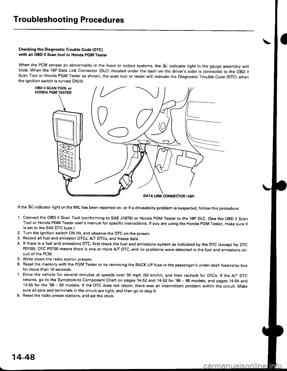
Chccking the Diagnostic Trouble Code IDTC)with an OBD ll Scan tool or Honda PGM Tester
when the PCM senses an abnormality in the input or output systems, the pl indicator light in the gauge assembly willblink. When the 16P Data Link Connector (DLC) (located under the dash on the driver,s side) is connected to the OBD llScan Tool or Honda PGM Tester as shown, the scan tool or tester will indicate the Diagnostic Trouble Code (DTC) whenthe ignition switch is turned ON{ll).
lf the El indicator light or the MIL has been reported on, or lf a driveability problem is suspected, follow this procedure:
1. Connect the OBD ll Scan Tool (conforming to SAE J19781 or Honda PGM Tester to rhe 16p DLC. (See the OBD ll ScanTool or Honda PGM Tester user's manual for specific instructions. lf you are using the Honda PGM Tester, make sure itis set to the SAE DTC type.)
2. Turn the ignition switch ON (lll, and observe the DTC on the screen,3, Record all fuel and emission DTCS, A/T DTCS, and freeze data.4 lf there is a fuel and emissions DTC, first checkthe fuel and emissions system as indicated bythe DTC (except for DTCP0700). DTC P0700 means there is one or more A,/T DTC, and no problems were detected in the fuel and emissions cir-cuit of the PCM.
5. Write down the radio station oresets.
6. Reset the memory with the PGM Tester or by removing the BACK UP fuse in the passenger's under-dash fuse/relay boxfor more than 10 seconds.
7. Drive the vehicle for several minutes at speeds over 30 mph (50 km/hr), and then recheck for DTCS. lf the A"/T DTCreturns, go to the Symptom-to Component Chart on pages 14-52 and 14-53 for'96 - 98 models, and pages 14-54 and14-55 for the'99 - 00 models, lf the DTC does not return, there was an intermittent problem within the circuit. Makesure all pins and terminals in the circuit are tight, and then go to step g.
8. Reset the radio preset stations, and set the clock.
OBD ll SCAN TOOL orHONDA PGM TESTER
DAYA LINK CONNECTOR {16P}
14-44
Page 758 of 2189
Electrical Troubleshooting ('99 - 00 Models)
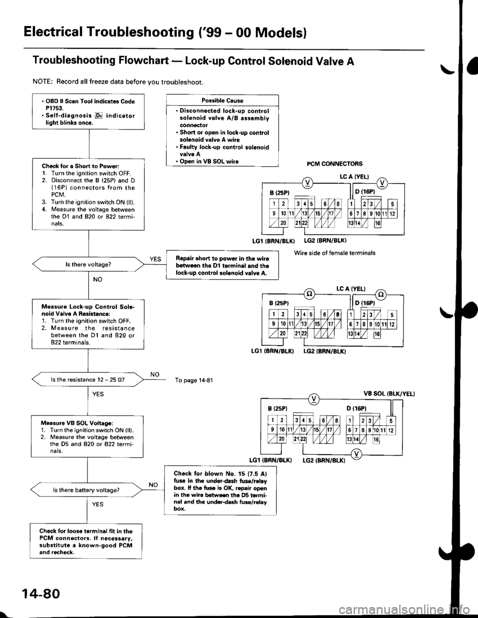
Troubleshooting Flowchart - Lock-up Control Solenoid Valve A
NOTE: Record all freeze data before vou troubleshoot.
Possible Cause
. Disconnocted lock-uD controlsolenoid valve A/B alsemblyconnector. Short or opon in lock-up conkolsolenoid valv6 A wire. Faulty lock-up control solenoidvalva A' Open in VB SOL wireFCM CONNECTORS
LGl IBRN/BLXI LG2 (BRN/BLK)
Wire side ot female terminals
LGl (BRN/BLKILG2 IBRN/8LK)
To page 1+81
a\
. OBD ll Scan Tool indic.t6 CodeP1753.. Self-diagnosis @ indicatorlight blink3 once.
Check lor a Short to Power:L Turn the ignition switch OFF.2. Disconnect the B (25P) and D(16P) connectors lrom thePCt\4.3. Turn the ignition switch ON (ll).4. Measure the voltage betweenthe Dl and 820 or 822 termi-nats.
Ropair short to powcr in the wirebstwoon tho Dl tolminal and thelock-up cor|lrol lolonoid valvo A.
Measu.e Lock-up Cont.ol Sole-noid V.lvo A R63btanc6:1. Turn the ignition switch OFF.2. Measure the resistancebetween the Dl and 820 or822 terminals.
ls the resistance 12 - 25 O?
Measure VB SOL Vohage:1. Turn the ignition switch ON (ll).2. Measure the voltage betweenthe D5 and 820 or 822 termi-nals.
Check for blown No. 15 17.5 Alfu3€ in the undordash fuse/rabybox. l{ th€ tusa ii OK, r.pair oponin the wira b€twoen th€ 05 torfti-nal and thc und€r{ash fuso/r€laybox.
Check to.loose tarminalfit in thePCM connecloa3. ll necessary,substilute a known-good PCMand rocheck.
B (25Pt ll D {16P1
B (2sPt ll D {16P1
I t25Pt D (16P1
l..
14-80
Page 760 of 2189
Electrical Troubleshooting ('99 - 00 Models)
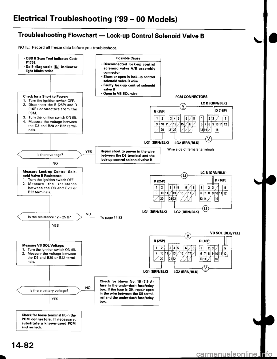
Troubleshooting Flowchart - Lock-up Control Solenoid Valve B
NOTE| Record allfreeze data before you troubleshoot.
Possibla Cause
. Oisconnected lock-uD controlsolenoid velve A/B assemblyconnector. Short or open in lock-up controlsolenoid valv€ B wire. Faulty lock-up control solenoidvalve B' Open in VB SOL wirercM CONNECTORS
To page 14-83
' OBD ll Scan Tool indic.tes CodeP1758.. Self-diagnosis E indicatorlight blinks twice.
Chack for a Short to Power:1. Turn the ignition switch OFF.2. Disconnect the I (25P) and D(16P) connectors from thePCM.3. lurn the ignition switch ON (ll).4. Measure the voltage betweenthe D3 and 820 ot 822 tetmi-nals,
Repair short to power in the wirebetween the D3 terminal and thelock-up contlol solenoid valve B.
Measure Lock-up Control Sole-noid Vdlve I R8i3tance:1. Turn the ignition switch OFF.2, Measure the resistancebetween the D3 and 820 or822 terminals.
ls the resistance 12 - 25 O?
Measure VB SOL Voltago:1. Turn the ignition switch ON lll).2. Measure the voltage betweenthe D5 and 820 or 822 termi-nals.
Check for blown No. 15 {7.5 Alfus€ in the under-dash luse/releybox. It the fuse is OK, repair openin the wir6 between th6 DS terminal and the under-dash fuse/rebyoox,
ls there battery voltage?
Chock for loose te.minal fit in thePCM connectors. It necessary,substitute a known-good PCMend recheck.
B t2sP) ll D t15P)
Wire side ol female terminals
I {2sPt ll D (16Pt
B (25P1 D t16Pt
\
14-82
Page 762 of 2189
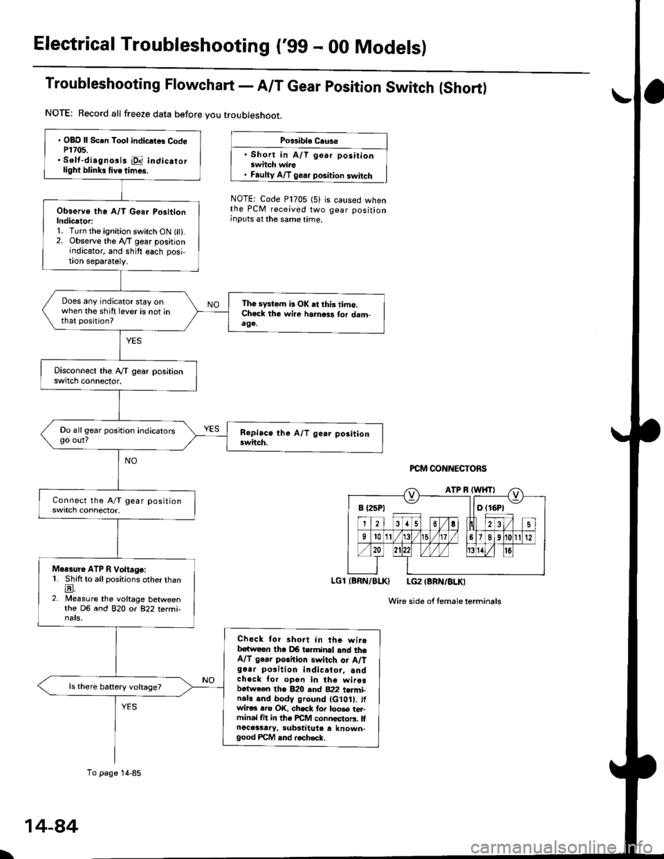
Electrical Troubleshooting ('gg - 00 Models)
Troubleshooting Flowchart - A/T Gear position Switch (Short)
NOTE: Record all freeze data before you troubleshoot.
Po$ible Cause
' Short in A/T go.r positionswhch wire. Faulty A/T goar position switch
NOTE: Code P1705 (5)the PCM received twoinputs at the same time.
is caused whengear position
PCM CONNECTORS
LGl (BRN/BLK) LG2 (BRN/BLKI
Wire side of femaleterminals
B {25P1 llD (16P1
. OBD ll Scan Tool indicrtB CodeP1?05.. Solt-diagno3i3 E indicatorlight blink. tive times.
Observo the A/T Gear PositionIndicetori1. Turn the ignition switch ON fit).2. Observe the lVT gear positionindicator, and shift each posi,!on separately.
Does any indicator stay onwhen the shift lever is not inthat position?
The sFtom is OK at thi3 time.Check the wi.e harness for dam-aga.
Do all gear position indicatorsgo out?
Moasure ATP R Voltage:1. Shift to all positions otherthanE.2. Measure the voltage betweenthe DG and 82O o( 822 terfii-nats.
Check tor short in the wirebatwoen tha DB terminal and theA/T go.r porhion switch or A/Tg6ar po3ition indicator, andchock for opon in the wiresbetween the B20 and B22 t€rmi-n.ls and body ground (G10 . tfwir€c rro OK, chsck fo. loo3e tel-ftinal fit in the FCM connectors. llnoceisary, substiiute e known-good FCM and r€check.
ls there battery voltage?
To page 14-85
\
14-84
Page 765 of 2189
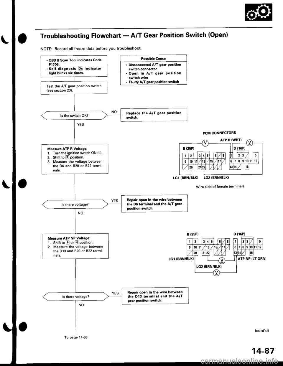
Troubleshooting Flowchart - A/T Gear Position Switch (Open)
NOTE: Record allfreeze data before you troubleshoot.
Po$ible Cause
. Disconnectod A/T goar position
switch conngdor. Open in A/T gear position
switch wire. Fautty Aft gear poshion switch
PCM CONNECTORS
Wire side of lemaleterminals
D (16P1
GRNI
B (25Pt llDtl6Pl
IARN/BLK) LG2IBRN/BLKI
2{6,|235
I't011/t5l/18912
ATP NP (LT
. OBO ll Scan Tool indicatd CodcP1706.' Sslf-diagnosis E indicatorlight blink3 six tim6.
Test the Ay'T gear position switch(see section 23).
Moasure ATP R Volt.ge:'1. Turn the ignition switch ON ('l).
2. Shift to E position.
3. Measure the voltage between
the D6 and 820 ot 822 termi'nals.
Repoir opon in the wire bitween
the D6 torminll and the A/T go.r
position switch.
Measuro ATP NP Volt ge:
1. Shift to E or E position.
2. Measlre the voltage betweenthe D13 and 820 or 822 termi-nals,
Ropair op€n in thc wire betwoonthe D13 terminrl and the A/Tge.r position switch.
LG1 {BBN/BLKI
Io page 14-88
(cont'd)
Page 769 of 2189
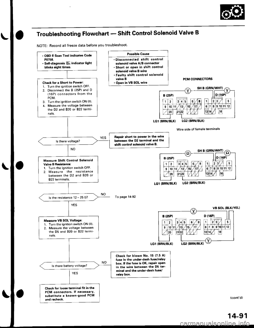
Troubleshooting Flowchart - Shift ControtSolenoid Valve B
NOTE: Record all freeze data before you troubleshoot.
Possiblg Cause
. Disconnectgd ihilt control
solenoid valve A/B conneciotr Short or oDen in shift conlrol
3olgnoid vrlve B wito. Faulty 3hift control solenoid
velve B. Op€n in VB SOL wirercM CONNECTORS
LGlIBRN/BLKI LG2IBRN/BLK)
Wire side of {emale terminals
LGi (BRi|/BLKILG2 IBRN/8LK)
To page 14-92
(cont'd)
14-91
. OBD ll Scan Tool indic.l6 Code
P0758.' Self-diagnosb El indicator light
blinks eighl tim6.
Check tor a Shortto Power:
1. Turn the ignition switch OFF
2. Disconnect the B (25P) and D(16P) connectors from the
PCM.3. Turn the ignition switch ON (lli.
4. Measure the voltage between
the D2 and 820 or 822 termi
nals,
Repaft 3hon to Powor in the wir€
b€tirvoon the D2 termin.l and the
3hift control solenoid valve B.
M€asure Shift Control SolenoidValve B R6isttnce:1. Turn the ignition switch OFF
2. Measure the resistance
between the D2 and 820 or
822 terminals.
ls the resistance 12 - 25 O?
Me.sure VB SOL Vohage:1. Turn the ignition switch ON (ll).
2. Measure the voltage betweenthe D5 and 820 or 822 termi'
nars.
Check lol blown No 15 {7.5 Al
fuse in the under-d.sh luae/rolav
box. ll the fuse is OK, repair open
in ihe wire between tho D5 ter-
minal and the under'dash fus€/relav box.
ls there battery voltage?
Check for loo3e terminal fit in the
PCM connectols. lf necossarY,
substitute a known_good PCM
and rocheck,
B (25Pt - I lD {16P)
B {25P1 D (t6Pl
Page 771 of 2189
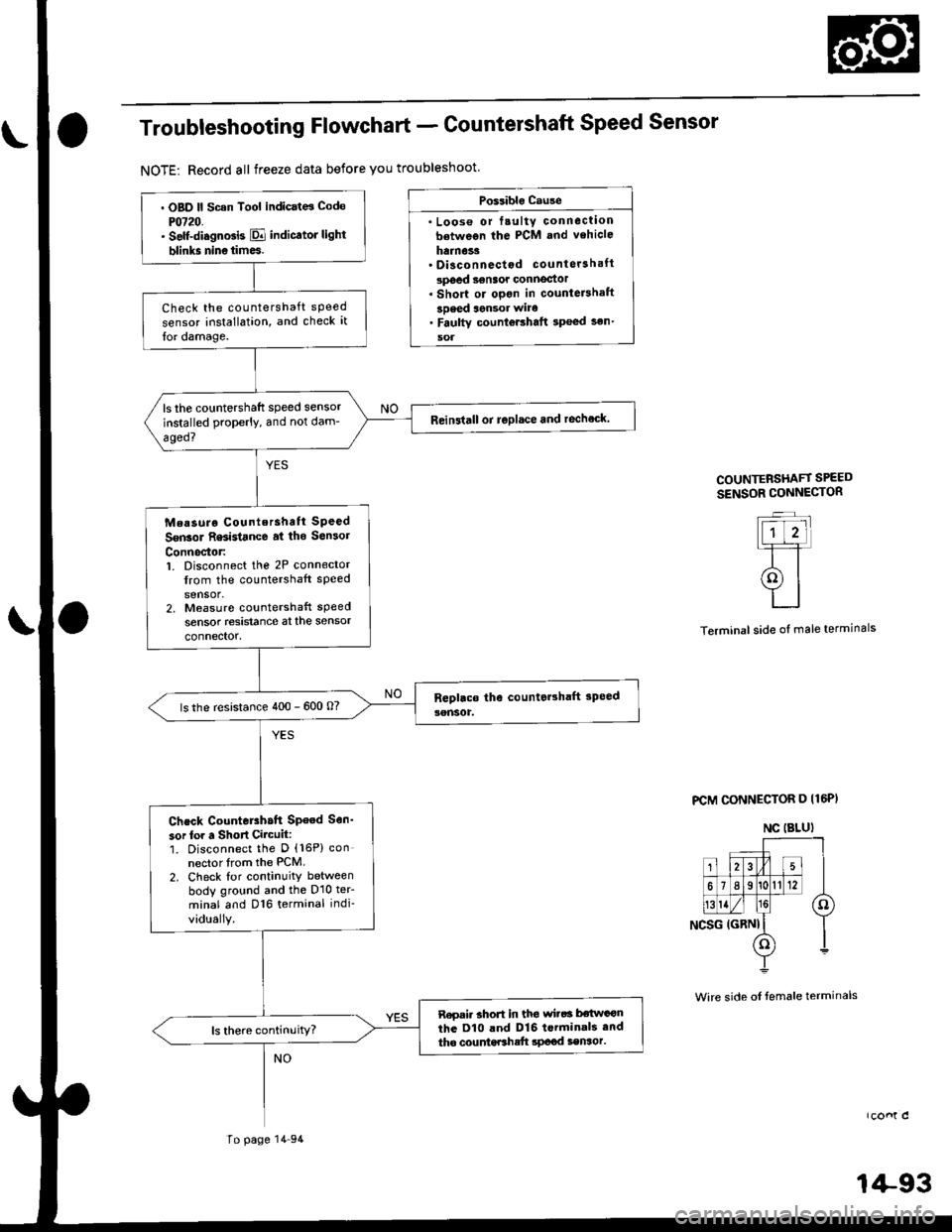
Troubleshooting Flowchart - Countershaft Speed Sensor
NOTE: Record all freeze data before you troubleshoot
Po$iblo Cause
. Loos€ or fsulty conneclionbetween the PCM and vehicle
hainoss' Disconnectod countersh.ft
spoed senaof connoctor. Short or opgn in counteBhaft
3Deed aensor wire. Faulty counloEhaft 3p€ed sen'
soa
COUNTERSHAFf SPEED
SENSOR CONNESTOR
Terminal side oI male terminals
FCM CONNECTOR D I16PI
rconl c
1+93
NC IBLUI
. OBD ll Scan Tool indicat6 Code
PO720.. Self-diagnosis E indicator light
blinks nin6times.
Check the countershaft sPeed
sensor installation, and check it
lor damage.
ls the countershaft speed sensor
installed properly, and not dam-
aged?
Reinstall or replace and rechock.
Measurg Counlershatt SPeed
Sgn3ol R6istance at tho Son3ol
Connector:1. Disconnect the 2P connector
from the countershaft sPeed
sensor.2, Measuro countershaft sPeed
sensor resistanca at the sensor
connector.
ls the resistance 400 - 600 O?
Chcck CounteEh.tt SPeed Sen'
sor lor a Short Circuit:1. Disconnect the D {16P) con
nector trom the PCM.2. Check lor continuity between
body ground and the D10 ter_
minal and D16 terminal indi-
vid!ally.
R6oai. short in tl|€ wi.6a bstwa€n
the D10 and D16 t.rminali end
tho countdthatt rP€od senaor.
To page 14 94
Wire side of temale terminals
Page 911 of 2189
Troubleshooting Procedures
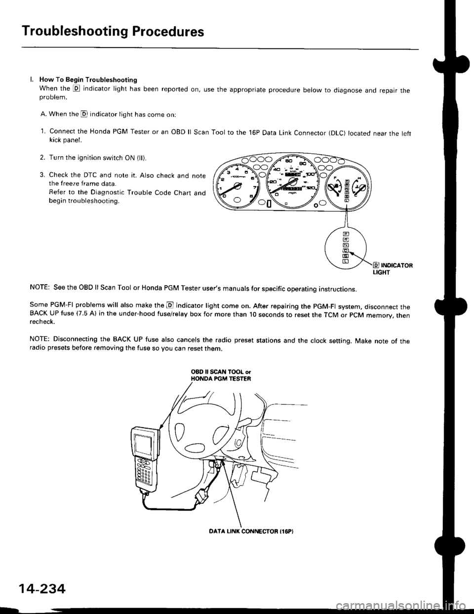
l. How To Begin Troubleshooting
When the E indicator light has been reported on, use the appropriate procedure below to diagnose and repatr theproDlem.
A. When the @ indicator light has come on:
l connect the Honda PGM Tester or an oBD ll Scan Tool to the 16P Data Link Connector (DLc) located near the leftkick panel.
Turn the ignition switch ON (ll).
Check the DTC and note it. Also check and notethe freeze frame data.
Refer to the Diagnostic Trouble Code Chart andbegin troubleshooting.
INOICATORLIGHT
NOTE: SeetheOBDll Scan Tool or Honda PGM Tester user's manuals for specific operating instructions.
Some PGM-FI problems will also make the E indicator light come on. After repairing the pGM-Fl system, disconnect theBACK UP fuse (7.5 Al in the under-hood fuse/relay box for more than l0 seconds to reset the TCM or PCM memory, rnenrecheck.
NOTE: Disconnecting the BACK UP fuse also cancels the radio preset stations and the clock setting. Make note of theradio presets before removing the fuse so you can reset them,
2.
3.
o0\e--loo
OATA LINK CONNECTOB I16P}
14-234
Page 914 of 2189
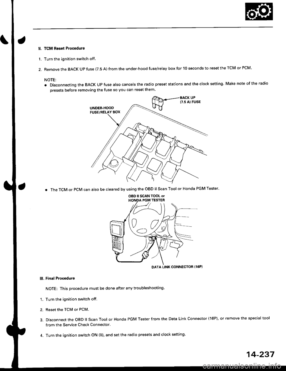
ll. TCM Reset Plocedure
1. Turn the ignition switch off.
2. Remove the BACK Up fuse (7.5 A) from the under-hood fuse/relay box for 10 seconds to reset the TCM or PCM.
NOTE:
. Disconnecting the BACK UPfuse also cancelsthe radio preset stations and the clock setting Make nole ofthe radio
presets before removing the fuse so you can reset them
BACK UPt7.s Al FusE
. The TCM or PCM can also be cleared by using the OBD ll Scan Tool or Honda PGM Tester'
DATA LINK CONNECTOR {16PI
lll. Final Procedut€
NOTE: This procedure must be done after any troubleshooting
'1. Turn the ignition switch off.
2. Reset the TcM or PCM.
3. Disconnect the OBD ll Scan Tool or Honda PGM Tester from the Data Link Connector (16P), or remove the special tool
from the Service Check Connector.
4. Turn the ignition switch ON (ll), and set the radio presets and clock setting.
OBD ll SCAN TOOL o.PGM TESTER
14-237