Interlock HONDA CIVIC 2000 6.G Workshop Manual
[x] Cancel search | Manufacturer: HONDA, Model Year: 2000, Model line: CIVIC, Model: HONDA CIVIC 2000 6.GPages: 2189, PDF Size: 69.39 MB
Page 55 of 2189
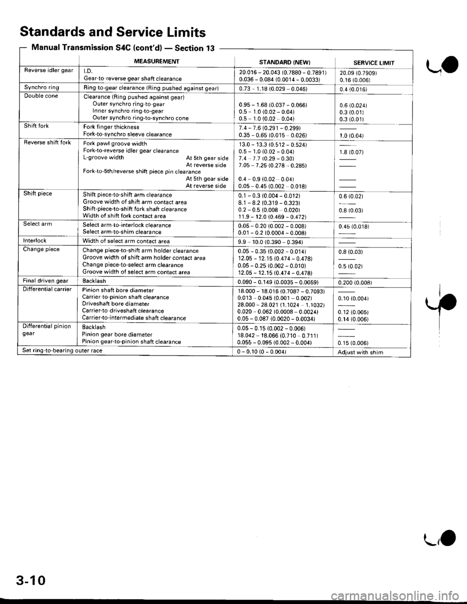
MEASUREMENTSTANDARD (NEW) SERVICE LIMITReverse idler geart.D.Gear-to reverse gear shaft clearance20.016 - 20.043 (0.7880 -0.7891)
0.036 - 0.084 {0.0014 - 0.0033)20.09 (0.7909)
0.16 (0.006)
Synchro ringRing to-gear clearance (Ring pushed against gear)0.73 - 1.18 (0.029 0.046)0.4 (0.016)Double coneClearance (Ring pushed against geadOuter synchro ring to gearIn ner synchro ring to-gearOuter synchro ring-to-synchro cone
0.9s - 1.68 10.037 - 0.066)0.5 - 1.0 (0.02 - 0.04)0.5 1.0 (0.02 - 0.04)
0.6 (0.024)
0.3 {0.01)0.3 (0.01)Shift forkFork {inger thicknessFork-to synchro sleeve clearance7.4 - 7.6 (0.291- 0.299i0.35 - 0.65 (0.015 0.026)1.0 (0.04)Beverse shift forkFork pawl groove widthFork-to-reverse idler gear clearanceL-groove width At 5th gear sideAt reverse sideFork'to-5th/reverse shift piece pin clearanceAt 5th gear sideAt reverse side
13.0 - 13.3 10.512 - 0.524)0.5 - 1.0 (0.02 - 0.04)7.4 t.1 10.29 -O.30)
7 .O5 - 7 .25 (0.21A - 0.2A5i'
0.4 0.9 (0.02 0.04)0.05 0.45 (0.002 - 0.018)
1€ {0.07)
Shift pieceShift piece-to-shift arm clearanceGroove width of shift arm contact areaShilt'piece-to-shift fork shaft clearanceWidth of shift lork contact area
0.1 - 0.3 (0.004 - 0.012)8.1-8.2 (0.319 - 0.323i0.2 - 0.5 (0.008 0.020)1 1.9 - 12.0 10.469 - 0.472)
0.6 (0.02)
0.8 (0.03)
Select armSelect arm-to-interlock clearanceSelect arm to-shim clearance0.05 - 0.20 (0.002 - 0.008)0.01 - 0.2 10.0004 - 0.008)0.45 (0.018)
InterlockWidth of select arm contact area9.9 - 10.0 (0.390 0.394)Change pieceChange piece-to-shilt arm holder clearanceGroove width ot shitt arm holder contact areaChange piece-to select arm clearanceGroove width of select arm contact area
0.05 - 0.35 (0.002 - 0.014)12.05 - 12.15 \0.474 -0.47a1
0.05 - 0.25 (0.002 - 0.010)12.05 - 12. t5 (0.474 - 0.478)
0.8 {0.03)
0.5 (0.02)
Final driven gearBacklash0.090 - 0.149 (0.0035 - 0.0059)0.200 (0.008)DifferentialcarrierPinion shatt bore diameterCarrier to-pinion shaft clearanceDriveshaft bore diameterCarrier-to driveshaft clearanceCarrier-to-int6rmediate shatt clearance
18.000 - 18.016 10.7087 - 0.7093)0.013 - 0.045 {0.001 0.002)24.000 - 28.021 11.1024 1.1032)0.020,0.062 (0.0008 - 0.0024)0.05 - 0.087 {0.0020 - 0.0034)
0.10 {0.004)
0.12 (0.005)
0.14 (0.006)
Differential piniongearBacklashPinion gear bore diameterPinion gear-to-pinion shaft clearance
0.05 -0.15 (0.002 - 0.006)18.042 18.066 (0.710 - 0.711)0.055 - 0.095 (0.002 - 0.004)0.15 (0.006)
Set ring to bearing outer race0 - 0.10 (0 - 0.004)Adjust with shim
Standards and
Manual Transmission
Service
S4C (cont'd)
Limits
- Section 13
ua
.'1'
3-10
L,O
Page 310 of 2189
-'
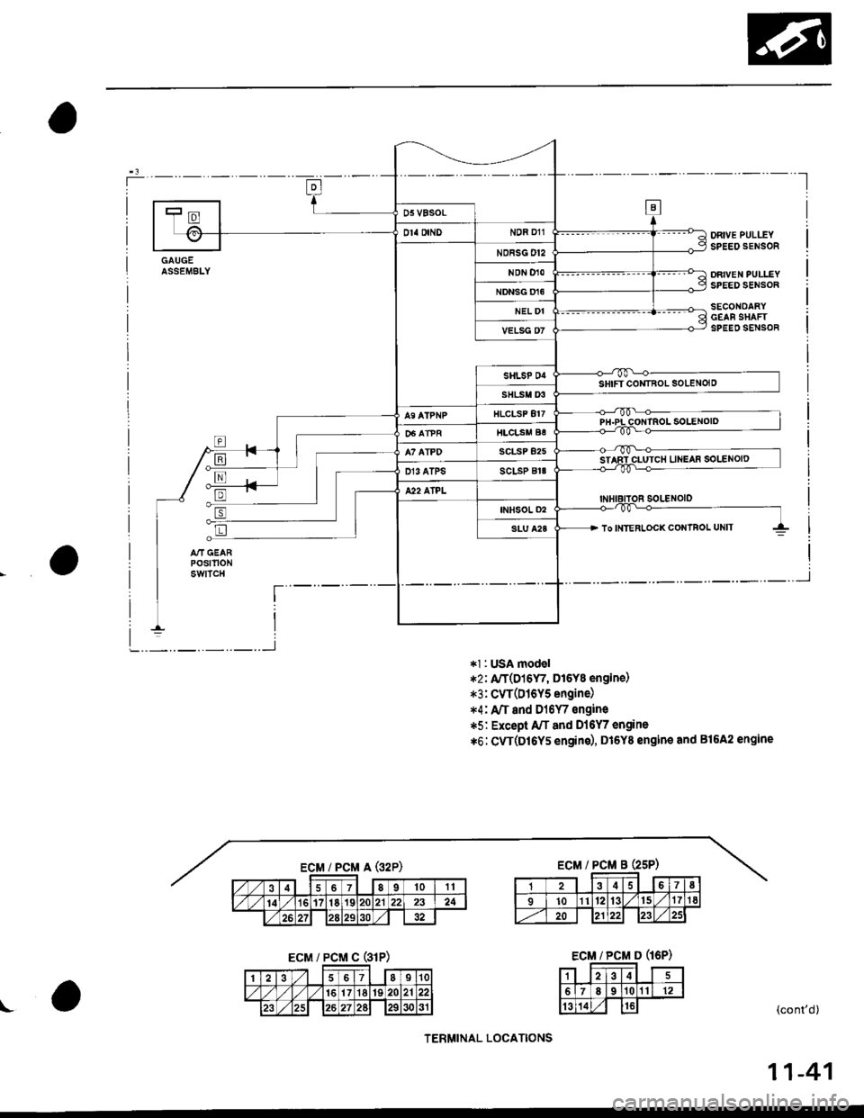
GAUGEASSEMALY
DRIVE PULLEYSPEED SENSOR
ORIVEN PULLEYSPEED SENSOR
SECONOARYGEAB SHAFTSPEED SENSOR
SOLENOID
To INTERLOCK CONIBOL UNIT
*l : USA model
*2: a/T(D16Y/, D16Y8 engine)
,.3: CW(016Y5 engine)
*4: A/T and D16W engine
*5: Except A/T and Dl5Y7 engine
*6: Cw(Dl6Y5 engine), Dl5Y8 engine and 816A2 engine
(cont'd)
11-41
EcM/PcMA(32P)EcM/PcMB(25P)
7II1011
t41617181920121222324
ECM/PCMC(31P)ECM/PCMD(I6P)
I
TERMINAL LOCATIONS
Page 358 of 2189
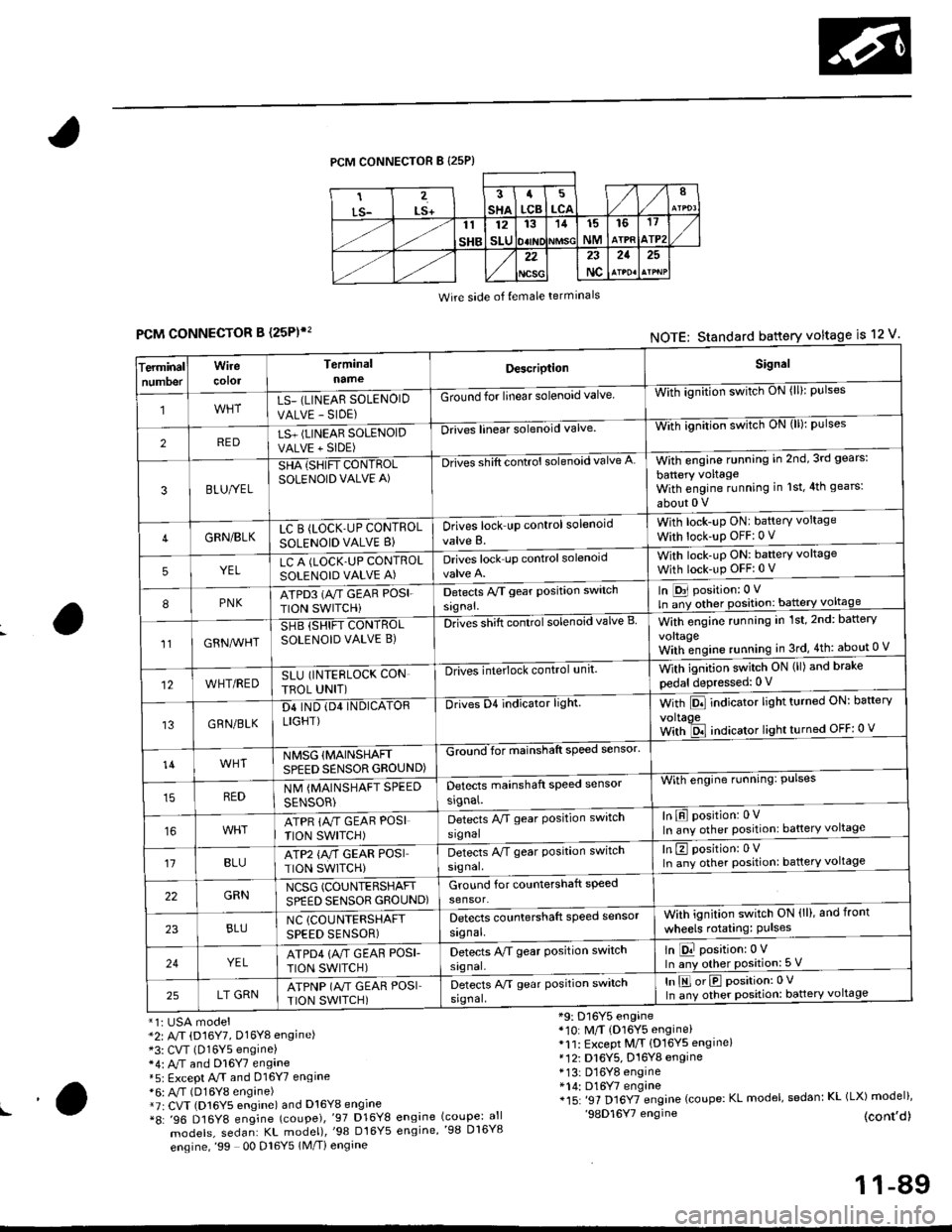
PCM CONNECTOR B {25P)
Wire side of {emale terminals
CONNECTOR B (25P)',
*1i USA model*2: A/T (D16Y7, Dl6Yg engine)*3: CVT (D16Y5 engine)*4: M and Dl6Y7 engane*5: Except A.rT and 016Y7 engine*6: A,/T (D16Y8 engine)*7r CVT (D16Y5 engine) and D16Y8 engine*8: '96 D16Y8 engine (coupe),'97 D16Y8
models, sedan: KL model),'98 Dt6Y5
engine,'99 00 Dl6Y5 1M/Ti engine
*9: D16Y5 engine*10: M/T (D16Y5 engine)*11: Except M/T {D16YS engine}*12i D16Y5, D16Y8 engine* 13: D16Y8 engine*14: D16Y7 engine*15: '97 Dl6YTengine (coupe: KL model, sedan: KL (LX) model)''98D16Y7 engine (cont,d)engine (coupe: allengine,'98 D16Y8
FCMNOTE: Standard battery voltage is 12 v'
erminalTnumoer
Wirecotol
TerminalnameDescriptionSignal
1LS_ (LINEAR SOLENOID
VALVE - SIDE)
Ground for linear solenoid valveWii-ignnion switctr oN {ll}: pulses
2REDLS+ (LINEAR SOLENOIDVALVE + SIDE)
-Drii6l linear solenoid valveWith ignilion switch uN (lll: pulses
3BLU/YEL
SHA {SHIFT CONTROLSOLENOID VALVE A)
-Drives shift control solenoid valve AWith engine running in 2nd,3rd gears:
battery voltageWith engine running in 1st,4th gears:
about 0 V
4GRN/BLKLC B (LOCK'UP CONTROL
SOLENOID VALVE B}Drives lock up control solenoid
valve B.
With lock-up ONI battery voltage
With lock-up OFF:0 v
5YELLC A (LOCK.UP CONTROLSOLENOID VALVE A)Drives lock up controlsolenoidWith lock-uP ON: baftery voltage
With lock-up OFFi 0 V
8PNKATPD3 (NT GEAR POSI.
TION SWITCHi
Detects Py'T gear Position switch
signal.
In [D31 position: 0 V
ln ;y other position: battery voltage
1lGRN^lr'HT
SHB (SHIFT CONTROLSOLENOID VALVE B)DnGs shift conttol solenoid valve BWith engine running in 1st,2nd: battery
vo|taqeWith;ngine running in 3rd,4th: about 0 V
12WHT/REDSLU (INTERLOCK CON
TBOL UNIT)
-DlivEilite'lock control,rnit.With ignition switch ON (ll) and brake
pedal depressed: 0 V
13GRN/BLK
D4 IND (D4 INDICATORLIGHT)
Drives D4 indicator light.With Pll indicator lrght turneo urr: oarterv
voltaoeWith ld indicator light turned OFF: 0 v
14WHTNMSG {MAINSHAFTSPEED SENSOR GROUND)
GZiiI'for mainshaft speed sensol
With engine running: Pulses
In E position: 0VIn any other position: battery voltage
REDNM {MAINSHAFT SPEED
SENSOR)
Detects mainshaft speed sensor
srgnal.
ATPR {M GEAR POSI
TION SWITCH)
Detects M gear Position switch
signal
't1BLUATP2 {A/T GEAR POSITION SWITCH)
Detects A/T gear Position switch
signal.
In E position: 0VIn any other position: battery voltage
22GRNNCSG (COUNTERSHAFT
SPEED SENSOR GROUND)Ground for countershaft speed
sensor.
23BLUNC (COUNTERSHAFT
SPEED SENSOR)
Detects countershaft speed sensor
signal.
Vvith ignition switch ON (ll), and front
wheels rotating: Pulses
24YELATPD4 {M GEAF POSI-
TION SWITCH)
Detects M gear Position switch
signal.
ln E position:0 VIn any other position: 5 V
25LT GRNATPNP (A"/T GEAR POSITION SWITCH)
Detects A/T gear Position switch
srgnal,
In E orE position:0 V
In any other position: battery voltage
!a
11-89
Page 361 of 2189
Troubleshooting
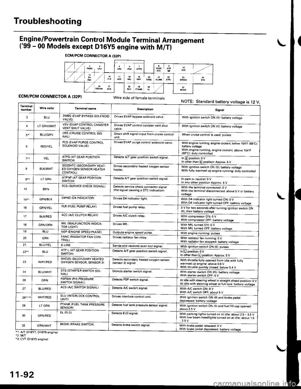
Engine/P_o,wertrain Control Module Terminal Arrangement('99 - 00 Models except Dl6Y5 engine with M/Tl
ECM/PCM CONNECTOR A (32P)Wire side ot temale terminalsNOTE:Standard battery voltage is l2 V
ECM/PCM CONNECTOR A I32PI
Sign!l
3BLU2WSS (EVAP 8YPAsS SOLENOIDDrives EVAP bypass solenoid vatve,With gn'tion swnch ON (lll banery votlage
LT GRN/I/VIITVSV {EVAP CONTNOL CANISTERVENTSHUTVALVE]Drives EVAP controt ca n isrer v€nt shutWilh ignilion switch ON {tl): b€ttery vottage
8LU/GNNC8S (CRUISE CONTSOL SIGOown shift signal inpot lrom c.uise conrrolWhen crurss control is used:purses
68ED/YELPCS {EVAP PURGE CONTROLSOTENOIOVALVE)Drives EVAP purge conrrol sotenoid vatve.With engine running, engine cootant, betow r54.F (6a,C):
With engine.unning, €ngine coolant, abov€ 154.F(68'C): duty conlrolled
YELATPD {AT GEAR POSITIONSWITCH)ootects A/T gear posnion swilch s,gnar.In otherthan @ posilion: Apprcx. 5 V
8BLK,IflHTSO2SHTC (SECONDARY HEATED OXYGEN SENSOS HEATEFCONTFOL)
Drives sscondary h€ared oxygen senso.Wilh isn,rion swirch ON (ll):banery votraseWith lully warm6d dp€ngire runn'ng:dury controled
LT GRNATPNP (AT GEAF POSITIONSWITCH)oereds A/T 9€a r position switch signat.In Parr or neulrsl:0 VIn anyother position approx.5 v
t088NSCS (SERVICE CHECK SIGNAL)Oetects ssruice check connecror signal(the signalcausing a OTC indication)with rh€ t6rminal connected: 0 vWith the rerm ina I disconneded: abour 5 V of ban€ry
GNN/BIKD4IND (D4INDICATON]Drives Oa indicaio. lighr.With D4 indicator lightturned ON: O VWith D4 indicator lightturned OFF: battery vo ttageG8N/YETFTF (FUEL PUI\,4P SELAY)Orivos tuel pump relay,0V for two s€conds lfrer turnrng rgnilior swtcn ON(ll), then batt€ry voltage11BTI(REDACC (Al/C CTUTCH SELAY)Drives A./C clutch reray.With compressor ON:O VWilh comp.ssor OFF; battery vottage18GFN/OFNMI! (A,IAIFUNCTION INDICA.TOF LIGHT)With MlLturned ON:0 VWith l\,llL tornod OFF|batrery votrsge198tuNEP (ENGINE SPEED PUTSEIOulputs6ngine speed pulse,Wilh engin6.unning: putses
20GFNFANC {SADIATOR FAN CONTnoL)Orives radiarortan relay.Wirh r.distor t6n running:OVWith radiatortan stopped: banery vottage21ELUA/ELK LINESends and r€ceives s.an lool signal.With ignition switch ON (ll):p!ts€s
22'lBLUATP L {AT GEAS POSITIONswtTcH)Oelocis A"/T gear posirion switch siSnat.In othfflhan E position: Apprcx. 5 V
23SHO25 (SECONOARY HEATEDOXYCEN SENSOR, SENSOF 2)Detects secondsry hoar€d oxygen sensorWith lhronle f! lly or'6ned from idte with fu ywarmod up engine: above 0.6 vWiih th.onl6 quickb, closd:below 0,4 V24STS ISTAFTEN SWITCH SIGDebcrs staner switch signat.Wirh srarterswitch ON (tttJ: batteryvottogeWith sraftsr cwirch OFF:0 V26GFNPSPSW iPlS PNESSURESWITCII SIGNAL)Derecrs PSP switch signat.Atidle with steoring wheolin srraightahead position: O VAt idl6with steering wheetal fult lock: barery vo ttags27BLU/REOACS (AJC SWITCH SIGNALJOer*ts ,ay'C swirch signat.Wiih ty'C switch ON;0VWilh Ay'C switch OFF|aboor 5VWHT/REDSLU iINTERLOCK CONTROIUNIT)Drivos interloct control unit.With ignltion switch ON (ll)and brake pedaldepresed: batlory volrage29LT GRNPTANK (FUEL TANK PFESSUEESENSOR)Oer6ds lu€l tank pr€ssura sonsor signat.Wilh ig.rrrd swirch ON rttr and fuetti
cap ooen6d.
30GRN/FEOEr (ELOIWith parking lighlsrurned on ar idteiaboui 2.5- 3.S VWirh low beam he€dlig hts turnqd on ai idts: aboul 1.52.5 V32GRN/'WHTAKSW (BFAKE SWITCH)Detets brak€ swrtch signEt,With brake pedal r6l€ased:0 VWhh brake pedaldepres*d: battery voltEse'1:A./T (D16Y7, D16Y8 engine)*2: rvt/T13: CVT (D16Y5 engine)
11-92
Page 571 of 2189
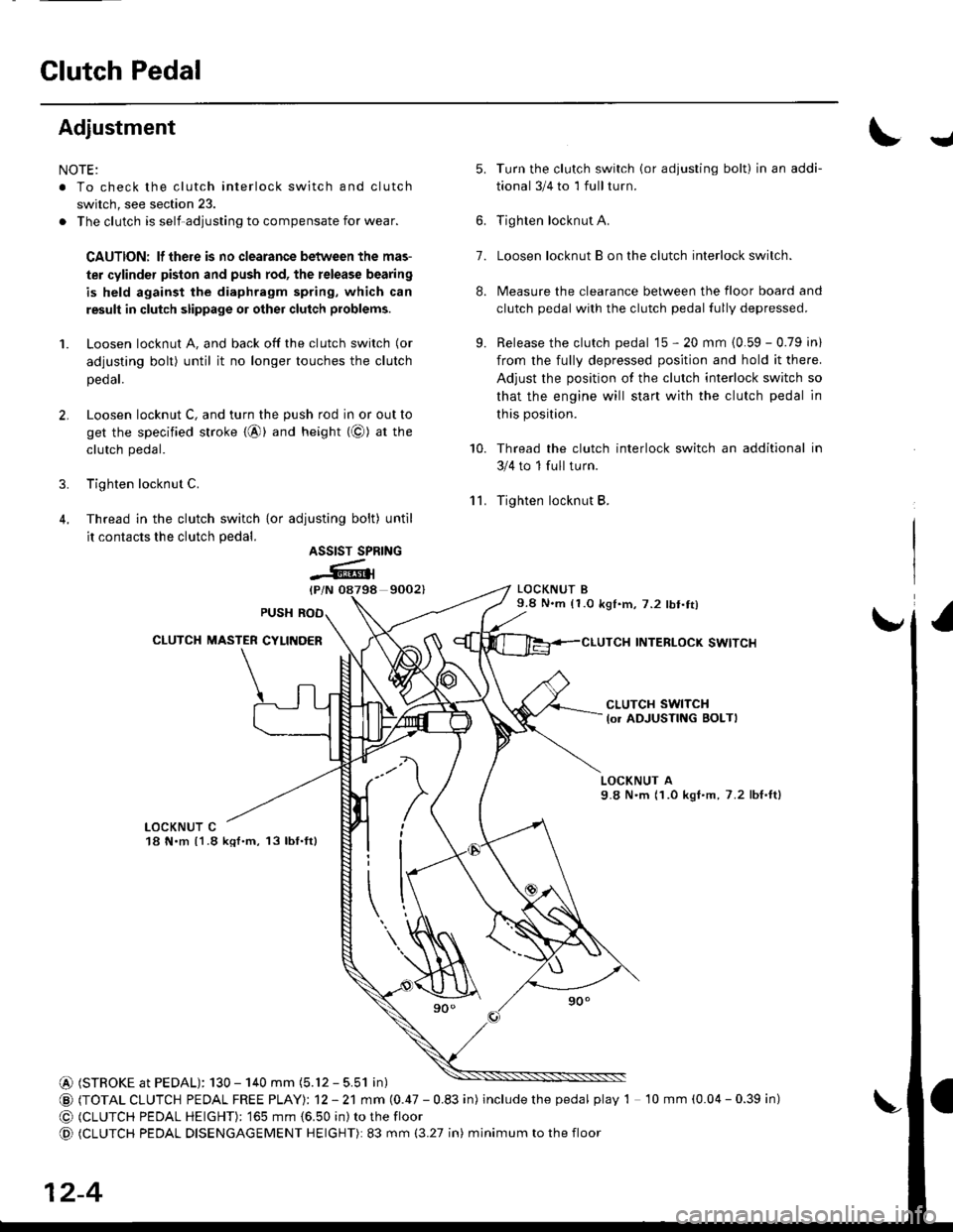
Glutch Pedal
Adjustment
NOTE:
. To check the clutch interlock switch and clutch
switch, see section 23.
. The clutch is self-adjusting to compensate for wear.
CAUTION: lf there is no clearance between the mas-
ter cylinder pislon and push rod, the release bearing
is held against the diaphragm spring, which can
result in clutch slippage 01 other clutch problems.
1. Loosen locknut A, and back off the clutch switch (or
adjusting bolt) until it no longer touches the clutch
peoar.
2. Loosen locknut C, and turn the push rod in or out to
get the specified stroke {@} and height (@) at tne
clutch pedal.
3. Tighten locknut C.
4. Thread in the clutch switch {or adiusting bolt) until
it contacts the clutch pedal.
9002)
Turn the clutch switch (or adjusting bolt) in an addi-
tional 3/4 to 1 full turn.
Tighten locknut A.
Loosen locknut B on the clutch interlock switch.
Measure the clearance between the floor board and
clutch pedal with the clutch pedal fully depressed.
Release the clutch pedal 15 - 20 mm {0.59 - 0.79 in)
from the fully depressed position and hold it there.
Adjust the position of the clutch interlock switch so
that the engine will start with the clutch pedal in
this position.
Thread the clutch interlock switch an additional in
3/4 to 1 full turn.
Tighten locknut B.
LOCKNUT B9.8 N.m (1.0 k91.m,7.2 lbt.tt)
INTERLOCK SWITCI{
J
'lL
5.
7.
8.
9.
10.
ASSIST SPRING
-Atl
CLUTCH SWITCH
lo. ADJUSTING BOLTI
LOCKNUT A9.8 N'm (1.0 kgI.m, 7.2 lbf,ft)
LOCKNUT C18 N.m {1.8 kql.m, 13lbf.ft}
@ (STROKE at PEDAL): 130 - 140 mm (5.12 - 5.51 in)
@ (TOTAL CLUTCH PEDAL FREE PTAYI: 12 - 21 mm (0.47 - 0.83 in) includethepedal play 1 10 mm (0.04 - 0.39 in)
@ (CLUTCH PEDAL HEIGHT): '�]65 mm {6.50 in) to the floor
@ (CLUTCH PEDAL DISENGAGEMENT HEIGHT): 83 mm (3.27 in) minimum to the floor
12-4
Page 591 of 2189
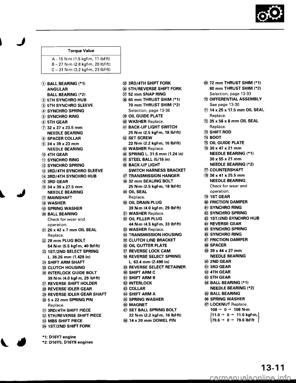
Torque Value
A - 15 N.m (1.5 kgf.m, 1'1 lbf.ft)
B - 27 N.m (2.8 kgf.m. 20 lbift)
C - 31 N.m {3.2 kgnm, 23 lbift)
\
O BALL BEARING (*T)
ANGULAR
BALL BEARING {*2I
O 5TH SYNCHRO HUB
O 5TH SYNCHRO SLEEVE
€) SYNCHRO SPRING
o SYNCHRO B|NG
@ 5TH GEAR
@ gz xgt x 23.5 mm
NEEDLE BEARING
@ SPACER COLLAR
@34x39x23mm
NEEDLE BEARING
(D 4TH GEAR
O SYNCHRO RING
C) SYNCHRO SPRING
CO 3RD/4TH SYNCHRO SLEEVE
@ 3RD/4TH SYNCHRO HUB
(} 3RD GEAR
@34x39x27.5mmNEEDLE BEARING
G) MAINSHAFT
G) WASHER
@ SPRING WASHER
@ BALL BEARING
Check for wear and
operation.(E 26x42x7 mm OIL SEAL
Replace.
@ 28 mm PLUG BOLT
5,1 N.m {5.5 kgf'm, /t0 lbt'ft)
@ lsT/zND SELECT SPRING
L. 36.26 mm (1./P8 in)
@ SHIFT ARM SHAFT
@ CLUTCH HOUSING
@ INTEELOCK GUIDE BOLT
39 N.m (4.0 kgf.m, 29 lbf.ftl
@ REVERSE SHIFT HOLDER
@ REVERSE IDLER GEAR
@ REVERSE IDLER GEAR SHAFT
@ 5 x 22 mm SPRING PIN
Replace.
@ 3RD/4TH SHIFT PIECE
@ 5TH/REVERSE SHIFT PIECE
@ MBS SHIFT PIECE
@ 1ST/2ND SHIFI FORK
*1:D16Y7 engine*2: D16Y5, D16Y8 engines
@ 3RD//|TH SHIFT FORK
@ 5TH/REVERSE SHIFT FORK
@ 52 mm SNAP RING
@ 65 mm THRUST SHIM (*11
70 mm THRUST SHIM (*21
Selection, page 13-36
@ OIL GUIDE PLATE
@ wASHER Replace.
@ BACK.UP LIGHT SWITCH
25 N.m (2.5 kgf'm, 18 lbf'ft)
@ sET SCREW
22 N.m {2.2 kgf.m, 16 lbl.ft}
@ WASHER Replace.
@D SPRING 1.31.6 mm (1.2,1inl
@ STEEL BALL 15/16 in)
@ BACK-UP LIGHT
SWITCH HARNESS BRACKET
@ TRANSMISSION HANGER
@ 32 MM SEALING BOLT
25 N.m (2.5 kgf.m, 18 lbt'ft)
@ OIL SEAL
Replace.
@ OIL DRAIN PLUG
39 N.m (4.0 kgf.m, 29 lbf.ft)
@ WASHER Replace.
@} OIL FILLER PLUG
44 N.m (4.5 kgf.m, 33 lbf'ftl
@ WASHER Replace.
@) TRANSMISSION HOUSING
€) CLUTCH LINE BRACKET
@ OIL GUTTER PLATE
@ REVERSE LOCK CAM
@ REVEBSE SELECT SPRING
L. 63.4 mm {2.,196 in)
@ REVERSE SELECT RETAINER
@ SHIFT ARM C
@ SHIFT ARM B
@ INTERLoCK
@ COLLAR
@ SHIFT ARM A
@ SPRING WASHER
@ MAGNET
@ sET BALL SPRING BOLT
22 N.m (2.2 kgf.m, 16 lbf.ftl
@ 14 x 20 mm DOWEL PIN
@ 72 mm THRUST SHIM l*11
80 mm THRUST SHIM (*21
Selection, page '13-33
@ DIFFERENTIAL ASSEMBLY
See page 13-30
@ 14 x 25 x 17.5 mm OIL SEAL
Replace.
@ 35 x 56 x 8 mm OIL SEAL
Replace.
@ SHIFT ROD
@ BOOr
@ OIL GUIDE PLATE
@30x47x21 mm
NEEDLE BEARING (* 1}
30x55x21 mm
NEEDLE BEARING {'2)
@ COUNTERSHAFT
@36x41 x 25.5 mm
NEEDLE BEARING
Check for wear and
operatron.
@ lsT GEAR
@ FRICTION DAMPER
@ SYNCHRO RING
@ SYNCHRO SPRTNG
@ lST/2ND SYNCHRO HUB
@ REVERSE GEAR
@ SYNCHRO SPRING
@ SYNCHRO RING
@ FRICTION DAMPER
@ SPACER
@39x4lx27mm
NEEDLE BEARING
@ 2ND GEAR
@ 3RD GEAR
@ 4TH GEAR
@ sTH GEAR
@) BALL BEARING {* 1}
NEEDLE BEARING (*2}
@ BALL BEARING
@) SPRING WASHER
@ LoCKNUT Replace.
108 - 0- 108 N.m
ftt.o* o- 1r.o kst.m,l
179.6- 0- 79.6 rbtft I
13-1 1
Page 594 of 2189
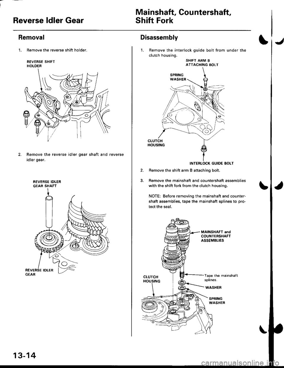
Reverse ldler Gear
Mainshaft, Cou ntershaft,
Shift Fork
Removal
1. Remove the reverse shift holder.
REVERSE SHIFTHOLOER
Remove the reverse id ler
idler gear.
gear shaft and reverse
REVERSE IDLERGEAR SHAFT
13-14
Disassembly
1. Remove the interlock guide bolt from under the
clutch housing.
SHIFT ARM 8ATTACHING BOLT
CLUTCHHOUSING
INTERLOCK GUIDE BOLT
Remove the shift arm B attaching bolt.
Remove the mainshaft and countershaft assemblies
with the shift fork from the clutch housinq.
NOTE: Before removing the mainshaft and counter-
shaft assemblies, tape the mainshaft splines to pro-
tect the seal.
Tape the mainshaftsplines.
WASHER
SPRINGWASHER
Page 609 of 2189
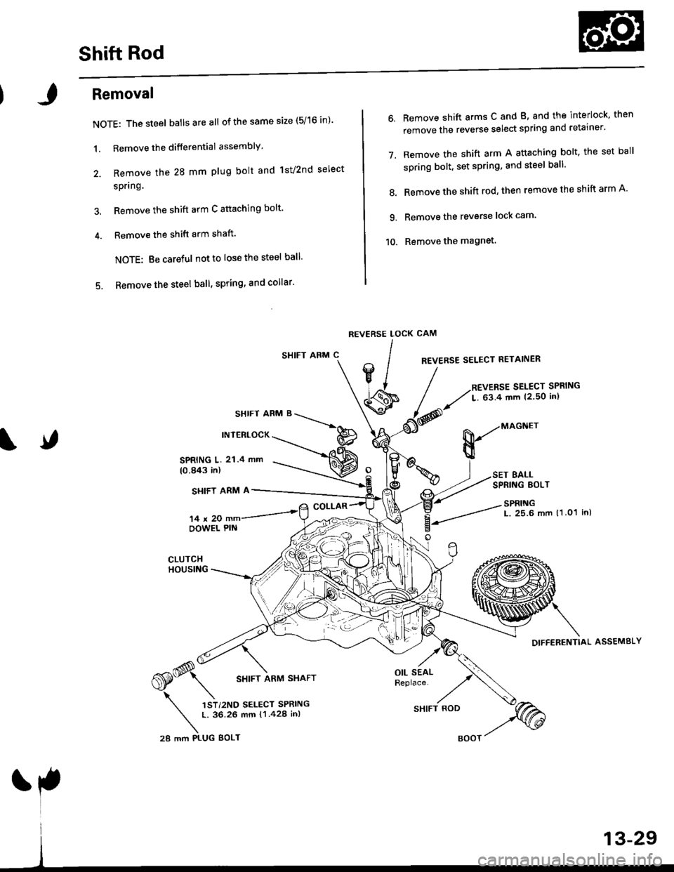
Shift Rod
Removal
NOTE: The steel batlsareall of the same size (5/16 in)'
1. Remove the differential assembly'
2. Remove the 28 mm plug bolt and lst/2nd select
spring.
3. Remove the shift arm C attaching bolt'
4. Remove the shift arm shaft'
NOTE: Be careful notto lose the steel ball'
5. Remove the steel ball, spring, and collar'
SHIFT ARM C
SHIFT ARM B
INTERLOCK
6. Remove shift arms C and B, and the interlock, then
remove the reverse select spring and retainer'
7. Remove the shift arm A attaching bolt, the set ball
spring bolt, set spring, and steel ball'
8. Remove the shift rod' then remove the shift arm A'
9. Remove the reverse lock cam'
10. Remove the magnet.
CAM
REVERSE SELECT RETAINER
REVERSE SELECT SPRING
L. 63.4 mm {2.50 inl
REVERSE LOCK
lIV/
' lJ
\s
SPRING L. 21.4 mm(0.843 in)
SI{IFT ARM A
14x20OOWEL PIN
COLLAR
,*(S* \
6S* srtrr ran,t srarr
\
',)r,r"o r..."r "rr,*n
t. 36.26 mm {1.428 in,
28 mm PI-UG BOLT
OIL SEALReplace.
&-"onn"
BALLSPRING EOLT
SPRINGL. 25.6 mm 11.01 inl
DIFFERENTIAL ASSEMBLY
SHIFT ROD
Page 619 of 2189
Transmission
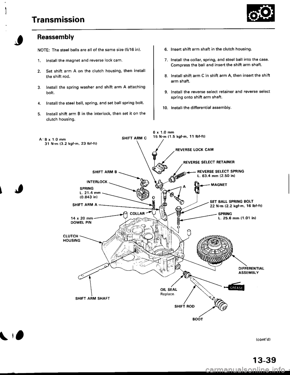
Reassembly
NOTE: The steel balls are all ofthe same size (5/16 in).
1. Install the magnet and reverse lock cam.
2. Set shift arm A on the clutch housing, then install
the shift rod.
3. Install the spring washer and shift arm A attaching
bolt.
Installthe steel ball, spring, and set ball spring bolt.
Install shift arm B in the interlock, then set it on the
clutch housing.
1.
Insert shift arm shaft in the clutch housing.
Install the collar, spring. and steel ball into the case.
Compress the ball and insert the shift arm shaft,
Install shift arm C in shift arm A, then insert the shift
arm shaft.
Install the reverse select retainer and reverse select
spring onto shift arm shaft.
Install the differential assembly.
5.
8.
9.
10.
A:8x1.0mm3'l N,m (3.2 kgt.m,23 lbf.ft)
6 x 1.0 mm15 N.m 11.5 kgt.m, 11 lbt'ftl
OIL SEALReplace.
SI{IFT ARM C
COLLAR
REVERSE SELECT SPRINGL. 63.4 mm 12.50 in)
REVERSE LOCK CAM
REVERSE SELECT RETAINER
sHtFT ARM ' ___\.*^
rNrERLocK p
|Jiiill---=l@
MAGNET
SET BALL SPRING BOLT22 N.m 12.2 kgl.m, 16 lbf'ftl
SPRINGL. 25.6 mm (1.O1 in)
SHIFT AFM A
CLUTCHHOUSING
SHIFT ARM SHAFT
(cont'd)
13-39
SHIFT ROD
l
BOOT
Page 620 of 2189
Transmission
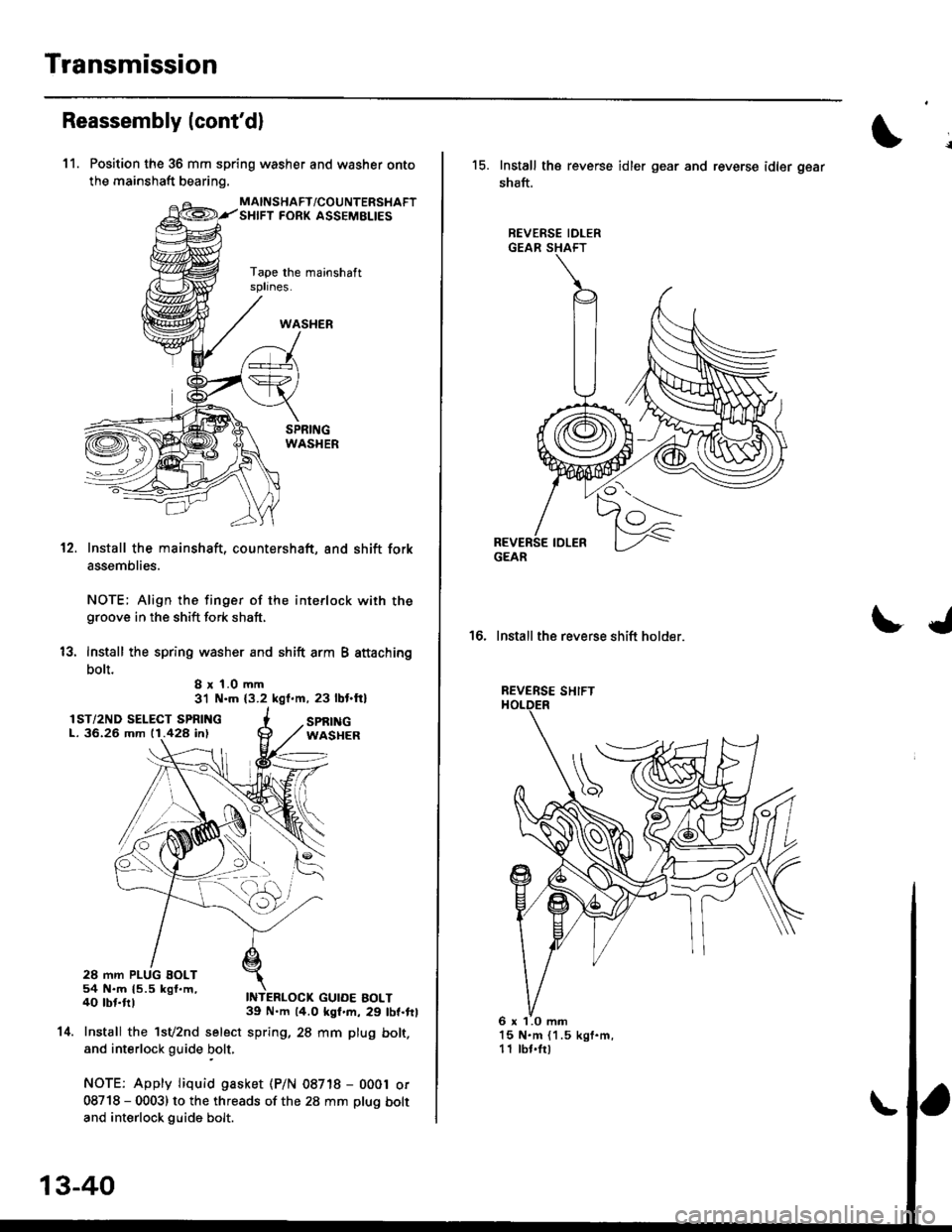
Reassembly lcont'dl
11. Position the 36 mm spring washer and washer onto
the mainshaft bearing.
MAINSHAFT/COUNTERSHAFTSHIFT FORK ASSEMELIES
Tape the mainshaftsplines.
12.
13.
Install the mainshaft, countershaft, and shift fork
assemblies.
NOTE; Align the finger of the interlock with thegroove in the shift fork shaft,
lnstall the spring washer and shift arm B attaching
bolt.I x 1.0 mm31 N.m (3.2 kgl.m, 23 lbt.ft)
IST/2ND SELECT SPRINGL. 36.26 mm 11.428 in)
54 N.m 15.5 kgf.m,40 tbt.ftl
SPf,INGWASHER
GUIDE BOLT
14.
39 N.m 14.0 kgf.m, 29 lbf.frl
Install the 1sv2nd select spring, 28 mm plug bolt.
and interlock guide bolt,
NOTE: Apply Iiquid gasket (P/N 08718 - 0001 or
08718 - 0003) to the threads of the 28 mm plug bolt
and interlock guide bolt.
13-40
15. Install the reverse idler gear and reverse idler gear
shaft.
REVERSE IDLERGEAR SHAFT
LJ16. Install the reverse shift holder.
REVERSE SHIFT
l5 N.m (1.5 kgf.m,11 lbt.trl
GEAR
6 x 1.0 mm