LMA HONDA CIVIC 2000 6.G Workshop Manual
[x] Cancel search | Manufacturer: HONDA, Model Year: 2000, Model line: CIVIC, Model: HONDA CIVIC 2000 6.GPages: 2189, PDF Size: 69.39 MB
Page 39 of 2189
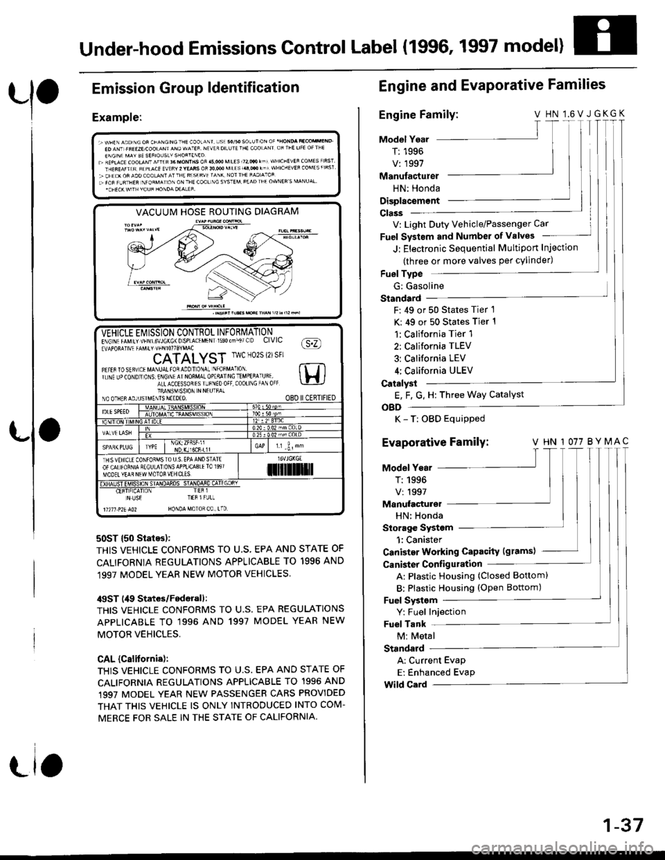
Under-hood Emissions Control Label (1996, 1997 model)
Emission
Example:
Group ldentification
VACUUM HOSE ROUTING DIAGRAM
50ST {50 States):
THIS VEHICLE CONFORMS TO U.S, EPA AND STATE OF
CALIFORNIA REGULATIONS APPLICABLE TO 1996 AND
1997 MODEL YEAR NEW MOTOR VEHICLES.
/$ST (49 States/Federall:
THIS VEHICLE CONFORMS TO U.S. EPA REGULATIONS
APPLICABLE TO '1996 AND 1997 MODEL YEAR NEW
MOTOB VEHICLES,
CAL (Calitornis):
THIS VEHICLE CONFORMS TO U.S. EPA AND STATE OF
CALIFORNIA REGULATIONS APPLICABLE TO 1996 AND,1997 MODEL YEAR NEW PASSENGER CARS PROVIDED
THAT THIS VEHICLE IS ONLY INTROOUCED INTO COM-
MERCE FOR SALE IN THE STATE OF CALIFORNIA.
-VEHICLE Ei/ ISSION CONTROL INFORMATIONE\G\. rrMrr vtsNrs\JLK6\Dsp-A(.MFN 590(--,. O CIVIC fa:n!APOF!]V4 -AV.t' !-rirorrSrMAc \Y:/
CATALYST IwcN02S{2)sFr
Fl.tarostq! tMA\uAttoaaooTo\a- \'oFM^ ro rt Tlr. \F Jo(O\D ' O\S E\Gr\l AINOnMA-OolqllNCTMoEqA Uql lH ia-LACCESSoT rS r-F\Eo0F C00ll\G -A 0( \-!-lJTRANSM1SSION N NEUTFAINO OTHERAOJUSIMENTS NEEDEO. O8D IICERTIFIED
IDLESPEEOATDC
NDr(Jl6CR.L1lr.r -i, "
TH SVEH CLE CONfOFMSTO U S. EPA AND STATEOF CALfORNIA RECULAI ONSAPPLICA8IElO 1997MOOET YEAR NEW MOTOR VEH CL'Silil]]lrl
Er!4#_"E!!ifl 4q!sq+HT-q4E!rL
N US€ TIEB l FULL
11211 .?2E AO2 HONDA MoTOR C0 , tTD
Engine and EvaPorative Families
Engine Family:V HN l.6VJGKGK
Model Year
T: 1996
V: 1997
T I
T|I
Manufacturer
HN: Honda
Displacem€nt
V: Light Duty Vehicle/Passenger Car
Fuel Systsm and Number of valves
J: Electronic Sequential Multiport Injection
(three or more valves per cylinder)
Fuel Type
G: Gasoline
Standard
F: 49 or 50 States Tier 1
K: 49 or 50 States Tier 1
1:California Tier 1
2: California TLEV
3: California LEV
4; California ULEV
Catalyst
E, F, G. H: Three Way Catalyst
OBD
K - T: OBD Equipped
Evaporative Family: v HN 1077 BYMAc'|T
Model Year
T:1996 |V:1997 lManufacturel
HN: Honda
Storage System
1:Canister
Canister Working Capacity (grams)
Canister Configulation
A: Plastic Housing (Closed Bottom)
B: Plastic Housing (oPen Bottom)
Fuel Systsm
Y: Fuel Injection
Fuel Tank
M: Metal
Standard
A: Current Evap
E: Enhanced Evap
Wild Card
1-37
Page 41 of 2189

(1999 modell
Emission Group ldentification
Example:
VEHICLE EMISSION CONTROL INFOEMATION
13 S VEH CLE CONFORMS IO U S EAPPL CABLETO I999 MOOELYEAR NEW PASSENCER
CATALYST
IAIV€ L{SHCOLDSPARTPLU6CAPEv
@oHONDA MOTOECO LTD
FEDERAL TIER 1:
THIS VEHICLE CONFORMS TO U.S, EPA REGULATIONS
APPLICABLE TO '1999 MODEL YEAR NEW PASSENGER
CARS.
CALIFORNIA + NLEV {RESTRICTEDI TLEV:
THIS VEHICLE CONFORIVIS TO CALIFORNIA REGULA-
TIONS APPLICABLE TO 1999 MODEL YEAR NEW TLEV
PASSENGER CARS AND TO U.S. EPA NLEV PROGRAM
REGULATIONS APPLICABLE TO 1999 NEW TLEV PAS-
SENGER CARS.
THIS VEHICLE MAY ONLY BE INTRODUCED INTO COM-
MERCE FOR SALE IN CALIFORNIA, A STATE THAT HAS
THE CALIFORNIA STANDARDS IN EFFECT TO WHICH
THIS VEHICLE HAS BEEN CERTIFIED, A STATE THAT
HAS OPTED INTO THE NLEV PROGRAM, OR A STATE
CONTIGUOUS THERETO.
50 STATE LEV + CFFV + NLEV {UNRESTRICTED}:
THIS VEHICLE CONFORMS TO U.S. EPA NLEV AND
CLEAN-FUEL VEHICLE AND CALIFORNIA REGULA'
TIONS APPLICABLE TO GASOLINE FUELED 1999
MODEL YEAR NEW LEV IPASSENGER CARS/LIGHT
DUW TRUCKS].
50 STATE TLEV + NLEV (UNRESTRICTED):
THIS VEHICLE CONFORMS TO U.S. EPA NLEV REGULA'
TIONS APPLICABLE TO 1999 MODEL YEAR NEW TLEV
PASSENGER CARS AND CALIFORNIA REGULATIONS
APPLICABLE TO 1999 MODEL YEAR NEW TLEV IPAS'
SENGER CARS/LIGHT DUW TRUCKS].
Engine and Evaporative Families
Engine Family:
Model Yeal
X:1999
X
T
JF1
T
AAD_T
Manutacturer
HNX: Honda
Tvpe
V: Light Duty Vehicle/Passenger Car
Disolacement
Sequence Characters
Type
R: ORVR
Canister Work CaPacitY (gramsl
Sequence Characters
Evaporative FamilY: + +
ModelYearIX:1999 lManufacturer
HNX: Honda
0090
T_
R
HNX V
rT
rl
0 t.6
1-39
Page 44 of 2189
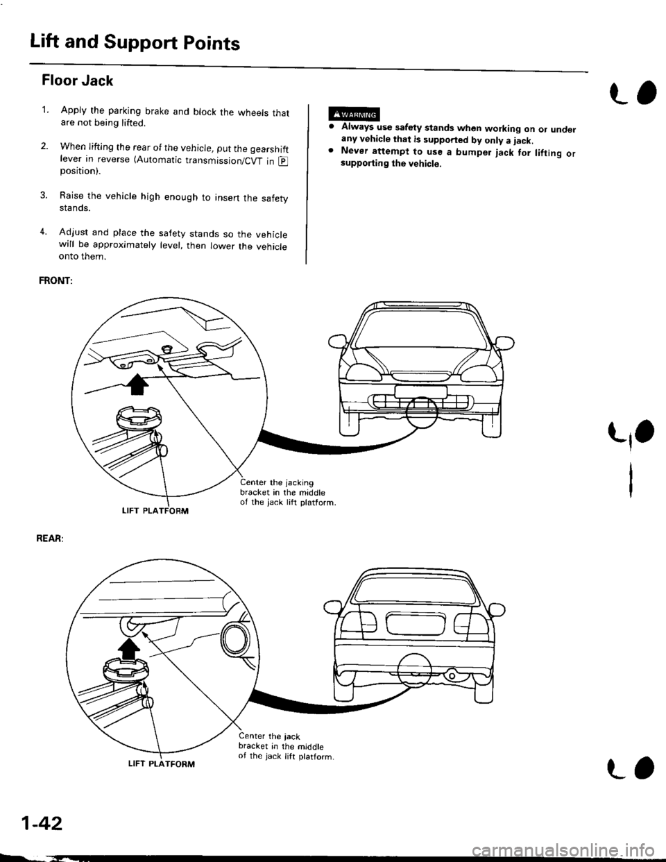
Lift and Support Points
Floor Jack
Apply the parking brake and block the wheets thatare not being lifted.
When lifting the rear of the vehicle, put the gearshiftlever in reverse (Automatic transmission/Cw in Eposition).
Raise the vehicle high enough to insert the safetystands.
Adjust and place the safety stands so the vehiclewill be approxlmately level, then lower the vehicleonto them.
FRONT:
Always use safety stands whon working on or undelany vehicle that is supported by only a iack.Never attempt to use a bumper jack for lifting orsupporting the vehicle.
t,1.
REAR:
1-42
LIFT PLA
4.
Center the jacking
bracket in the middleof the iack lift platform.
Center the iackbracket in the middleof the jack lift ptatform.
-,-_
LIFT PLATFORM
L,
Page 56 of 2189
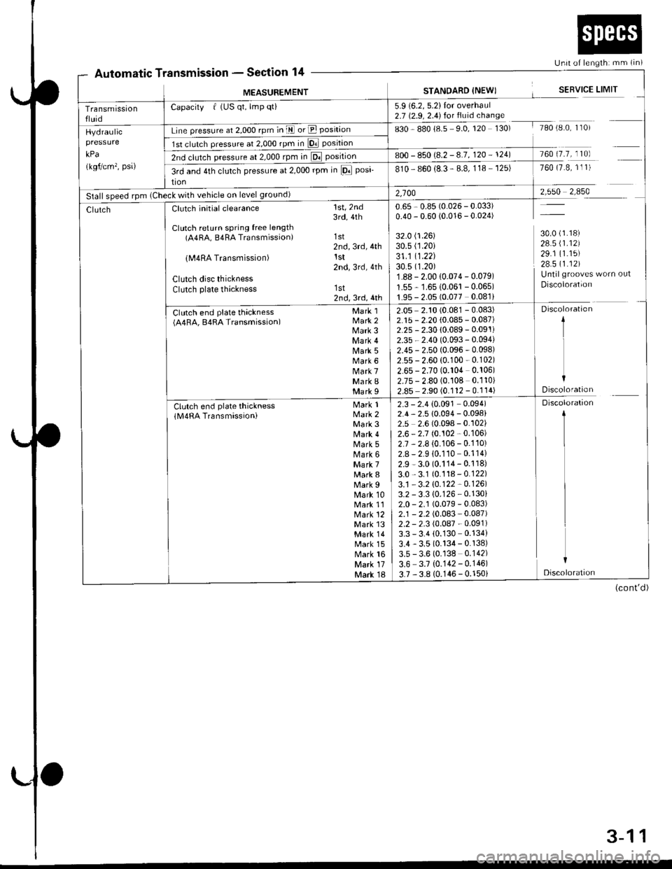
Automatic TtssronSection 14Unit of lengthi mm (in)
fansmtssron -
MEASUREMENTSTANOARD {NEWISERVICE LIMIT
Transmissionfluid
Capacity f (US qt, lmp qti5.9 (6.2, 5.2)Ior overhaul2.7 (2.9, 2.4) for fluid chanse
sgO g8ol85 SO,rzO rSO, rAo,e'0 I 0,Hydraulic
kPa
(kgf/cm', psa)
Line pressure at 2,000 rpm in E or E position
1st clulch pressure al 2,O0Orpmin D. position
2nd clutch pressure at 2,000 rpm in El position800 - 850 (8.2 -8.7, 120 - 124)760 (7.7, 110)
3rd and 4th clutch pressure at 2,000 rpm in lFl posi-
tion
810- 860 (8.3 - 8.8, 118 - 125)760 (7.8, 1l 1)
Stall speed rpm (Check with vehicle on level ground)2,10028 1_ ffi9
30.0 (1.18)
28.5 \1.12)29.1 (1.15)
28.511.121Untilgrooves worn out
Discoloration
ClutchClutch initial clearance
Clutch return spring free length(A4RA, B4RA Transmission)
lM4RA Transmission)
Clutch disc thicknessClutch plate thickness
Ctr t"h ""d pl"t" thl"t**(A4RA, B4RA Transmission)
1st,2nd3rd,4th
1st2nd,3rd,4thlst2nd,3rd,4th
1st2nd,3rd,4th
Mark 1Mark 2Mark 3Mark 4Mark 5Mark 6Mark 7Mark IMark I
M"*lMark 2Mark 3Mark 4Mark 5Mark 6Mark 7Mark 8Mark 9Mark 10Mark 11Mark 12Mark l3Mark 14Mark 15Mark 16Mark 17Mark 18
Clutch end plate thickness(M4RA Transmassioni
0.65 , 0.85 (0.026 - 0.033)0.40 - 0.60 (0.016 - 0.024)
32.0 (1.26)
30.s (1.20i
31 .1 11.22130.5 (1.20)
1.88 - 2.00 {0.074 - 0.079)
1.55 - 1.6510.061 -0.065)
1.95 - 2.05 (0.077 0.081)
2.05 2.10 (0.081 - 0.083)2.15 - 2.20 (0.085 - 0.087)2.25 - 2.30 {0.089 - 0.091i
2.35 - 2.40 (0.093 - 0.094)
2.45 - 2.50 (0.096 - 0.098)2.55 - 2.60 (0.100 - 0.102)
2.65 - 2.70 (0.104 0.106)2.75 - 2.80 (0.108 0.110)
2.85 2.90 (0.112 - 0.114)
Discoloration
1
I
IDiscoloration
2.3 - 2.4 {0.091 0.094)2.4, 2.5 {0.094 - 0.098)2.5 2.6 (0.098 - 0.102)2.6 - 2.7 (0.102 - 0.106)
2.7 , 2.8 (0.106 - 0.110)2.8 - 2.9 10.110 0.114)
2.9 - 3.0 (0.114- 0.118)
3.0,3.1 (0.118-0.122)
3.1 - 3.2 \O.122 -0.1261
3.2 - 3.3 {0.126 - 0.130}2.0 - 2.1 (0.079 - 0.083)2.1 - 2.2 (0.083 - 0.087)2.2 - 2.3 (0.087 - 0.091)3.3 - 3.4 (0.130 0.134)
3.4 - 3.5 (0.134 - 0.138)3.5 - 3.6 (0.138 0.142)
3.6 3.7 {0.142- 0.146)
3.7 ,3.8 10.146 - 0.150i
Discoloration
1
I
I
L
I
Discoloration
(cont'd)
3-11
Page 66 of 2189
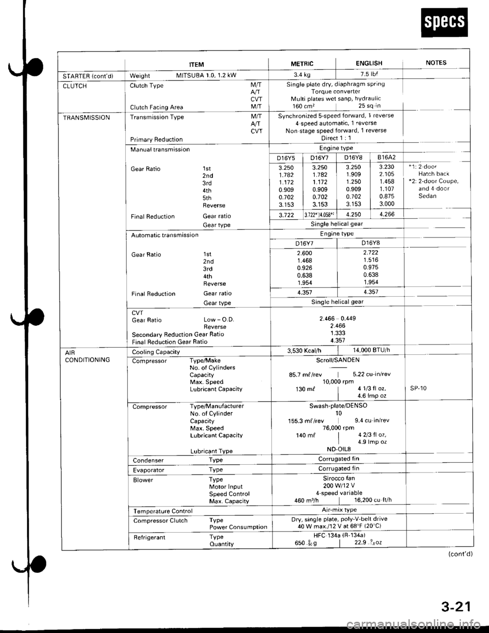
trEM I merntc ENGLISH NorEs
SfAnff n i*nt-i- W"'gf,t MllSUBA r.u, l.z kw r'4 rg
CLUTCHClutch Type
Clutch Facing Area
M/T
CVTM/T
Single plate dry, diaphragm springTorque converterMulti plates wet sanP, hYdraulic160 cm,25 sq in
Synchronized 5-speed forward, 1 reverse
4 speed automatic, 1 reverse
Non stage speed forward, 1 reverse
Direct 1 : 1
TRANSMISSIONTransmission Type
Primary Reduction
M/TArrCW
Manualtransmission
Gear Ratio 1st2nd3rd4th5thReverse
Final Reduction Gear ratio
Gear tYPe
Engine type
D16Y5 | D16Y7 D16Y8 I 81642
3.2501.1821.1120.9090.7023.153
3.2501.1821.1120.9090.7023.153
3.2501.9091.2500.9090.1023.153
3.2302.1051.4581.1070.8753.000
*1:2 doorHatch back+2r 2-door Coupe,and 4 doorSedan
3.122 13.122"11.053" 1 4.250 | 4.266
Single helicalgear
Engine type
D16Y7 | D16Y8Automatic transmission
Gear Ratio 'lst
2nd3rd4thReverse
Final Reduction Gear ratio
Gear tYPe
2.6001.4680.9260.6381.954
2.122
0.9750.6381.954
1.3514.357
cwGear Ratio Low - O.D.Reverse
Secondary Reduction Gear Ratio
Final Reduction Gear Ratio
2.466 0.4492.4661.3334.357
AIRCONDITIONING
Cooling Capacity3,530 Kcal/h14,000 BTU/h
Compressor Type/MakeNo. of CYlindersCaPacitYMax. SpeedLubricant CaPacitY
Scroll/SANDEN
85.7 m//rev 5.22 cu inkev10,000 rpm130 mf 41l3tl oz.
| 4.6 imp ozsP,10
Compressor Type/ManufacturerNo. of CylinderCapacityMax. SpeedLubricant CaPacitY
Lubricant TYPe
Swash-plate/DENso10155.3 mf /rev 9.4 cu_in/rev76,000 rpm140 mf | 4 2l3fl oz,I 4 9lmp ozND'OIL8
Condenser TypeCorrugated fin
Evaporator TyPeCorrugated fin
Elower TyPeMotor InputSPeed ControlMax. CaPacity
Sirocco fan200w112v4 speed variable460 m3/h 16,200 cu ft/h
Temperature Control
Compressor Clutch TyPePower ConsumPtionDry, single plate, PolY-V'belt drive40 W max./12 V at 68'F (20'C)
Refrigerant TyPeouantity
HFC 134a (R'134a)
650 gos | 22.9 isoz
(cont'd )
4 . J-Z I
Page 246 of 2189
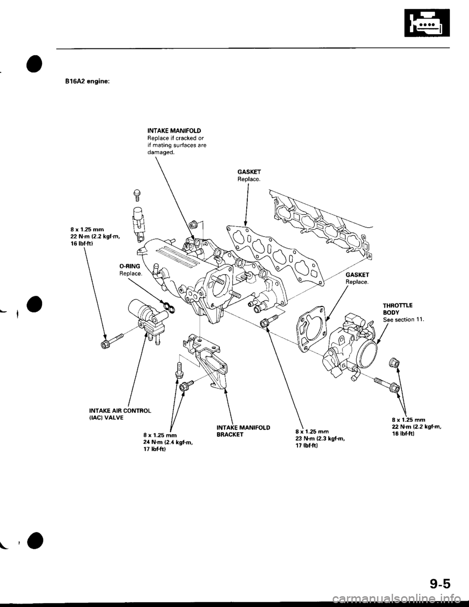
816A2 engine:
INTAKE MANIFOLDReplace if cracked orif mating surfaces areoamageo,
8 x 1.25 mm22 N.rA 12.2 kgl.trr,16 tbtftt
o
t_-lUH
E
INTAKE AIR CONTROLIIACI VALVE
8 x 1.25 mm24 N.m 12.4 kgf.m,17 tbtftl
8 x 1.25 mm23 N.m {2.3 kg{.m,17 tbt.ftl
Al N-m 12.2 kgt.m,16 tbt.ftlMANIFOLDBRACKET
n ""\--
VlCd>-^
M\G
yo
9-5
Page 291 of 2189
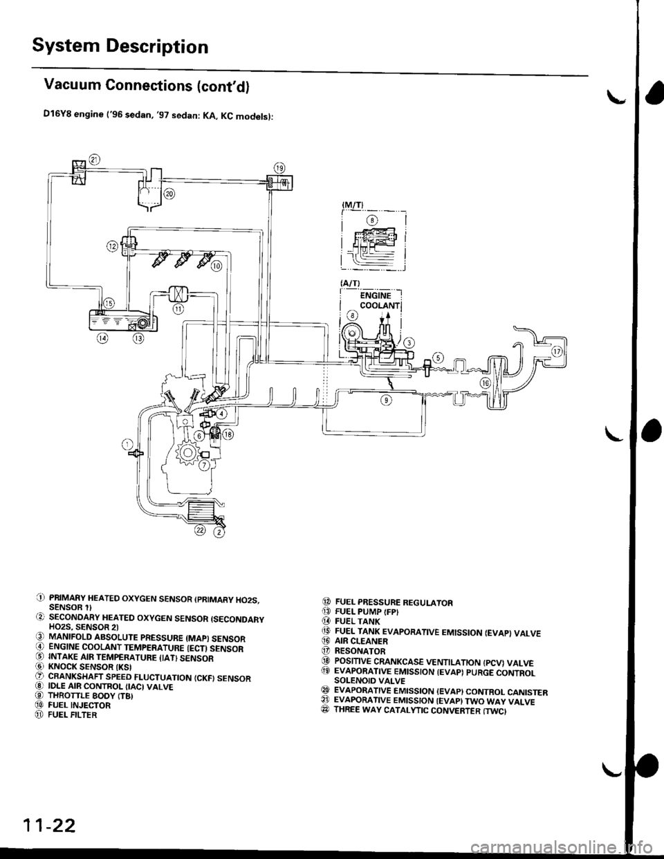
System Description
Vacuum Connections (cont'd)
D16Y8 engine ('96 sedan, '97 sedan: KA, KC modelsl:
PRIMARY HEATED OXYGEN SENSOR (PRIMARY HO2S.SENSOR SECONOARY HEATED OXYGEN SENSOR {SECONDARYHO2S, SENSOR 2lMANIFOLD ABSOLUTE PRESSUBE {MAPI SENSORENGINE COOLANT TEMPERATURE {ECTI SENSORINTAKE AIR TEMPERATUFE IIATI SENSORKNOCK SENSOR IKSICRANKSHAFT SPEED FLUCTUATION {CKFI SENSORIDLE AIR CONTROL IIACI VALVETHROTTLE EODY (T8)FUEL INJECTORFUEL FILTER
FUEL PRESSURE REGULATORFUEL PUMP {FPIFUEL TANKFUEL TANK EVAPORATIVE EMISSION IEVAP} VALVEAIR CLEANERRESONATORPOSITIVE CRANKCASE VENTILATION {PCV} VALVEEVAPORATIVE EMISSION IEVAP) PURGE CONTROLSOLENOID VALVEEVAPORATIVE EMISSION IEVAPI CONTROL CANISTEREVAFORATIVE EMISSION IEVAP} TWO WAY VALVETHREE WAY CATALYTIC CONVERTER (TWC'
{M/T}
i@l: F@i
HiiFl
(A/T)
I ENGINE I
I coor-rruri
i@ i+ il/A. nfi |(Or)l /U[ |)l#t,/,6
0)
t;
-l
@
!o,(t
@@@
@@@(9
@@@(D
@A)@
11-22
Page 374 of 2189
3.
5.
6.
1.
Fuel Cut-off Control
. During deceleration with the throttle valve closed, current to the fuel injectors is cut off to improve fuel economy at
speeds over the following rpm:. D16Y5 engine (M/T):850 rpm. D]6Y5 engine (CVT), D'16Y8 engine (USA M/T): 920 rpm
. Dl6Y8 engine (USA A,/I), D16Y7 engine (USA A,/T);910 rpm
. D16Y8 engine (Canada M/T), D16Y7 engine (canada): 990 rpm
' D16Y8 engine (Canada M/T): 1,000 rpm
. 816A2 engine: 970 rpm
. Fuel cut-off action also takes place when engine speed exceeds 6,900 rpm (D16Y5, D16Y7 engine; D'16Y8 engine:
7,000 rpm. 816A2 engine: 8.100 rpm), regardless of the position of the throttle valve, to protect the engine from
over-rewing. With '99 Dl6Y7 engine (A,/T) and '99 D16Y8 engine (A./T), the PCM cuts the fuel at engine speeds over
5,000 rpm when the vehicle is not moving.
IVC Compressor Clutch Relay
When the ECM/PCM receives a demand for cooling from the air conditioning system, it delays the compressor from
being energized, and enriches the mixture to assure smooth transition to the A,/C mode
Evaporative Emission (EVAP) Purge Control Solenoid Valve*'
When the engine coolant temperature is above 154'F (68'C). the ECM/PCM controls the EVAP purge control solenoid
valve which controls vacuum to the EVAP purge control canister.
Evaporative Emission (EVAP) Purge Control Solenoid Valve*a
When the engine coolant temperature above 154"F (68"C), intake air temperature above 32"F (0'C) and vehicle speed
above 0 mile (0 km/h) or [Ay'C compressor clutch on and intake air temperature above 160"F (41'C)], the ECM/PCM
controls the EVAP purge control solenoid valve which controls vacuum to the EVAP purge control canister.
Exhaust Gas Recirculation (EGR) Control Solenoid Valve*?
When EGR is required for control of oxides of nitrogen (NOx) emissions. the ECM controls the EGR control solenoid
valve which supplies regulated vacuum to the EGR valve
Alternator Control
The system controls the voltage generated at the alternator in accordance with the electrical load and driving mode,
which reduces the engine load to improve the fuel economy.
ECM/PCM Fail-safe/Back-up Functions
1. Fail safe Function
When an abnormality occurs in a signal from a sensor, the ECM/PCM ignores that signal and assumes a pre-pro-
grammed value for that sensor that allows the engine to continue to run.
2. Back-uD Function
When an abnormality occurs in the ECM/PCM itself, the fuel injectors are controlled by a back-up circuit independent
of the system in order to permit minimal driving.
3. Self diagnosis Function lMalfunction Indicator Lamp (MlL)l
When an abnormality occurs in a signal from a sensor, the ECM/PCM supplies ground for the lvllL and stores the DTC
in erasable memory. When the ignition is initially turned on, the ECM/PCM supplies ground for the MIL for two sec-
onds to check the MIL bulb condition.
4. Two Trip Detection Method
To prevent false indications, the Two Trip Detection Method is used for the HO2S, fuel metering-related. idle control
system, ECT sensor, EGR system and EVAP control system self-diagnostic functions. When an abnormality occurs,
the ECM/PCM stores it in its memory. When the same abnormality recurs after the ignition switch is turned OFF and
ON 0l) again, the ECM/PCM informs the driver by lighting the MlL. However, to ease troubleshooting, this function is
cancelled when you jump the service check connector. The MIL will then blink immediately when an abnormality
occurs,
5. Two (or Three) Driving Cycle Detection Method
A "Driving Cycle" consists ot starting the engine. beginning closed loop operation, and stopping the engine. lf misfir-
ing that increases emissions is detected during two consecutive driving cycles, or TWC deterioration is detected dur-
ing three consecutive driving cycles, the ECM/PCM turns the MIL on. However, to ease troubleshooting, this function
is cancelled when you jump the service check connector. The MIL will then blink immediately when an abnormality
occurs.
(cont'd)
1 1-1 05
.1.
Page 444 of 2189
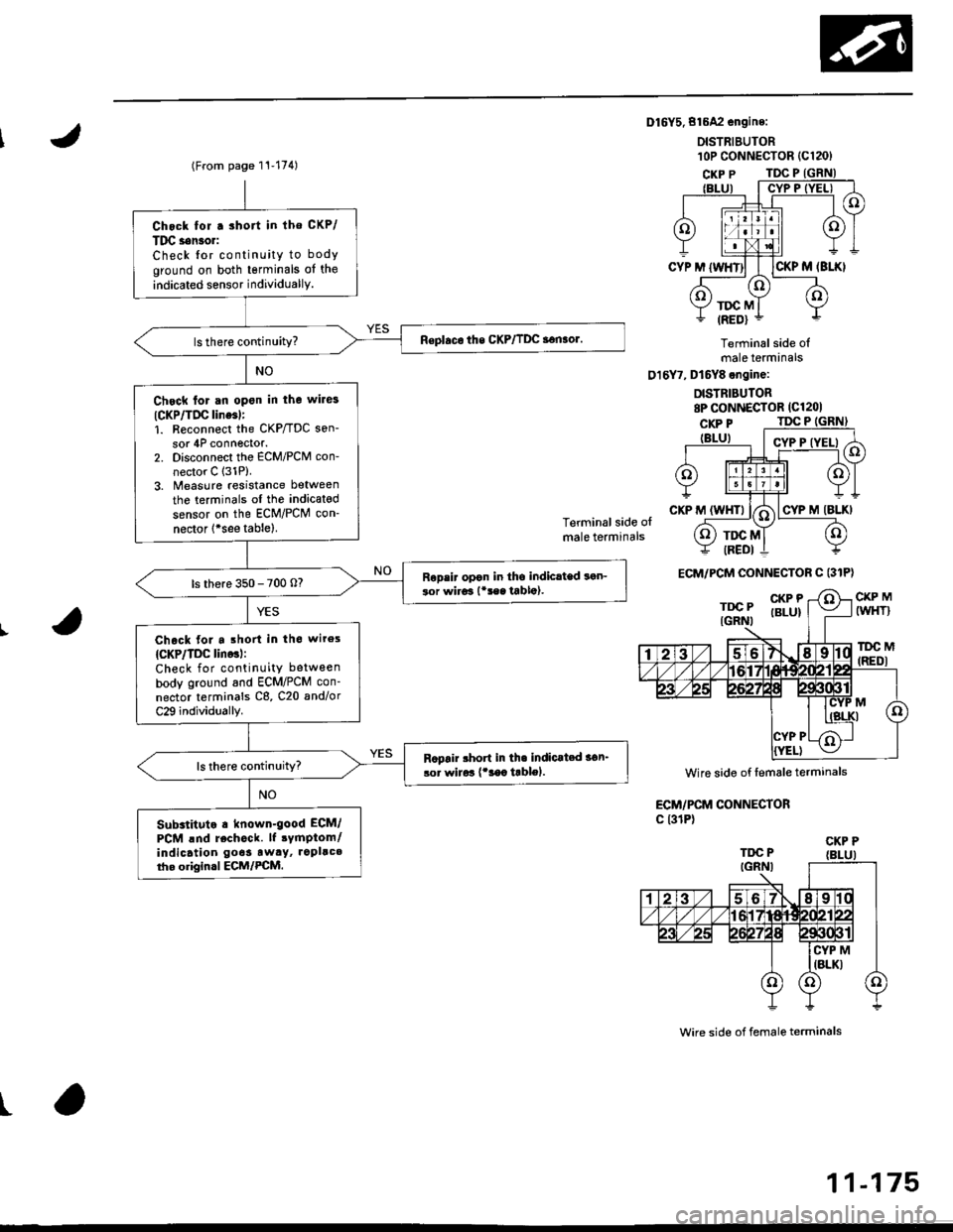
Dl6Y5.816A2 engine:
DISTRIEUTOR
Terminal side olmale terminals
016Y7, Dt6Y8 engine:
DISTRIBUTOR8P CONNECTOR (Cl201
Terminal side olmale terminals
CKP MIWHT}
lDC M(REDI
ECM/PCM CONNECTORc l31P)
wire side of female terminals
t
l0P coNNECTOR {C120)(From page 11-174)
Chock for.3hort in lho CKP/
Tlrc s6n3o.:
Check {or continuity to body
ground on both tsrminals of the
indicated sensor individuallY.
Chsck for an open in the wile3
ICKP/TIrc line6l:1. R€connect the CKP/TDC son-
sor 4P connector.2. Disconnect the ECM/PCM con-
nector C 131P).3. Measure resistance between
the terminals ol the indicated
sensor on the ECM/PCM con-
nector 1*see tablel.
Ropsir opon in tho indiclted son-ior wiro3 l*!sa tabla).ls there 350 - 700 o?
Chack for a .ho in th6 wiros
{CKP/TDC lino3l:Check for continuity between
body ground and ECM/PCM con-
nector terminals C8, C20 and/or
C29 individually.
Rcpair rhort in th. indicat.d 36n_
lor wirar {'3ac trblol.
Substituto . known-good ECM/
PCM lnd rechock. lf 3ymptom/indicatlon go6s aw.y, ropllc.tho origin.l ECM/PCM.
ECM/PCM CONNECTOR C (31P)
Wire side of femsle terminals
CKP P
11-175
Page 506 of 2189
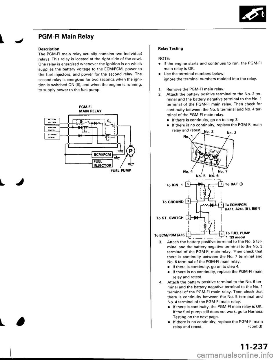
I
PGM-FlMain Relay
Description
The PGM-Fl main relav actuallv contains two individual
relays. This relay is located at the right side of the cowl.
One relay is energized whenever the ignition is on which
supplies the battery voltage to the ECM/PCM, power to
the luel iniectors, and power for the second relay. The
second relay is energized lor two seconds when the igni-
tion is switched ON (lll, and when the engine is running,
to supply power to the luel pump.
PGM-FIMAIN RELAY
J
I
t
FUEL PUMP
Relay Testing
NOTE:
. It the engine starts and continues lo run. the PGM Fl
main relay is OK.
. Use the terminal numbers below;
ignore the terminal numbers molded into the relay,
1. Remove the PGM Fl main relay.
2. Attach the battery positive terminal to the No. 2 ter-
minal and the battery negative terminal to the No 1
terminal of the PGM-Fl main relay. Then check for
continuity between the No.5 terminal and No 4ter-
minal of the PGM Fl main relay.
. lf there is continuity, go on to step 3.
. lf there is nocontinuity, replacethe PGM-Fl main
relay and retest.No. 3No. 1
To lGN. 1
To GROUND
To ST. SWITCH
To ECM/PCM {A161
To 8AT O
To ECM/PCM{(a11, A241, (81. B9l*l
To FUEL PUMP.r '99 model
3.Altach the batterv positive terminal to the No.5 ter-
minal and the battery negative terminal to the No. 3
terminal of the PGM-Fl main relay. Then check that
there is continuity between the No. 7 terminal and
No. 6 terminal of the PGM-Fl main relay.
. lf there is continuity, go on to step 4
. lf there is nocontinuity, replacethePGM-Fl main
relay and retest.
Attach the battery positive terminal to the No. 6 ter-
minal and the battery negative terminal to the No. 1
terminal of the PGM Fl main relay. Then check that
there is continuity between the No. 5 terminal and
No. 4 terminal of the PGM-Fi main relay.
. lf there is continuity, the PGM-Fl main relay is OK.
lf the fuel pump still does not work, go to Harness
Testing on the next page.
. lf there is no continuity, replace the PGM Fl main
4.
(cont'd)
11-237
relay and retest.