alternator HONDA CIVIC 2002 7.G User Guide
[x] Cancel search | Manufacturer: HONDA, Model Year: 2002, Model line: CIVIC, Model: HONDA CIVIC 2002 7.GPages: 1139, PDF Size: 28.19 MB
Page 67 of 1139
Charging System
Alternator Overhaul (cont'dl
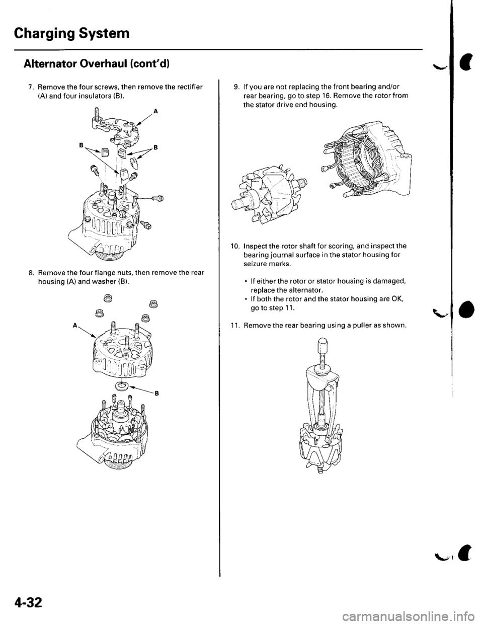
7. Remove the four screws, then remove the rectifier
(A) and four insulators (B).
Remove the four flange nuts, then remove the rear
housing (A) and washer (B).
o\
4-32
f.r,e
9. lf you are not replacing the front bearing and/or
rear bearing, go to step '16. Remove the rotor from
the stator drive end housing.
Inspect the rotor shaft for scoring, and inspect the
bearing journal surface in the stator housing for
setzure marks.
. lf eitherthe rotororstatorhousing isdamaged,
replace the alternator,. lf both the rotor and the stator housing are OK,
go to step 11.
'l 1. Remove the rear bearing using a puller as shown.
10.
\"
Page 69 of 1139
Charging System
Alternator Overhaul (cont'd)
Rectitier Test
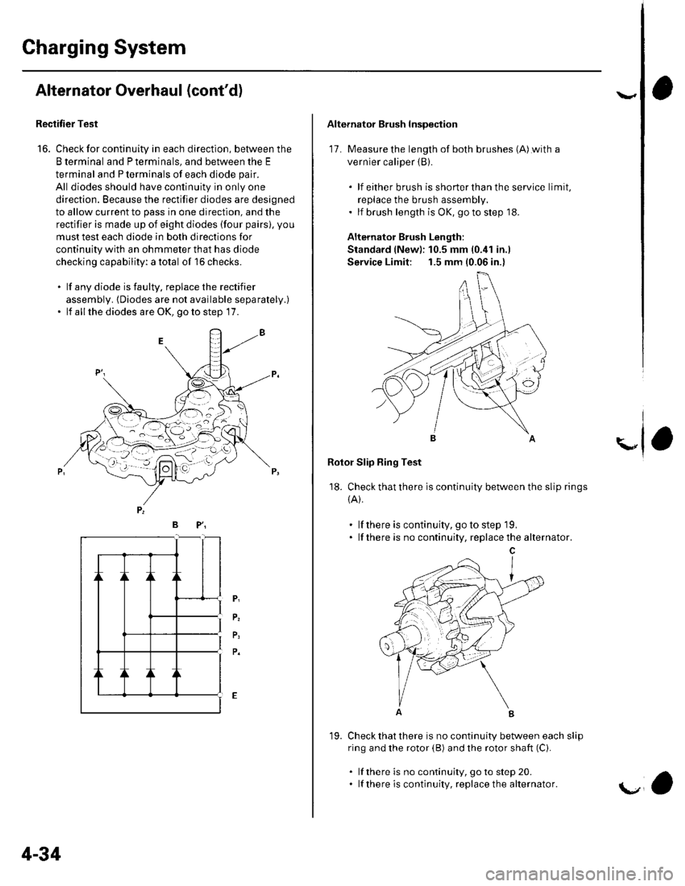
16. Check for continuity in each direction, between the
B terminal and P terminals, and between the E
terminal and P terminals of each diode pair.
All diodes should have continuity in only one
direction. Because the rectifier diodes are designed
to allow current to pass in one direction, and the
rectifier is made up of eight diodes (four pairs). you
musttest each diode in both directions for
continuity with an ohmmeter that has diode
checking capability: a total of 16 checks.
. lf any diode is faulty. replace the rectifier
assembly. {Diodes are not available separately.)' lf all the diodes are OK, go to step 17.
/--:',t- -L . --- -o \-- l'-=
BP"
P,
P.
P,
P.
4-34
19.
'a
Alternator Brush Inspection
17. Measure the length of both brushes (A)with a
vernier caliper {B).
. lf either brush isshorterthanthe service limit,
replace the brush assembly.. lf brush length is OK, go to step '18.
Alternator Brush Length:
Standard (New): 10.5 mm (0.41 in.)
Service Limit: 1.5 mm (0.06 in.)
Rotor Slip Bing Test
18. Check that there is continuity between the slip rings
{A).
. lf there is continuity, go to step 19.. lf there is no continuity, replacethe alternator.
Check that there is no continuity between each slip
ring and the rotor (B) and the rotor shaft (C).
. lf there is no continuity, goto step 20.. lf there is continuity, replace the alternator.
\"
Page 70 of 1139
Stator Test
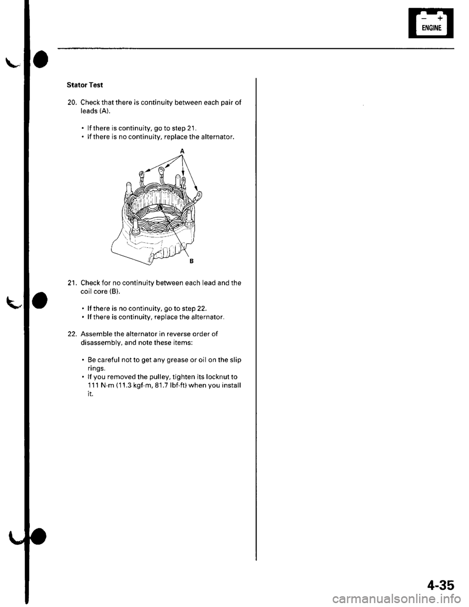
20. Checkthatthere is continuity between each pair of
leads (A).
lf there is continuity, go to step 21 .
lf there is no continuity, replace the alternator.
Check for no continuity between each lead and the
coil core (B).
. lf there is no continuity, goto step 22.. lfthere is continuity, replace the alternator.
Assemble the alternator in reverse order of
disassembly, and note these items:
. Be careful not to get any grease or oil on lhe slip
n ngs.. lf you removed lhe pulley, tighten its locknutto
111 N.m (11.3 kgf m,81.7 lbf.ft)whenyou install
it.
21.
22.
'--l-- --i
4-35
Page 208 of 1139
Fuel and Emissions
Fuel and Emissions Systems
SpecialTools
General Troubleshooting
Information
DTC Troubleshooting lndex ....
Symptom Troubleshooting
1ndex...............
System Descriptions ................
Howto Set Readiness Codes ..
PGM-FlSystem
Component Location Index ....
DTC Troubleshooting ..............
MIL Circuit Troubleshooting ...
DLC Circuit Troubleshooting ..
Injector Replacement ...............
A,/F Sensor Replacement .........
Secondary HO2S
Replacement
ECT Sensor Reolacement .......
CMP Sensor B {TDC Sensor)
Replacement
IAT Sensor Replacement .........
Knock Sensor Replacement ....
CKP Sensor Reolacement .......
VTEC/VTC
Comoonent Location Index ....
DTC Troubleshooting ..............
VTC Oil Control Solenoid
Valve Removal/Test .............
CMP Sensor A Replacement ...
VTEC Solenoid Valve
Removal/lnsoection .............
ldle Control System
Component Location Index
DTC Troubleshooting ..............
A,/C Signal Circuit
TroubleshootinS ...................
Alternator FR Signal Circu it
TroubleshootinS ...................
EPS Signal Circuit
TroubleshootinS ...................
Brake Pedal Position Switch Signal
Circuit Troubleshooting .............
ldle Speed Inspection
ECM ldle learn Procedure .......
Fuel Supply System
Component Location Index
Fuel Pump Circuit Troubleshooting
1't-2
I I-J
11-7
1 1-10
11-12
11-46
11-49
11-52
11-97
11-109
11-111
11-113
11-113
11-114
11-114
11-115
11-115
11-116
11-117
1 1-1 18
11-127
11-128
11-128
11-129
1I-130
I t- t55
11-134
1 1- 135
1 1-137
1 1-138
1 1-139
1 1-140
11-141
11-144
Fuel PressureTest ................... 11-145
Fuel Lines Inspection ............... 11-146
Fuel Line/Ouick-Connect
Fittings Precautions ............. 1 1-148
Fuel Line/Ou ick-Con nect
Fittings Removal .................. 1 1-149
Fuel Line/Ou ick-Con nect
Fittings lnstallation ............... 11-150
Fuel Pressure Regu lator
Replacement ......................... 11-152
Fuel Fifter Replacement ........... 11-152
Fuel Pump/Fuel Gauge Sending
UnitReDlacement ................. 11-153
Fuel Pulsation Damoer
Rep1acement ......................... 11-154
Fuel Tank Reolacement ........... 11-155
Fuel GaugeSending UnitTest ....... 11-156
Low Fuel lndicatorTest ................. 1 1-158
Intake Air System
Comoonent Location Index .... 11-159
Throttle BodyTest ................... 11-160
Intake Air Bypass Control
Thermal Valve Test .............. 11-161
Air Cleaner Reolacement ........ 11-162
Air Cleaner Element
Reolacement ......................... 11-162
Throttle Cable Adjustment ...... 11-163
Th rottle Cable
Removal/lnstallation ............ 1 1-164
Th rottle Body Removal/
Installation .. 11-165
Th rottle Body Disassembly/
Reassemblv .......................... 11-166
Catalytic Converter System
DTC Troubleshooting .............. 1 1-167
PCV System
DTC Troubleshooting .............. 1 1-168
PCV Valve InsDection
and Test ...... 1 1- 169
PCV Valve Reolacement .......... 11-169
EVAP System
Component Location Index .... 11-170
DTCTroubleshooting .............. 11-171
EVAP Two Way Valve Test ...... 11-186
Fuel Tank Vaoor Control
Valve Test ... 11-187
EVAP Canister Replacement ... 11-189
Fuel Tank Vaoor Control
Valve Reolacement .............. 1 1-189Fuel Pressu re Relieving ...........
Page 217 of 1139
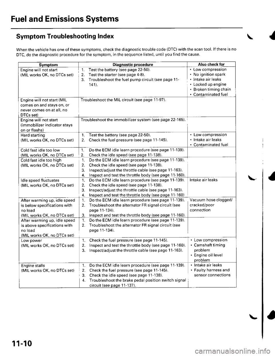
Fuel and Emissions Systems
Symptom Troubleshooting Index
When the vehicle has one of these symptoms, check the diagnostic trouble code (DTC) with the scan tool. lf there is no
DTC, do the diagnostic procedure for the symptom, in the sequence listed, until you find the cause.
SvmotomDiaqnostic procedureAlso check lor
Engine will not sta rt
(MlL works OK, no DTCS set)
1. Test the battery {see page 22-50).
2. Test the starter (see page 4-8).
3. Troubleshoot the fuel pump circult (see page 11
141).
Low compressron
No ignition spark
lntake air leaks
Locked up engine
Broken timing chain
Contaminated fuel
Engine will not start (MlL
comes on and stays on, or
never comes on at all, no
DTCS set)
Troubleshoot the l\4lL circuit (see page 1 '1-97).
Engine will not start
(immobilizer indicator stays
on or flashs)
Troubleshoot the immobilizer system (see page 22-165).
Hard starting(MlL works OK, no DTCS set)
1. Testthe battery (see page 22-50).
2. Checkthe fuel pressure (see page 11-145).
Low compression
Intake air leaks
Contaminated fuel
Cold fast idle too low(MlL works OK. no DTCS set)
1. Do the ECM idle learn procedure (see page 11-139).
2. Checkthe idle sDeed (see paqe 11-138).
Cold fast idle too high
(MlL works OK, no DTCS set)
Do the ECI\4 idle learn procedure (see page 1 1- 139).
Checkthe idle speed {see page 11-138).
Inspect/adjust the throttle cable (see page 1 '1-'163).
Inspect and test the throttle body {see page 1 1-160}.
']�
2.
3.
ldle speed fluctuates
(MlL works OK, no DTCS set)
1. Dothe ECM idle learn procedure (see page 11-'139).
2. Check the idle speed (see page 11-138).
3, Inspecvadjust th e throttle cable (see page 11''163).
4. Insoect and test the throttle bodv (see paqe 11- 160)
Intake air leaks
After warming up, idle speed
is below specifications with
no load
{MlL works OK, no DTCS set)
1. Do the ECIVI idle learn procedure (see page 1 1- 139).
2. Troubleshootthe alternator FR signal circuit (see
page 11-'134).
3. InsDect and test the throttle bodv {see paqe 1 1-160).
Vacuum hose clogged/
cracked/poor
connectron
After warming up, idle speed
is above specifications with
no toao(MlL works OK. no DTCS set)
1. Do the ECM idle learn procedure {see page 1'j-139).
2. Troubleshoot the alternator FR signal circuit(see
page 11-134).
Low power
(MlL works OK, no DTCS set)
1. Check the fuel pressure(seepagell-145).
2. Inspect and test the th roftle body (see page 11-160).
3. Inspecvadjust the throttle cable (see page 11-'163).
Low compressron
Camshaft timing
problem
Engine oil levelprootem
Engine stalls(MlL works OK. no DTCS set)
1. Do the ECM idle learn procedure (see page 1'l'139).
2. Check the fuel pressure{seepagell-145).
3. Check the idle speed (see page I 1-138).
4. Troubleshootthe brake pedal position switch signal
circuit (see paqe 11-137).
lntake air leaks
Faulty harness and
sensor connections
\
\-
11-10
\-
Page 228 of 1139
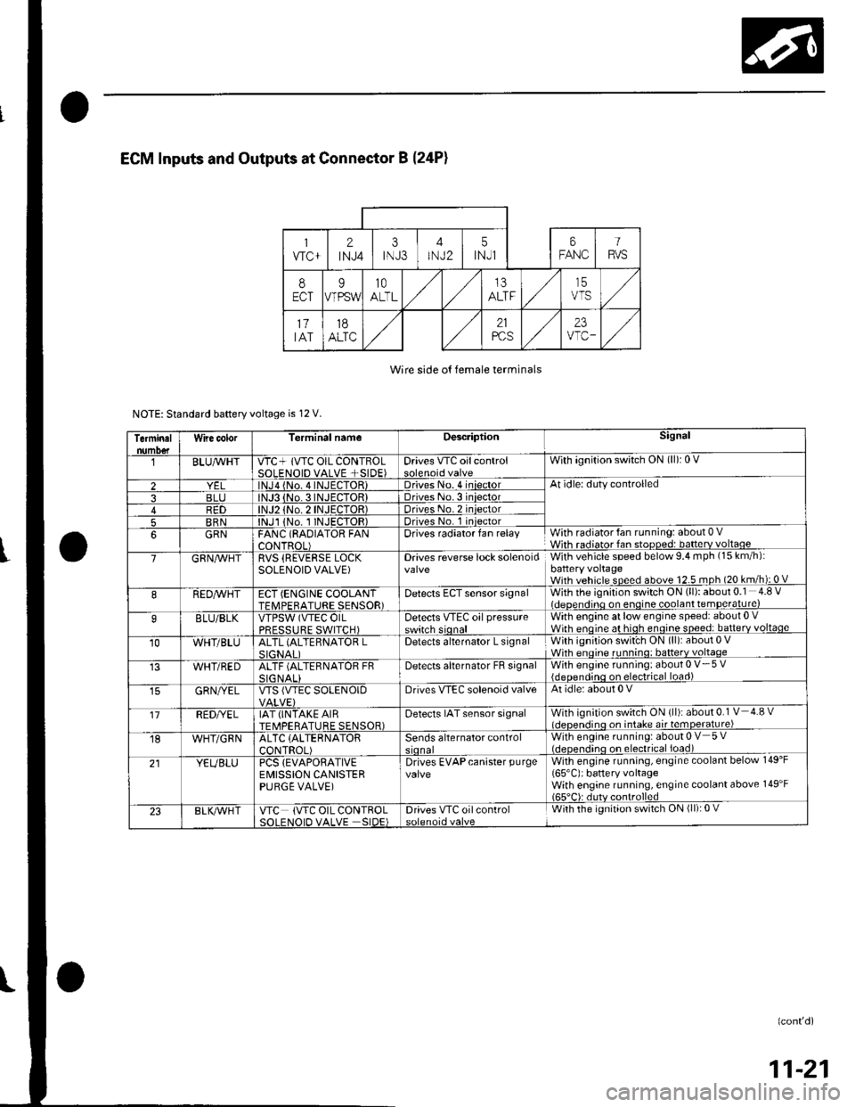
Wire side o{ female terminals
NOTE: Standard baftery voltage is 12 V.
Terminalnumo€tWire color[erminal nameDescriptionSignal
BLUAvHTVTC+ lVTC OIL CONTBOLSOLENOID VALVE +SIDE)Drives VTC oilcontrolWith ignition switch ON (ll): 0 V
2lNJa {No. 4INJECTOR)Driveso. 4 iniectorAt idle: duty controlled
3BLJo.3INJECTORIDriveso.3 iniector4R1)TOR)Driveso.2 iniector
5BRNlNJl 1No. I INJECTOR)Drives No. 1 iniector
6GRNFANC (RAOIATOR FANCONTROL)Drives radiator fan relayWith radiator fan running: about 0 VWith radiator fan stopped: batterv voltaoe
7GRN/vVHTRVS (REVERSE LOCKSOLENOID VALVE)Drives reverse lock solenoidWith vehicle speed below 9.4 mph (15 km/h):battery voltageWith vehicle speed above 12.5 mph (20 km/h): 0 V
8REDAVHTECT (ENGINE COOLANTTFMPFRATURE SENSOR)Detects ECT sensor signalWith the ignition switch ON (ll): about 0.1 4.8 Videoendino on enoine coolant temDerature)
9BLU/BLKVTPSW (VTEC OILPRFSSTIRF SWITCH)Detects VTEc oil pressureswitch sionalWith engine at low engine speed: about 0 .Wirh enoine at hioh enoine soeed: batterv voltaqe
10WHT/BLUALTL (ALTEBNATOR LSIGNAI IDetects alternator L signalWith ignition swit'ch ON (ll): about 0 VWhh enoine runnino: batterv voltaqe
WHT/REDALTF (ALTERNATOR FRSIG NALIDetecls alternator FB signalWith engine running: about 0 V- 5 V{deoendinq on electrical load)
GRN/YELVTS {VTEC SOLENOIDDrives VIEC solenoid valveAt idle: about 0 V
'17REDI/ELIAT (INTAKE AIRTEMPERATURE SENSOR)Detects IAT sensor signalWith ignition switch ON {ll): about 0.1 V 4.8 vl.lcnen.iino on intake air temoerature)
18WHT/GRNALTC (ALTERNATOR
CONTROL)Sends alternator controlWith engine running: about 0 V 5 V(.lcocn.lino on electrical ioad)
21YEUBLUPCS {EVAPORATIVEEMISSION CANISTERPURGE VALVE)
Drives EVAPcanister purgevalveWith engine running, engine coolant below 149'F
165'C): battery voltageWith engine running, engine coolant above 149'F165"C): dutv controlled
23BLK/Vr'HTVTC (VTC OIL CONTROLSOI FNOID VALVE SIDE)Drives VTC oilcontrolWith the ignition switch ON (ll): 0 V
(confd)
11-21
Page 239 of 1139
Fuel and Emissions Systems
(
{
System Descriptions (cont'd)
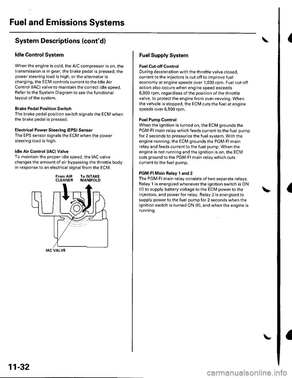
ldle Control System
When the engine is cold, the Ay'C compressor is on, the
transmission is in gear, the brake pedal is pressed. thepower steering load is high, or the alternator is
charging, the ECIM controls current to the ldle Air
Control (lAC) valve to maintain the correct idle speed.
Refer to the System Diagram to see the functional
layout of the system.
Brake Pedal Position Switch
The brake pedal position switch signals the ECM when
the brake pedal is oressed.
Electrical Power Steering (EPS) Senser
The EPS sensor signals the ECM when the power
steering load is high.
ldle Air Control llACl Valve
To maintain the proper idle speed, the IAC valve
changes the amount of air bypassing the throttle body
in response to an electrical signal from the ECM.
From AIR To INTAKECLEANER MANIFOLD
IAC VALVE
11-32
Fuel Supply System
Fuel Cut-off Control
During deceleration with the throttle valve closed,
current to the injectors is cut off to improve fuel
economy at engine speeds over 1,030 rpm. Fuel cut-off
action also occurs when engine speed exceeds
6,900 rpm, regardless of the position of the throttle
valve, to protect the engine from over-rewing. When
the vehicle is stopped. the ECM cuts the fuel at engine
speeds over 6,500 rpm.
Fuel Pump Control
When the ignition is turned on, the ECM grounds the
PGM-Fl main relay which feeds current to the fuel pump
for 2 seconds to pressurize the fuel system, With the
engine running. the ECM grounds the PGM-Fl main
relay and feeds current to the fuel pump. When the
engine is not running and the ignition is on, the ECI\4
cuts ground to the PGM-Fl main relay which cuts
current to the fuel pump.
PGM-FI Main Relay 1 and 2
The PGM-Fl main relay consists of two separate relays.
Relay 1 is energized whenever the ignition switch is ON(ll) to supply battery voltage to the ECM power to the
injectors, and power for relay, Relay 2 is energized to
supply power to the fuel pump for 2 seconds when the
ignition switch is turned ON (ll), and when the engine is
runnrng.
Page 341 of 1139
ldle Gontrol System
't.
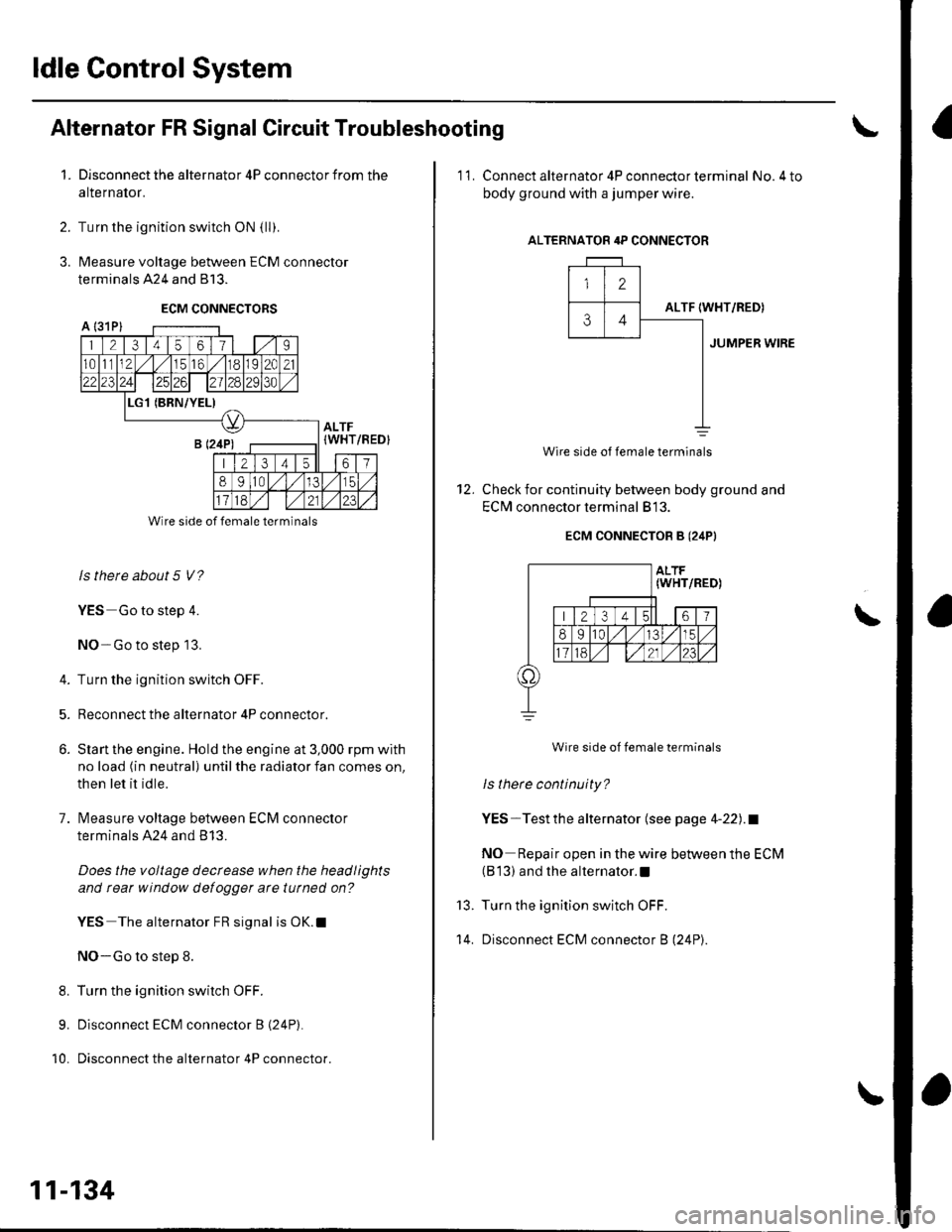
Alternator FR Signal Circuit Troubleshooting
Disconnect the alternator 4P connector from the
alternalor.
Turn the ignition switch ON {ll).
Measure voltage between ECM connector
terminals 424 and 813.
ECM CONNECTORS
2.
3.
A l31Pl
1 21345611 | 1.,'I
1011112,/56,/r8119l2C21
2312428129130
L(BRN/YEL)
ALTF(WHT
213 4t561
89ltal,/l/15
Wire side of female terminals
ls there about 5 V?
YES Go to step 4.
NO-Go to step 13.
4. Turn the ignition switch OFF.
5. Reconnect the alternator 4P connector.
6. Slan the engine. Hold the engine at 3,000 rpm with
no load (in neutral) until the radiator fan comes on,
then let it idle.
7. lvleasure voltage between ECM connector
terminals A24 and B 13.
Does the voltage decrease when the headlights
and rear window defogger arc tutned on?
YES The alternator FR signal is OK.l
NO-Go to step 8.
8. Turn the ignition switch OFF.
9. Disconnect ECM connector B (24P).
10. Disconnect the alternator 4P connector.
/REDI
11-134
'11. Connect alternator 4P con necto r term inal No.4 to
body ground with a jumper wire.
ALTERNATOR 4P CONNECTOR
12
ALTF34IWHT/RED)
JUMPER WIRE
12.
Wire side of female terminals
Check for continuity between body ground and
EClvl connector terminal 813.
ECM CONNECTOB B (24PI
Wire side of female terminals
ls there continuity?
YES-Testthe alternator (see page 4-22).1
NO Repair open in the wire between the ECM(B 13) and the alternator.l
Turn the ignition switch OFF.
Disconnect ECM connector B (24P).
\
13.
't 4.
Page 342 of 1139
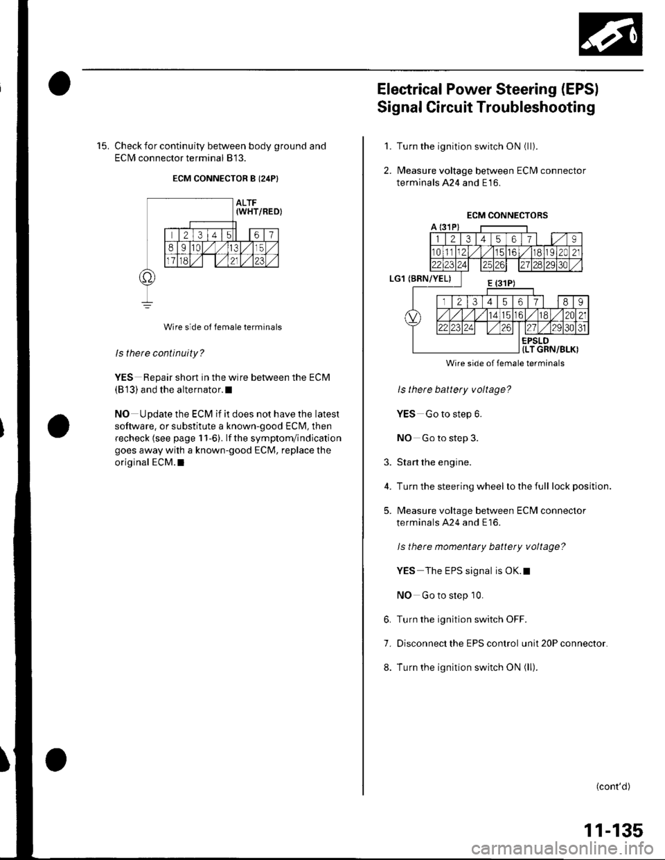
15. Check for continuity between body ground and
ECIM connector terminal 813.
ECM CONNECTOR B I24P}
Wire side of female terminals
ls there continuity?
YES Repair short in the wire between the ECM
(813) and the alternator.l
NO Update the ECM if it does not have the latest
software, or substitute a known-good ECM, then
recheck lsee page 1 1-6). lf the symptom/indication
goes away with a known-good ECM, replace the
original ECM.I
Electrical Power Steering (EPSI
Signal Circuit Troubleshooting
Turn the ignition switch ON (ll).
l\4easure voltage between ECM connector
terminals 424 and E16.
1.
2.
3.
4.
5.
Wire side of female terminals
ls there battery voltage?
YES Go to step 6.
NO Go to step 3.
Start the engine.
Turn the steering wheel lo the full lock position.
l\4easure voltage between ECM connector
terminals A24 and E16.
ls there momentaty battery voltage?
YES The EPS signal is OK.t
NO Go to step 10.
6. Turn the ignition switch OFF.
7. Disconnect the EPS control unit 20P connector.
8. Turn the ignition switch ON (ll).
(cont'd)
11-135
Page 818 of 1139
Compressor Replacement
1. lf the compressor is marginally operable, run the
engine at idle speed, and let the air conditioning
work for a few minutes, then shut the engine off.
2. Make sure you have the anti-theft code for the radio,
then write down the frequencies for the radio's
preset buttons.
3. Disconnect the negative cable from the battery.
4. Recover the refrigerant with a recovery/recycling/
charging station (see page 21-53).
5. Remove the alternator (see page 4-29).
6. Remove the Ay'C condenser fan assembly (see page
10-10).
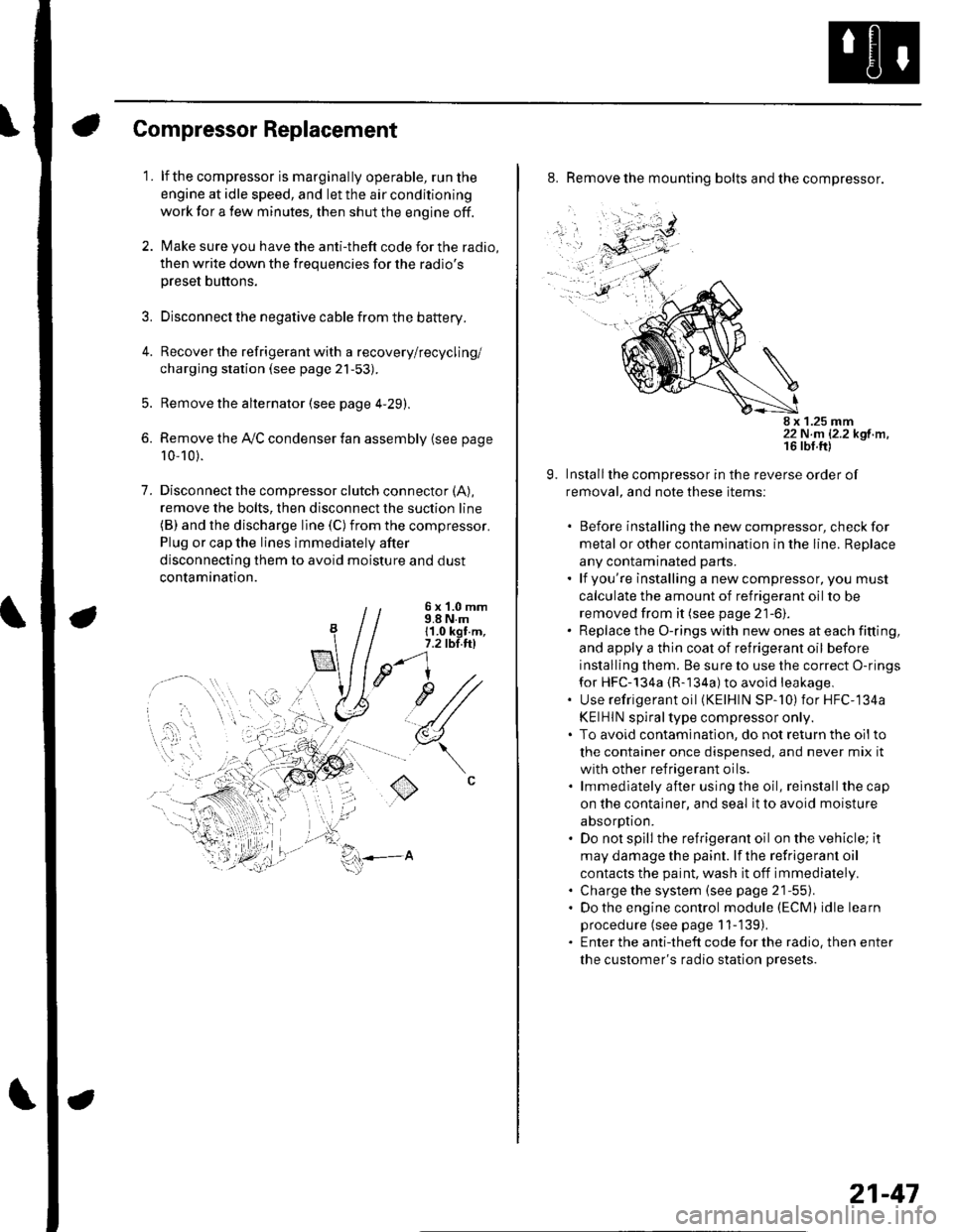
7. Disconnectthe compressor clutch connector (A),
remove the bolts, then disconnect the suction line(B) and the discharge line (C)from the compressor.
Plug or cap the lines immediately after
disconnecting them to avoid moisture and dust
contamination.
6 x '1.0 mm9.8 N.m11.0 kgt.m,7.2 tbl.ttl
u1/
(
o
8. Remove the mounting bolts and the compressor.
8 x 1.25 mm22 N.m 12.2 kgf.m.
9. Installthe compressor in the reverse order of
removal, and note these items:
. Before installing the new compressor, check for
metal or other contamination in the line. Replace
any contaminated parts.. lf you're installing a newcompressor, you must
calculate the amount of refrigerant oil to be
removed from it (see page 21-6).. Replace the O-rings with new ones at each fitting,
and apply a thin coat of refrigerant oil before
installing them. Be sure to use the correct O-rings
for HFC-134a {R-134a) to avoid leakage,. Use refrigerant oil (KElHlN SP-'10) for HFC-134a
KEIHIN spiral type compressor only.. To avoid contaminatlon, do not return the oilto
the container once dispensed, and never mix it
with other refrigerant oils.. lmmediately after using the oil, reinstallthe cap
on the container, and seal it to avoid moisture
absorption.. Do not spill the refrigerant oil on the vehicle; it
may damage the paint. lf the refrlgerant oil
contacts the paint, wash it off immediately.. Charge the system (see page 21-55).. Do the engine control module (ECM) idle learn
procedure (see page 11-'139).. Enter the antitheft code for the radio, then enter
the customer's radio station presets.
21-47