battery replacement HONDA CIVIC 2002 7.G User Guide
[x] Cancel search | Manufacturer: HONDA, Model Year: 2002, Model line: CIVIC, Model: HONDA CIVIC 2002 7.GPages: 1139, PDF Size: 28.19 MB
Page 810 of 1139
Dust and Pollen Filter Replacement
The dust and pollen filters should be replaced every
30,000 miles (48.000 km) or 24 months whichever
comes first. Replace the filters more often if the air flow
is less than usual.
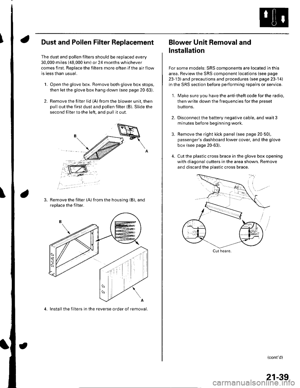
1. Open the glove box. Remove both glove box stops,
then let the glove box hang down (see page 20 63).
2. Remove the filter lid (A)from the blower unit, then
pull out the first dust and pollen filter (B). Slide the
second filter to the left, and pull it out.
Remove the filter {A) from the housing (B), and
replace the filter.
4. Install the filters in the reverse order of removal.
Blower Unit Removal and
lnstallation
For some models: SRS components are located in this
area. Review the SRS component locations (see page
23-13) and precautions and procedures (see page 23-14)
in the SRS section before performing repairs or service.
1. Make sure you have the anti-theft code for the radio,
then write down the frequencies for the preset
buttons.
2. Disconnect the battery negative cable, and wait 3
minutes before beginning worK.
3. Remove the right kick panel (see page 20-50),
passenger's dashboard lower cover, and the glove
box {see page 20-63).
4. Cut the plastic cross brace in the glove box opening
with diagonal cutters in the area shown. Remove
and discard the plastic cross brace,
Cut heare.
{cont'd)
21-39
Page 814 of 1139
Heater Unit/Core Replacement
SRS components are located in this area. Review the
SRS component locations (see page 23'13), and
precautions and procedures (see page 23-14) in the SRS
section before performing repairs or service.
1. Make sure you have the anti-theft code forthe radio,
then write down the freouencies for the radio's
Dreset buttons.
4.
Disconnect the negative cable from the battery,
Disconnect the suction and receiver lines from the
evaporator core (see page 21-42).
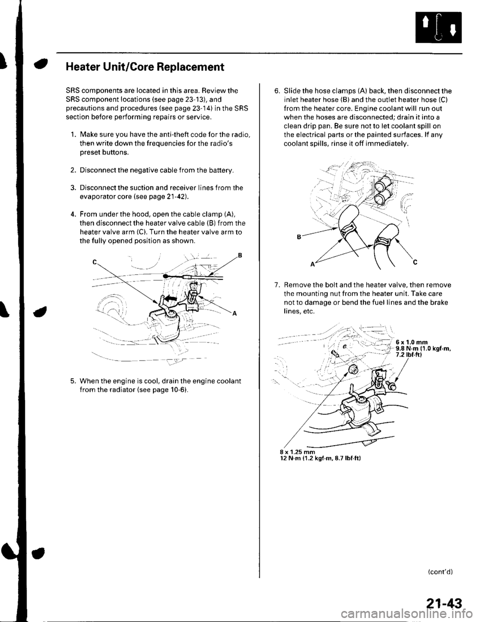
From under the hood, open the cable clamp (A),
then disconnect the heater valve cable (B) from the
heater valve arm (C). Turn the heater valve arm to
the fully opened position as shown
When the engine is cool, drain the engine coolant
from the radiator (see page 10-6).
6. Slide the hose clamps (A) back, the n d isconnect the
inlet heater hose (B) and the outlet heater hose (C)
from the heater core. Engine coolant will run out
when the hoses are disconnected; drain it into a
clean drip pan. Be sure not to let coolant spill on
the electrical parts or the painted surfaces. lf any
coolant spills, rinse it off immediately.
Remove the bolt and the heater valve, then remove
the mounting nut from the heater unit. Take care
not to damage or bend the fuel lines and the brake
lines, etc.
7.
8 x 1.25 mm12 N.m (1.2 kgf.m,8.7lbf.ft)
(cont'd)
21-43
Page 818 of 1139
Compressor Replacement
1. lf the compressor is marginally operable, run the
engine at idle speed, and let the air conditioning
work for a few minutes, then shut the engine off.
2. Make sure you have the anti-theft code for the radio,
then write down the frequencies for the radio's
preset buttons.
3. Disconnect the negative cable from the battery.
4. Recover the refrigerant with a recovery/recycling/
charging station (see page 21-53).
5. Remove the alternator (see page 4-29).
6. Remove the Ay'C condenser fan assembly (see page
10-10).
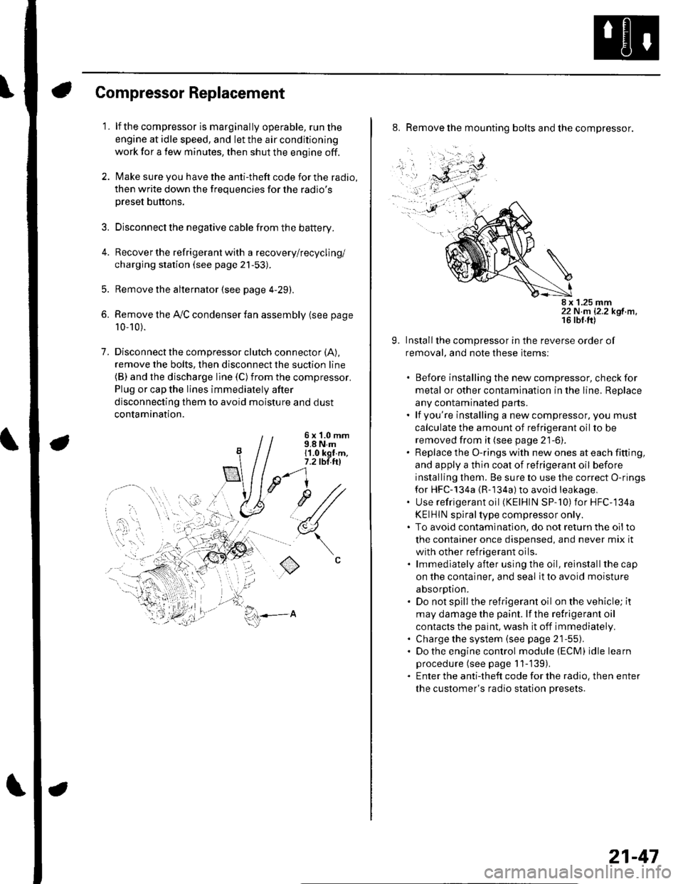
7. Disconnectthe compressor clutch connector (A),
remove the bolts, then disconnect the suction line(B) and the discharge line (C)from the compressor.
Plug or cap the lines immediately after
disconnecting them to avoid moisture and dust
contamination.
6 x '1.0 mm9.8 N.m11.0 kgt.m,7.2 tbl.ttl
u1/
(
o
8. Remove the mounting bolts and the compressor.
8 x 1.25 mm22 N.m 12.2 kgf.m.
9. Installthe compressor in the reverse order of
removal, and note these items:
. Before installing the new compressor, check for
metal or other contamination in the line. Replace
any contaminated parts.. lf you're installing a newcompressor, you must
calculate the amount of refrigerant oil to be
removed from it (see page 21-6).. Replace the O-rings with new ones at each fitting,
and apply a thin coat of refrigerant oil before
installing them. Be sure to use the correct O-rings
for HFC-134a {R-134a) to avoid leakage,. Use refrigerant oil (KElHlN SP-'10) for HFC-134a
KEIHIN spiral type compressor only.. To avoid contaminatlon, do not return the oilto
the container once dispensed, and never mix it
with other refrigerant oils.. lmmediately after using the oil, reinstallthe cap
on the container, and seal it to avoid moisture
absorption.. Do not spill the refrigerant oil on the vehicle; it
may damage the paint. lf the refrlgerant oil
contacts the paint, wash it off immediately.. Charge the system (see page 21-55).. Do the engine control module (ECM) idle learn
procedure (see page 11-'139).. Enter the antitheft code for the radio, then enter
the customer's radio station presets.
21-47
Page 831 of 1139
\Body Electrical
Body ElectricalSpecialToolsGeneral Troubleshooting tntorrnaiion.'......
Relay and Control Unit Locations .....
Connectors and Harnesses
Fuse/Relay Boxes ...............................
Power Distribution .............................
Ground Distribution ...........................
Under-dash Fuse/Relay Box ..............
Battery ..............
Relays ................
*lgnition Switch ..............
*Gauges
Component Location Index .......................Self-diagnostic Procedure ..........................Circuit DiagramGauge Bulb Replacement ..........................Gauge Assembly ReplacementCoolant Temperature
Gauge Troubleshooting .... ....................Vehicle Speed Signal CircuitTroubleshootingVSS Replacement
Exterior LightsComponent Location Index .......................Circuit DiagramDaytime Running Lights ControiUnit Input Test (Canada) ........................Headlight Ad,ustment .................. .. .....Headlighr Replacement ..............................Combination Light SwitchTest/ReplacementBulb ReplacementTaillight Replacement ..........................High Mount Brake Light Replacement ......License Plate Light Replacement ..............Side Marker Light Replacement ................Brake Pedal Position Switch Test ..............Side Turn Signal Light Replacement ........
Turn Signal/HazardFlasher SystemComponent Location Index .......................Circuit DiagramTurn Signal/Hazard Relay lnputTest ........Hazard Warning Switch Test
22,3
22-7
22-13
22-44
22-46
22-4A
22-49
22-50
22-51
22-53
22-5422-5622-5422 6322-64
22-64
22-6522 61
22-6822--71
22-7 622-7422-79
22-AO22-4122-8222-4222-4322-4322-4422-84
22-8�522 A622-8722-88
22-10422-105
22-10622-107
Entry Lights control systemComponent Location Index ....................... 22-89Circuit Diagram ......... 22 90lgnition Key Switch Test .....................,...... 22-9'llgnition Key Light Test ............................... 22-91Control Unit Input Test ..........,.................... 22 92
Interior LightsComponent Location Index ....................... 22-94Circuit Diagram ......... 22-95Ceiling LighVSpotlightsTesVReplacement ................................... 22-96Rear Ceiling Light TesVReplacem ent ........ 22-96Cargo Area Light Test/Replacem ent ......... 22-97Hatch Latch Switch Test ..,..,....................... 22-97
*Audio SystemComponent Location Index ....................... 22-98Circuit Diagram ......... 22,99Audio Unit Removal/lnstallation ............... 22-1OOAudio Unit Connector Replacement ......... 22-101Speaker Replacement ................................ 22-102Roof Antenna Rep1acement ....................-.. 22-103
Rear Window DefoggerComponent Location Index ...........Circuit Diasram .. ....... .. ..... ....... ...:::::.::.::.Function TestDefogger Wire Repair .................................Noise Condenser CapacityTest ................
MoonroofComponent Location Index ....................... 22-1OBCircuit Diagram ......... 22-109Moonroof Control Unit Input Test ............. 22-'l10Switch TesVReplacement ........,.....,........... 22-1 12Motor Test ................. 22-112Limit Swilch Test ...... 22-'l'13Auto-stop Switch Test ................................ 22-1 13
Power MirrorsComponent Location Index ....................... 22-114Circuit Diagram ......... 22-115Function Test ............. 22-116Power Mirror Switch Test .......................... 22-ll7Power Mirror Actuator Test ....................... 22-117Power Mirror Actuator Replacement ........ 22-11A
* HornsComponent Location Index ....................... 22-120Circuit Diagram ......... 22-121Horn TesVReplacement ...........................-. 22-122Horn Switch Test .,.... 22-122
\
Page 953 of 1139
Horns
1.
3.
Horn Test/Replacement
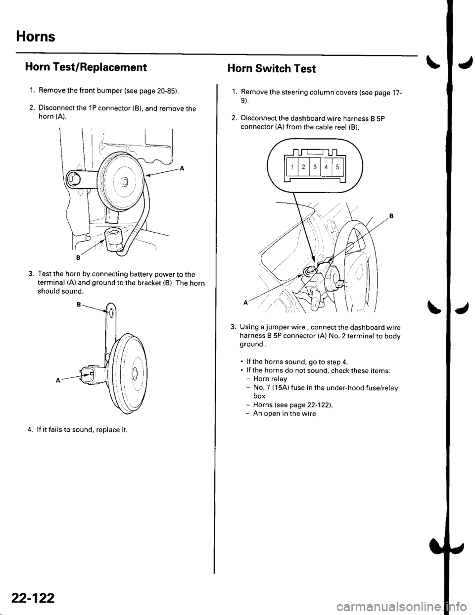
Remove the front bumper {see page 20-85).
Disconnect the 1P connector (B), and remove thehorn (A).
Test the horn by connecting battery power to the
terminal (A) and ground to the bracket (B). The horn
should sound.
4. lf it fails to sound, replace it.
22-122
1.
Horn Switch Test
Remove the steering column covers (see page '17-
9).
Disconnecl the dashboard wire harness B 5P
connector (A) from the cable reel (B).
Using a jumper wire . connect the dashboard wire
harness B 5P connector (A) No. 2 terminal to bodyground .
. lf the horns sound, goto step 4.. lf the horns do notsound, checkthese items:- Horn relay- No.7 (15A)fuse in the under-hood fuse/relay
box- Horns (see page 22-122).- An open in the wire
| ../......:....,
Page 975 of 1139
Wipers/Washers
Washer Motor Test
1. Partially remove the right inner fender (see page
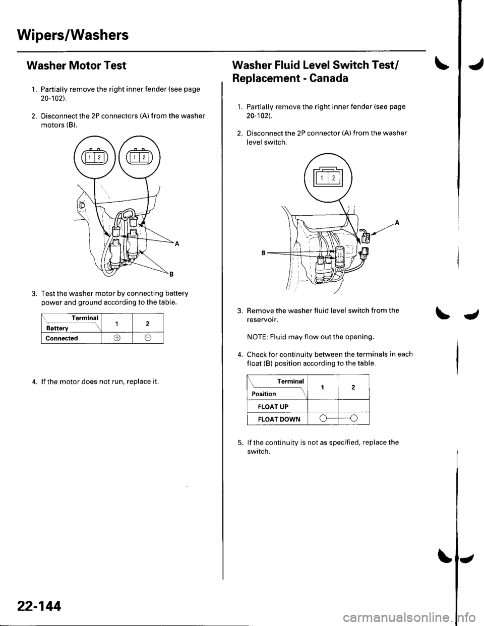
20-'t021.
2. Disconnect the 2P connectors (A) from the washer
motors (B).
Test the washer motor by connecting battery
power and ground according to the lable.
Terminal
Battery12
Connected@o
4. lf the motor does not run, replace it,
22-144
Washer Fluid Level Switch Test/
Replacement - Canada
1.
3.
4.
Partially remove the right inner fender (see page
20-102).
Disconnect the 2P connector {A) from the washer
level switch.
Remove the washer fluid level switch from the
reservoir.
NOTE: Fluid may flow out the opening.
Check for continuity between the terminals in each
float (B) position according to the table.
Terminal
Position2
FLOAT UP
FLOAT DOWNo----o
lf the continuity is not as specified. replace the
swtTcn.
Page 980 of 1139
Accessory Power Socket
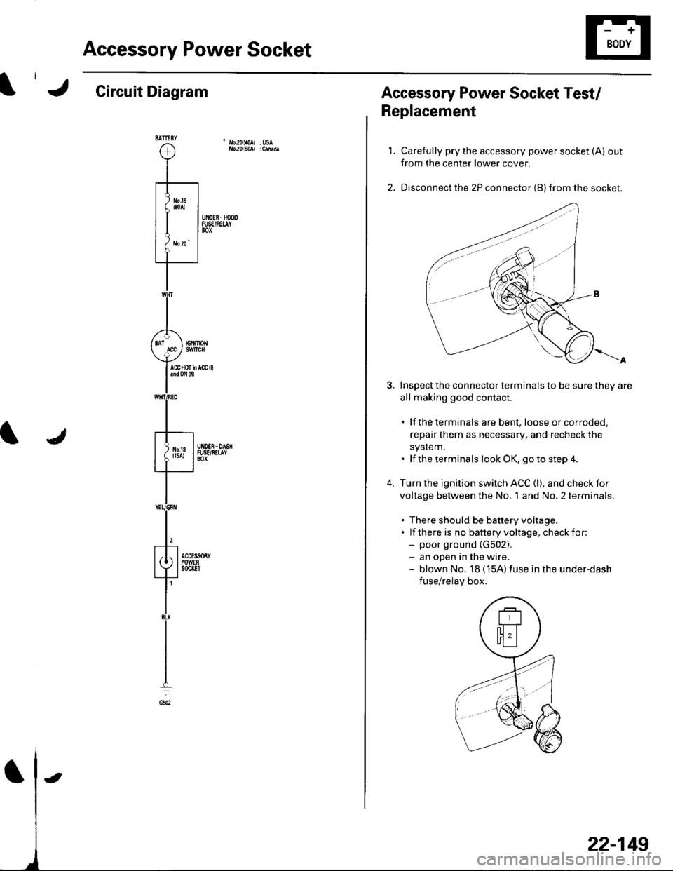
Circuit Diagram
22-149
Accessory Power Socket Test/
Replacement
1.
4.
Carefully pry the accessory power socket (A) out
from the center lower cover.
Disconnect the 2P connector (B) from the socket.
Inspect the connector terminals to be sure they are
all making good contact.
. lf the terminals are bent, loose orcorroded,
repairthem as necessary, and recheck the
system.. lf the terminals look OK, go to step 4.
Turn the ignition switch ACC (l), and check for
voltage between the No. 'l and No. 2 terminals.
. There should be battery voltage.. lf there is no banery voltage, checkfor:- poor ground {G502).- an open in the wire.- blown No. 18 (15A)fuse in the under-dash
fuse/relay box.
Page 1012 of 1139
Seat Belts
Front Seat Belt Replacement
SRS comDonents are located in this area. Review the
SRS component locations (see page 23-13) and the
precautions and procedures (see page 23-14) in the SRS
section before performing repairs or service,
NOTE: Check the front seat belts for damage, and
replace them if necessary. Be careful not to damage
them during removal and installation.
Front Seat Belt
Make sure you have the anti-theft code for the radio,
then write down the frequencies for the preset
buttons.
Disconnect the negative cable from the battery, and
wait at least 3 minutes before beginning work.
Slide the front seat forward fully.
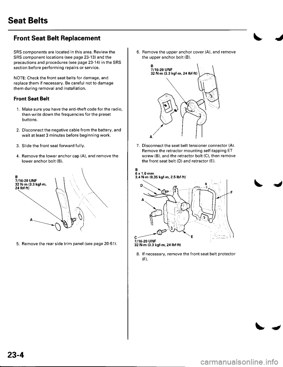
Remove the lower anchor cap (A), and remove the
lower anchor bolt (B).
3.
1.
5. Remove the rear side trim panel (seepage20-51).
23-4
qt
B7/16-20 UNF32 N m (3.3 kgf.m,24lbt.ft)
7. Disconnect the seat belt tensioner connector (A).
Remove the retractor mounting self-tapping ET
screw {B), and the retractor bolt (C), then remove
the front seat belt (D) and retractor (E).
6x1.0mm3.4 N m {0.35 kgf.m,2.5 lbf.ft)
6. Remove the upper anchor cover {A), and remove
the upper anchor bolt (B).
7/16-20 UNF32 N.m (3.3 kgf m,2ir lbf.ft)
8. lf necessary, remove the
(F).
front seat belt protecto
Page 1014 of 1139
Seat Belts
Front Seat Belt Replacement (cont'd)
Seat Belt Buckle
1. Make sure you have the anti-theft code for the radio,
then write down the frequencies for the preset
buttons.
2. Disconnect the negative cable from the battery ,and wait at least 3 minutes before beginning work.
3. Remove the front seat (see page 20-7'1).
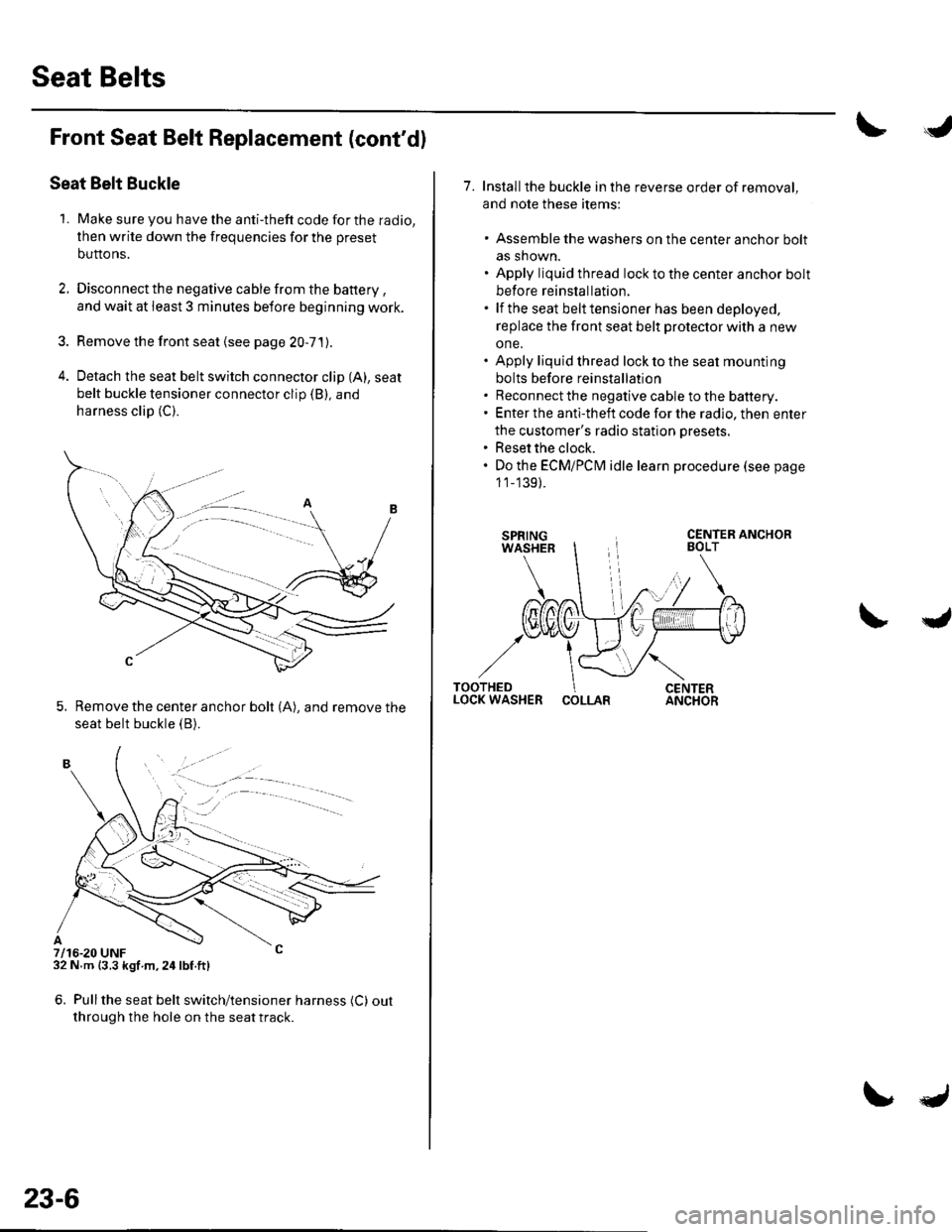
4. Detach the seat belt switch connector clip (A), seat
belt buckle tensioner connector clip (B), and
harness clip (C).
5. Remove the center anchor bolt (A), and remove the
seat belt buckle {B).
7/16-20 UNF32 N m {3.3 kgf m,24lbf.ft)
6. Pullthe seat belt switch/tensioner harness (C) out
through the hole on the seat track.
. -.. :.a--
23-6
7. Installthe buckle in the reverse order of removal,
and note these items:
. Assemble the washers on the center anchor bolt
as shown.. Apply liquid thread lock to the center anchor bolt
before reinstallation.. lf the seat belt tensioner has been deployed,
replace the front seat belt protector with a new
one.. Apply liquid thread lock to the seat mounting
bolts before reinstallation. Reconnect the negative cable to the battery.. Enter the anti-theft code for the radio, then enter
the customer's radio station presets.. Reset the clock.. Do the ECMiPCM idle learn procedure (see page
1 1_139).
COLLAR
Page 1021 of 1139
sRs
Precautions and Procedures
General Precautions
Please read the following precautions carefully beforeperforming airbag system service. Observe theinstructions described in this manual. or the airbags
could accidentally deploy and cause damage or injuries.
. Except when performing electrical inspections.
always turn the ignition switch OFF, disconnect the
negative cable from the battery, and wait at least 3minutes before beginning work.
NOTE: The memory is not erased even if the ignition
switch is turned OFF or the battery cables are
disconnected from the battery.. Use replacement pans which are manufactured to the
same standards and quality as the original parts. Do
not install used SRS parts from another vehicle. Useonly new pans when making SRS repairs.. Carefully inspect any SRS part before you install it.
Do not install any part that shows signs of being
dropped or improperly handled, such as dents, cracks,
or deformation.
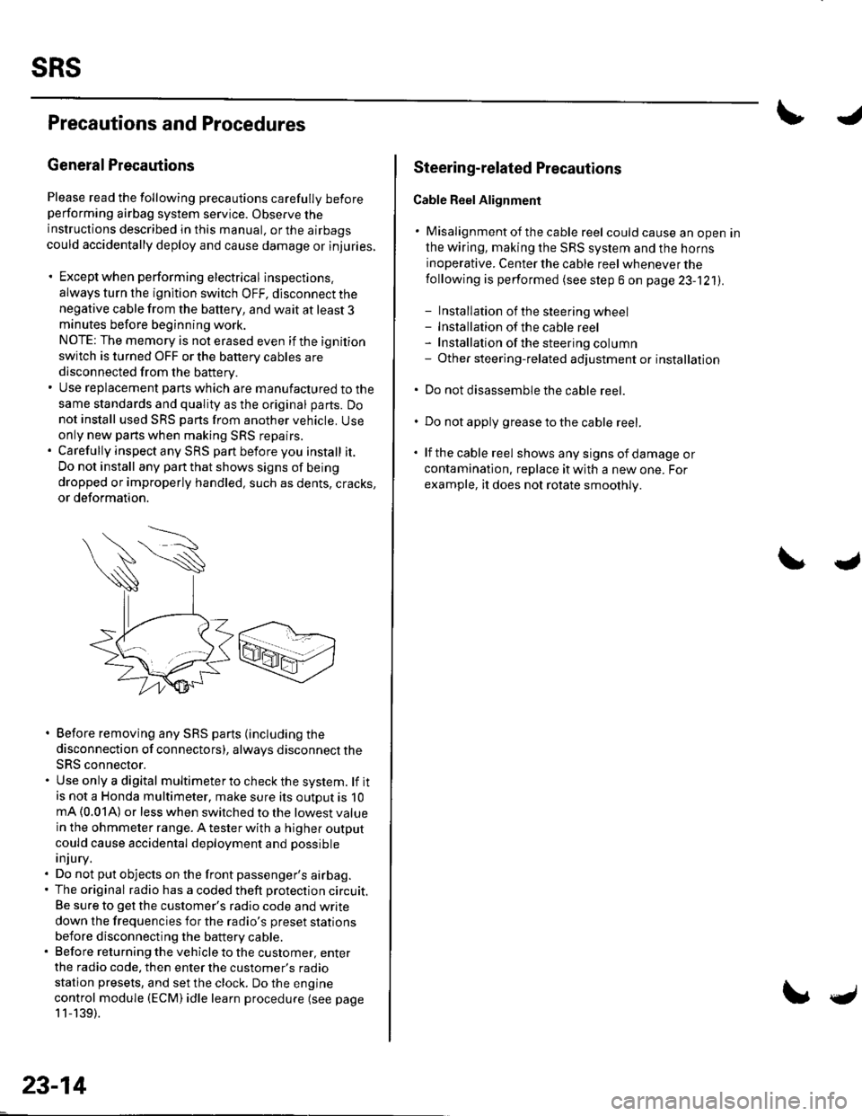
. Before removing any SRS parts (including the
disconnection of connectors), always disconnect the
SRS connector.. Use only a digital multimeter to check the system. lf itis not a Honda multimeter, make sure its outout is 10mA (0.01A) or less when switched to the lowest value
in the ohmmeter range. A tester with a higher output
could cause accidental deployment and possible
injury.. Do not put objects on the front passenger's airbag.. The original radio has a coded theft protection circuit.
Be sure to get the customer's radio code and write
down the frequencies for the radio's preset stations
before disconnecting the battery cable.. Before returning the vehicle to the customer, enter
the radio code. then enter the customer's radio
station presets, and set the clock. Do the engine
control module (ECM) idle learn procedure (see page
11-139).
23-14
c
Steering-related Plecautions
Cable Reel Alignment
. Misalignment of the cable reel could cause an open in
the wiring, making the SRS system and the horns
inoperative. Center the cable reel whenever the
following is performed (see step 6 on page 23-121).
- Installation of the steering wheel- Installation of the cable reel- Installation ofthe steering column- Other steering-related adjustment or installation
. Do not disassemble the cable reel.
. Do not apply grease to the cable reel.
. lf the cable reel shows any signs of damage or
contamination. replace it with a new one. For
example, it does not rotate smoothly.