lights HONDA CIVIC 2002 7.G User Guide
[x] Cancel search | Manufacturer: HONDA, Model Year: 2002, Model line: CIVIC, Model: HONDA CIVIC 2002 7.GPages: 1139, PDF Size: 28.19 MB
Page 337 of 1139
ldle Control System
DTC Troubleshooting
DTC P0505: ldle Control System Malfunction
NOTE: lf DTC P1519 is stored atthe same time as DTC
P0505, troubleshoot DTC P1519 first, then recheck for
DTC P0505.
1. Start the engine. Hold the engine at 3,000 rpm with
no load (in neutral) until the radiator fan comes on,
then let it idle,
2. Checkthe engine speed at idle with no,load
conditions: headlights, blower fan, rear defogger,
radiator fan, and air conditioner off.
Is the engine running at 750t50 rpm?
YES - Intermittent failure, system is OK at this
trme.I
NO lf the idle speed is less than 700 rpm, go to
step 3; if it's 800 rpm or higher, go to step 4.
3. Disconnect the idle air control {lAC) valve3P
connector.
Does the engine speed increase or fluctuate?
YES- Check the idle speed {see page 1 1-138). lf the
idle will not adjust properly, clean the passage in
the throttle body, and then adjust the idle. I
NO- Replace the IAC valve.I
4. Turn the ignition switch OFF.
5. Remove the intake air duct from the throttle body.
6. Start the engine, and let it idle.
11-130
(
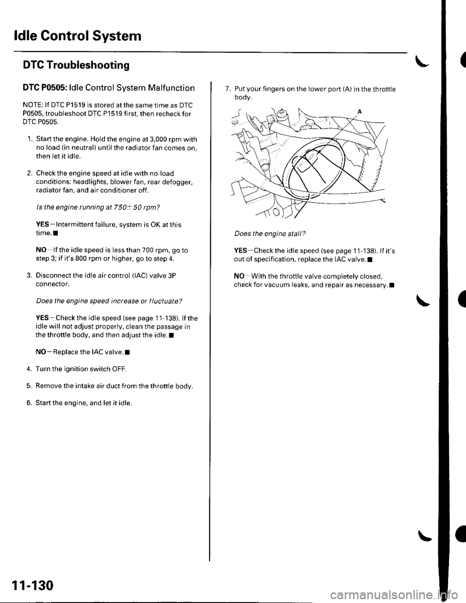
7. Put your fingers on the lower pon (A) inthethrottle
oooy.
Does the engine stall?
YES Checkthe idle speed (see page 11-138). lfit's
out of specification, replace the IAC valve.l
NO With the throttle valve completely closed,
check for vacuum leaks, and repair as necessary.l
Page 341 of 1139
ldle Gontrol System
't.
Alternator FR Signal Circuit Troubleshooting
Disconnect the alternator 4P connector from the
alternalor.
Turn the ignition switch ON {ll).
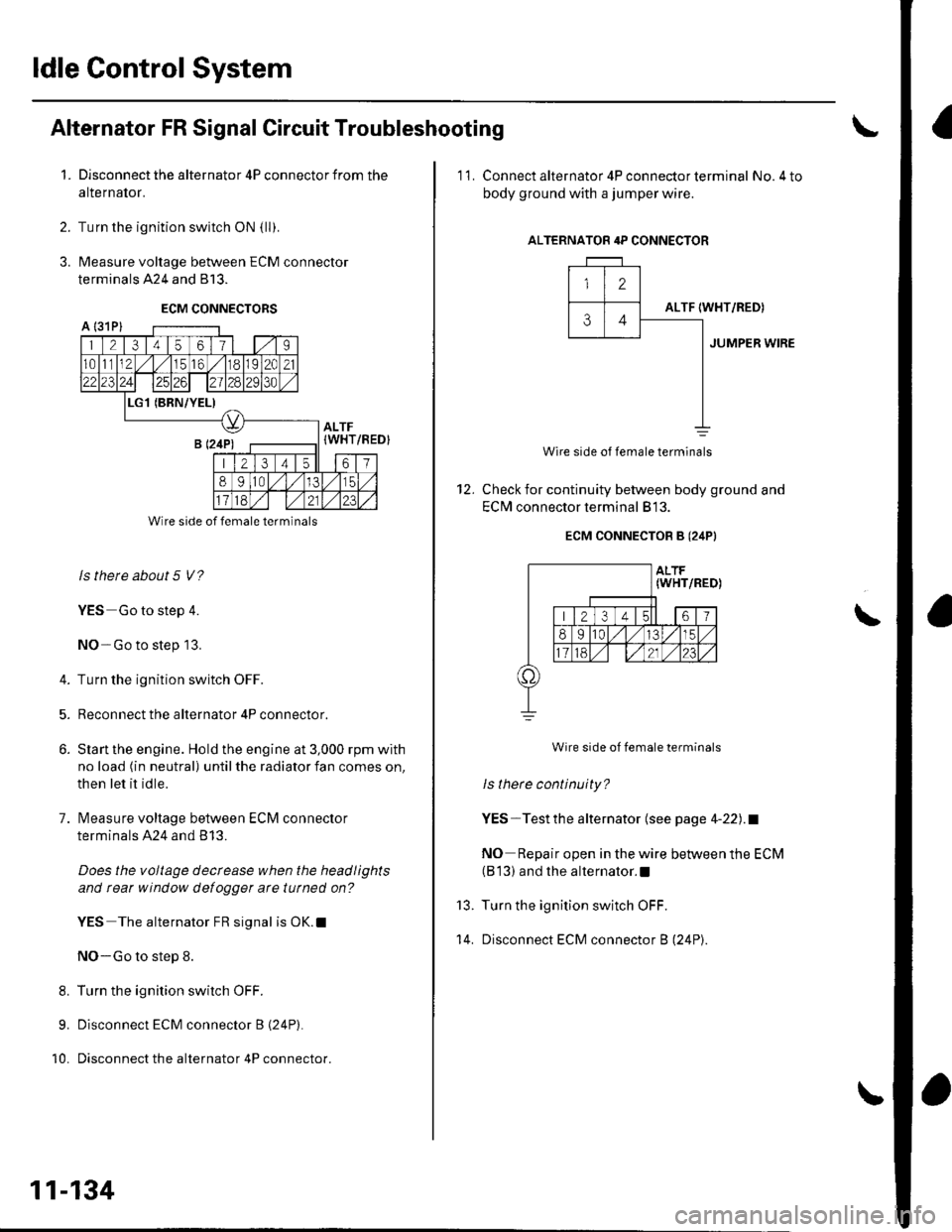
Measure voltage between ECM connector
terminals 424 and 813.
ECM CONNECTORS
2.
3.
A l31Pl
1 21345611 | 1.,'I
1011112,/56,/r8119l2C21
2312428129130
L(BRN/YEL)
ALTF(WHT
213 4t561
89ltal,/l/15
Wire side of female terminals
ls there about 5 V?
YES Go to step 4.
NO-Go to step 13.
4. Turn the ignition switch OFF.
5. Reconnect the alternator 4P connector.
6. Slan the engine. Hold the engine at 3,000 rpm with
no load (in neutral) until the radiator fan comes on,
then let it idle.
7. lvleasure voltage between ECM connector
terminals A24 and B 13.
Does the voltage decrease when the headlights
and rear window defogger arc tutned on?
YES The alternator FR signal is OK.l
NO-Go to step 8.
8. Turn the ignition switch OFF.
9. Disconnect ECM connector B (24P).
10. Disconnect the alternator 4P connector.
/REDI
11-134
'11. Connect alternator 4P con necto r term inal No.4 to
body ground with a jumper wire.
ALTERNATOR 4P CONNECTOR
12
ALTF34IWHT/RED)
JUMPER WIRE
12.
Wire side of female terminals
Check for continuity between body ground and
EClvl connector terminal 813.
ECM CONNECTOB B (24PI
Wire side of female terminals
ls there continuity?
YES-Testthe alternator (see page 4-22).1
NO Repair open in the wire between the ECM(B 13) and the alternator.l
Turn the ignition switch OFF.
Disconnect ECM connector B (24P).
\
13.
't 4.
Page 344 of 1139
Brake Pedal Position Switch Signal Circuit Troubleshooting
1. Check the brake lights.
Are the brake lights on without pressing the brakepedal?
YES Inspectthe brake pedal position switch(see page 19-6).I
NO Go to step 2.
2. Press the brake pedal.
Do the brake lights come on?
YES-Go to step 3.
NO Go to step 4.
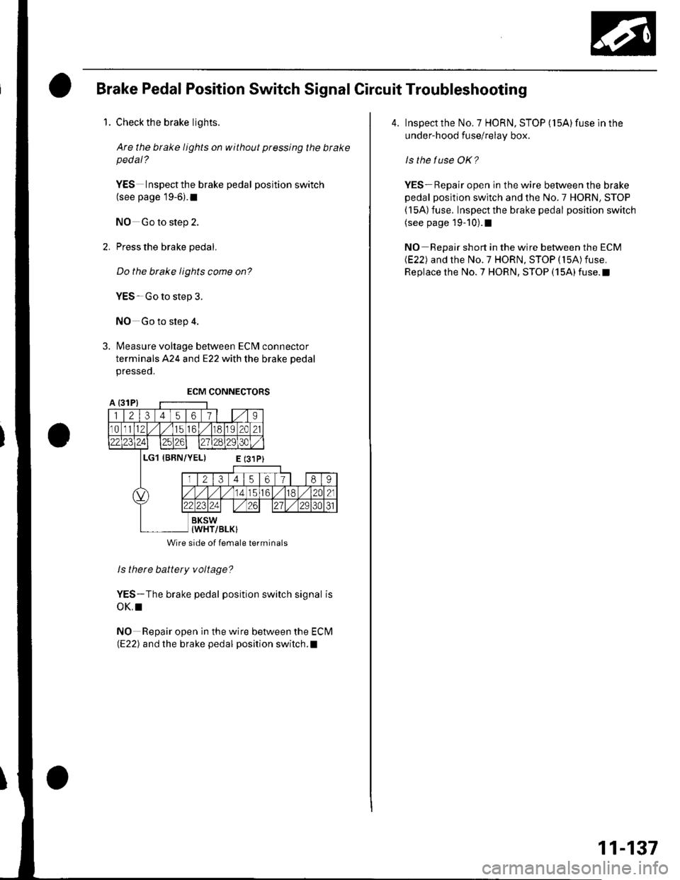
3. Measure voltage between ECM connector
terminals A24 and E22 with the brake pedal
presseo.
ls there battery voltage?
YES-The brake pedal position switch signal is
oK,I
NO Repair open in the wire between the Eclvl(E22) and the brake pedal position switch.l
Wire side of lemale terminals
4. Inspect the No. 7 HORN, STOP (15A) fuse ln the
under-hood fuse/relay box.
ls the tuse OK?
YES- Repair open in the wire between the brake
pedal position switch and the No.7 HORN, STOP( l5A) fuse, Inspect the brake pedal position switch(see page 19-10).1
NO Repair short in the wire between the ECM(E22) and the No.7 HORN, STOP (15A)fuse.
Replace the No.7 HORN, STOP (15A)fuse.t
11-137
Page 345 of 1139
ldle Control System
ldle Speed lnspection
NOTE:' Leave the idle air control (lAC) valve connecled.. Before checking the idle speed, check these items:- The malfunction indicator lamp (MlL) has not been
reported on.- lgnition timing- Spark plugs- Air cleaner- PCV system. Pullthe parking brake lever up. Start the engine, and
make sure the headlights are off.
1. Disconnect the evaporative emission (EVAP)
canister purge valve 2P connector.
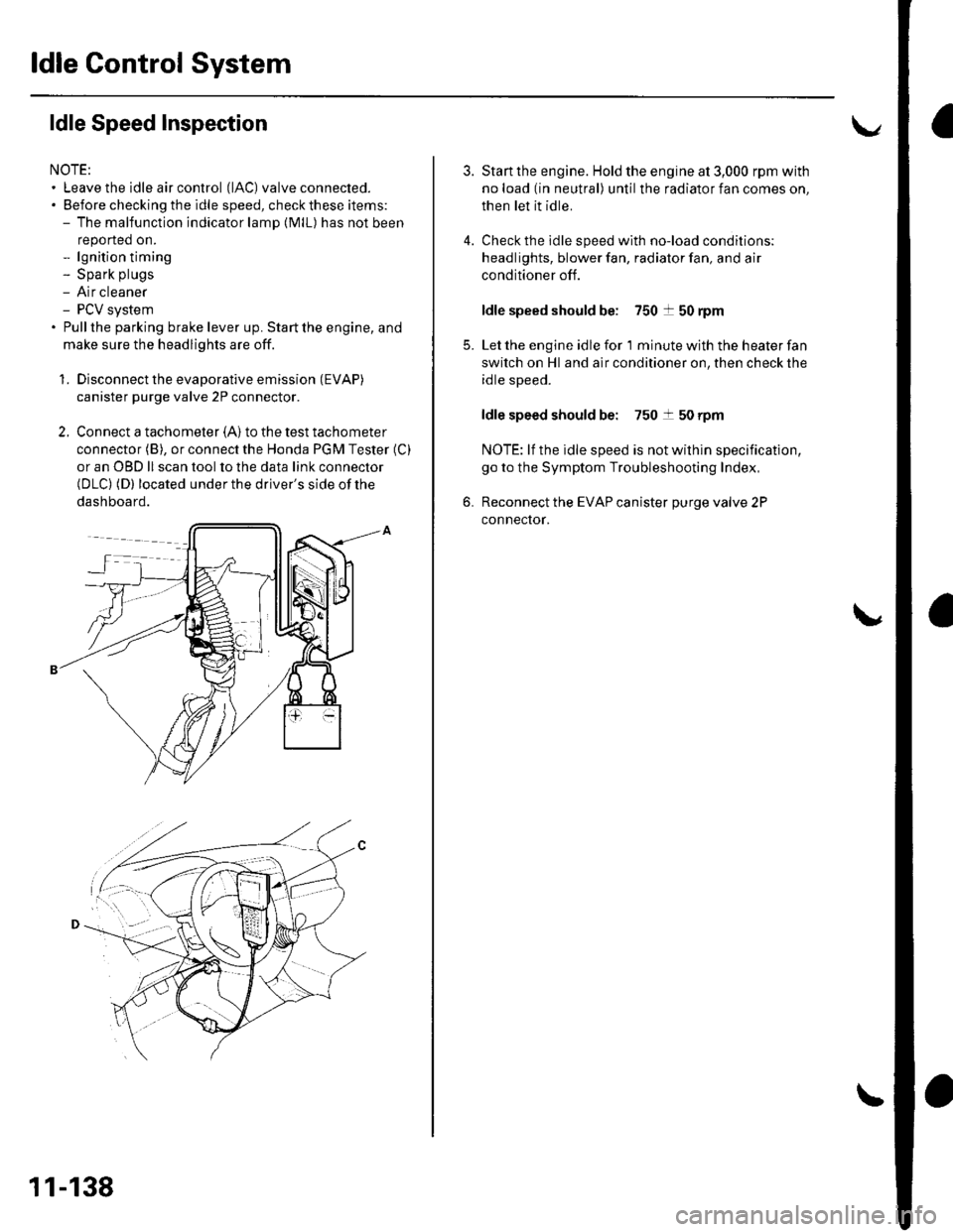
2. Connect a tachometer (A)to the test tachometer
connector (B), or connect the Honda PGM Tester (C)
or an OBD ll scan tool to the data link connector(DLC) (D) located under the driver's side of the
dashboard.
11-138
4.
3.
5.
6.
Start the engine. Hold the engine at 3,000 rpm with
no load (in neutral) until the radiator fan comes on,
then let it idle.
Check the idle speed with no-load conditions;
headlights, blower fan, radiator fan, and air
conditioner off.
ldle speed should be: 750 t 50 rpm
Let the engine idle for 1 minute with the heater fan
switch on Hl and air conditioner on, then check the
idle speed.
ldle speed should be: 750 t 50 rpm
NOTE: lf the idle speed is not wilhin specification,
go to the Symptom Troubleshooting Index,
Reconnect the EVAP canister purge valve 2P
connector.
Page 601 of 1139
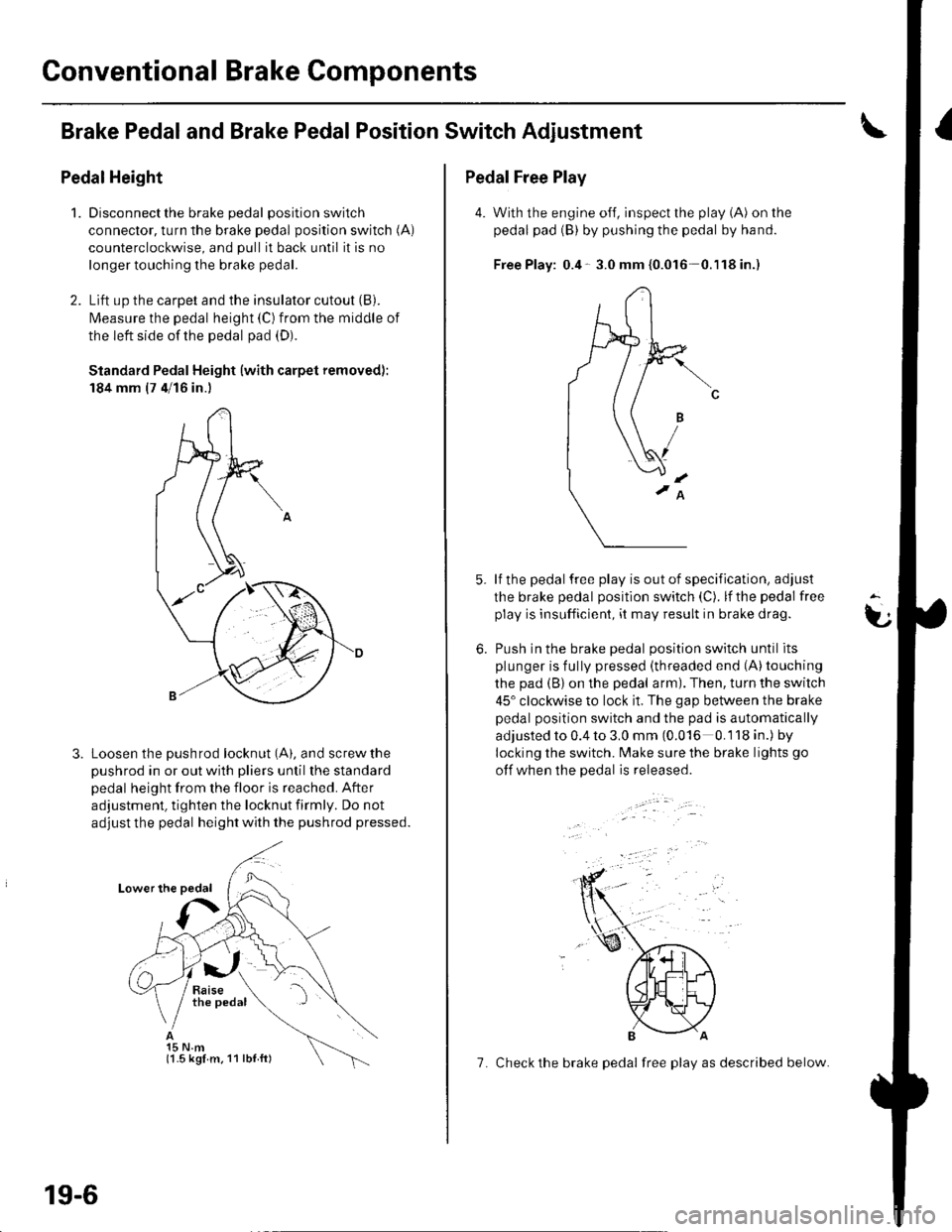
Conventional Brake Components
Brake Pedaland Brake PedalPosition Switch Adjustment
Pedal Height
1.Disconnect the brake pedal position switch
connector, turn the brake pedal position switch (A)
counterclockwise, and pull it back until it is no
longer touching the brake pedal.
Lift up the carpet and the insulator cutout (B).
l\4easure the pedal height (C) from the middle of
the left side of the pedal pad (D).
Standard Pedal Height (with carpet removed):
184 mm (7 4/16 in.)
Loosen the pushrod locknut (A), and screw the
pushrod in or out with pliers until the standard
pedal height from the floor is reached. After
adjustment, tighten the locknut firmly. Do not
adjust the pedal height with the pushrod pressed.
15 N.m(1.5 kgl m. 11 lbl ft)
19-6
7. Check the brake pedal free play as described below.
Pedal Free Play
4. With the engine off, inspect the play (A) on the
pedal pad (B) by pushing the pedal by hand.
Free Play: 0.4- 3.0 mm {0.016 0.'l18in.)
lf the pedal free play is out of specification, adjust
the brake pedal position switch (C). lf the pedal free
play is insufficient, it may result in brake drag.
Push in the brake oedal oosition switch until its
plunger is fully pressed (threaded end (A)touching
the pad (B) on the pedal arm). Then, turn the switch
45" clockwise to lock it. The gap between the brake
pedal position switch and the pad is automatically
adjusted to 0.4 to 3.0 mm (0.016 0.118 in.) by
locking the switch. Make sure the brake lights go
otf when the pedal is released.
t
6.
Page 708 of 1139
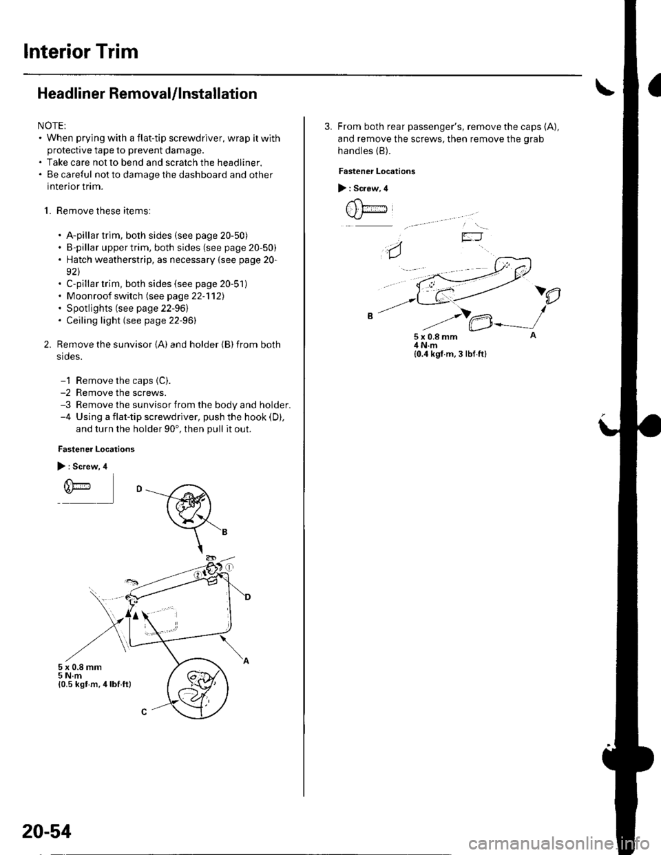
Interior Trim
Headliner RemovaUlnstallation
NOTE:. When prying with a flat-tip screwdriver, wrap itwith
protective tape to prevent damage.. Take care not to bend and scratch the headliner.. Be careful not to damage the dashboard and other
interior trim.
1. Remove these items:
. A-pillar trim, both sides (see page 20-50). B-pillar uppertrim, both sides (see page 20-50). Hatch weatherstrip, as necessary {see page 20-
92\. C-pillar trim, both sides (see page 20-51). Moonroof switch (see page 22-'112). Spotlights (see page 22-961. Ceiling light (see page 22-96)
Remove the sunvisor {A) and holder {B) from both
srdes.
-1 Remove the caps {C).-2 Remove the screws.-3 Remove the sunvisor from the body and holder.-4 Using a flat-tip screwdriver, push the hook (D),
and turn the holder 90'. then pull it out.
Fastener Locations
> : Screw, 4
r(\'-r)*
5x0.8mm5 N.m{0.5 kst m.4lbf ft}
20-54
3. From both rear passenger's, remove the caps (A),
and remove the screws, then remove the grab
handles (B).
Fastener Locations
> : Screw, 4
t , t;---iJ
)e
5x0.8mm4 N.m{0.4 kgf.m, 3 lbf.ft}
Page 783 of 1139
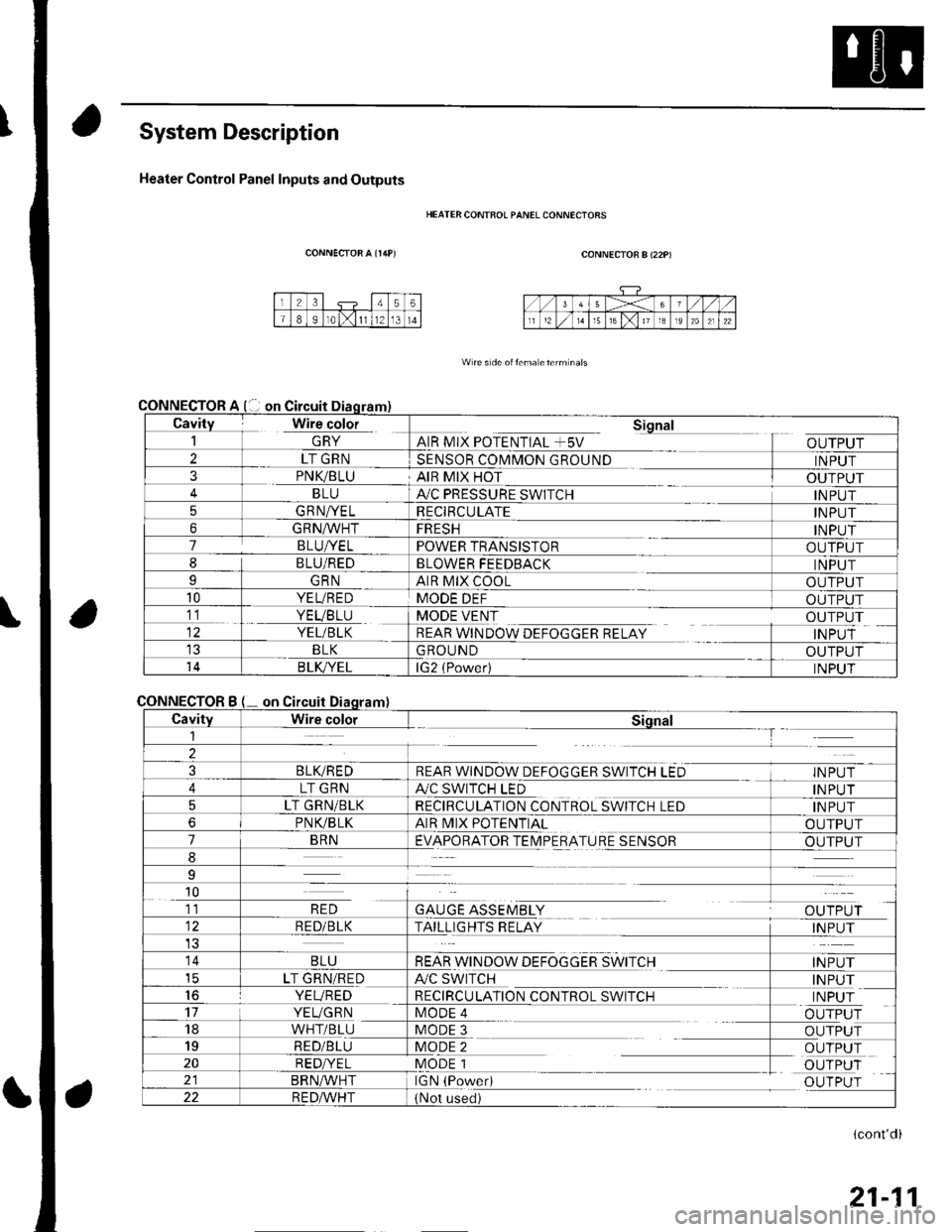
System Description
Heater Control Panel Inputs and Outputs
CONNECTOR A {r/rP)
CONNECTOR
CONNECTOR
HEATER CONTFOL PANEL CONNECIORS
CONNECTOR B (22P)
W re s de oitema eterm nals
Cavity Wire color_| \ln YAIR MIX POTENTIAL +5V
Sional
OUTPUT2LT GRNSENSOR COMMON GROUNDINPUT3PNK/BLUAIR MIX HOTOUTPUTBLUA,/C PRESSURE SWITCHINPUT5GRNA/ELRECIRCULATEINPUT6GRNA/VHTFRESHINPUT7BLUI/ELPOWER TRANSISTOROUTPUT8BLU/REDBLOWER FEEDBACKINPUTIGRNAIR MIX COOLOUTPUT10YEL/REDMODE DEFOUTPUT11. YEVBTU
YEL/BLK
MODE VENT
REAR WINDOW DEFOGGER RELAY
OUTPUT
INPUTBLKGROUNDOUTPUT14B LK/YELlG2 (Power)INPUT
Bon
CavityWire colorSiqnal1--T
2
3BLIVREDREAR WINDOW DEFOGGER SWITCH LEDINPUT
4LT GRNA./C SWITCH LEDINPUT
5LT GRN/BLKRECIRCULATION CONTROL SWITCH LEDINPUT
6PNVBLKAIR MIX POTENTIALOUTPUT
7BRNEVAPORATOR TEIMPERATURE SENSOROUTPUT
8
9
10
GAUGE ASSEMBLYal' 'TDr ri11RED
RED/BLKTAILLIGHTS RELAYINPUT
14BLUREAR WINDOW DEFOGGER SWITCHINPUTicLT GRN/REDA/C SWITCHINPUT16YEVREDRECIRCULATION CONTROL SWITCHINPUT17YEUGRNMODE 4OUTPUT18WHT/BLUMODE 3OUTPUT19RED/BLUMODE 2OUTPUT20RED/YELMODE 1OUTPUTBRN^,^/HTIGN (PowedOUTPUT22R E DA/r'HT(Not used)
(cont'd)
21-11
Page 831 of 1139
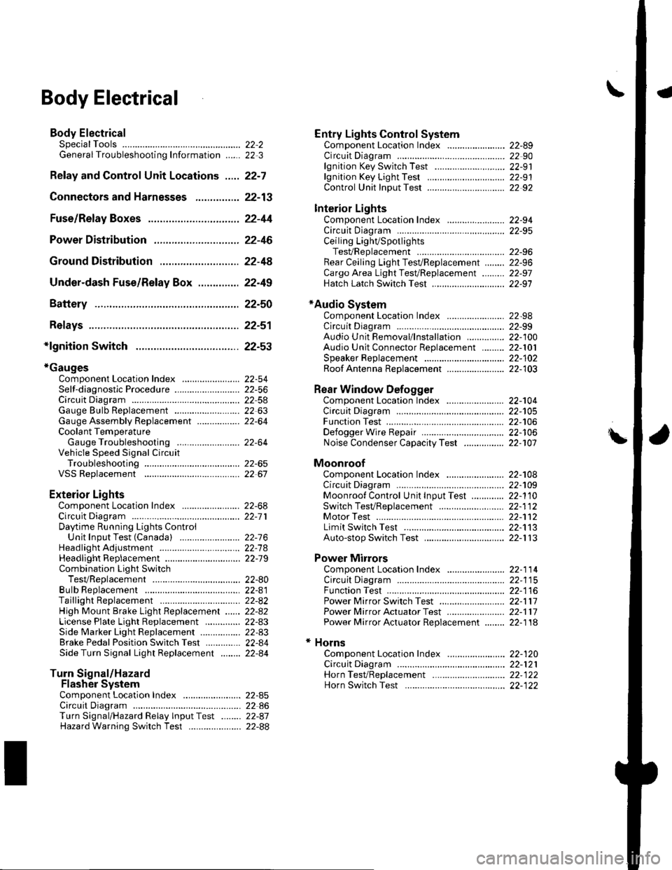
\Body Electrical
Body ElectricalSpecialToolsGeneral Troubleshooting tntorrnaiion.'......
Relay and Control Unit Locations .....
Connectors and Harnesses
Fuse/Relay Boxes ...............................
Power Distribution .............................
Ground Distribution ...........................
Under-dash Fuse/Relay Box ..............
Battery ..............
Relays ................
*lgnition Switch ..............
*Gauges
Component Location Index .......................Self-diagnostic Procedure ..........................Circuit DiagramGauge Bulb Replacement ..........................Gauge Assembly ReplacementCoolant Temperature
Gauge Troubleshooting .... ....................Vehicle Speed Signal CircuitTroubleshootingVSS Replacement
Exterior LightsComponent Location Index .......................Circuit DiagramDaytime Running Lights ControiUnit Input Test (Canada) ........................Headlight Ad,ustment .................. .. .....Headlighr Replacement ..............................Combination Light SwitchTest/ReplacementBulb ReplacementTaillight Replacement ..........................High Mount Brake Light Replacement ......License Plate Light Replacement ..............Side Marker Light Replacement ................Brake Pedal Position Switch Test ..............Side Turn Signal Light Replacement ........
Turn Signal/HazardFlasher SystemComponent Location Index .......................Circuit DiagramTurn Signal/Hazard Relay lnputTest ........Hazard Warning Switch Test
22,3
22-7
22-13
22-44
22-46
22-4A
22-49
22-50
22-51
22-53
22-5422-5622-5422 6322-64
22-64
22-6522 61
22-6822--71
22-7 622-7422-79
22-AO22-4122-8222-4222-4322-4322-4422-84
22-8�522 A622-8722-88
22-10422-105
22-10622-107
Entry Lights control systemComponent Location Index ....................... 22-89Circuit Diagram ......... 22 90lgnition Key Switch Test .....................,...... 22-9'llgnition Key Light Test ............................... 22-91Control Unit Input Test ..........,.................... 22 92
Interior LightsComponent Location Index ....................... 22-94Circuit Diagram ......... 22-95Ceiling LighVSpotlightsTesVReplacement ................................... 22-96Rear Ceiling Light TesVReplacem ent ........ 22-96Cargo Area Light Test/Replacem ent ......... 22-97Hatch Latch Switch Test ..,..,....................... 22-97
*Audio SystemComponent Location Index ....................... 22-98Circuit Diagram ......... 22,99Audio Unit Removal/lnstallation ............... 22-1OOAudio Unit Connector Replacement ......... 22-101Speaker Replacement ................................ 22-102Roof Antenna Rep1acement ....................-.. 22-103
Rear Window DefoggerComponent Location Index ...........Circuit Diasram .. ....... .. ..... ....... ...:::::.::.::.Function TestDefogger Wire Repair .................................Noise Condenser CapacityTest ................
MoonroofComponent Location Index ....................... 22-1OBCircuit Diagram ......... 22-109Moonroof Control Unit Input Test ............. 22-'l10Switch TesVReplacement ........,.....,........... 22-1 12Motor Test ................. 22-112Limit Swilch Test ...... 22-'l'13Auto-stop Switch Test ................................ 22-1 13
Power MirrorsComponent Location Index ....................... 22-114Circuit Diagram ......... 22-115Function Test ............. 22-116Power Mirror Switch Test .......................... 22-ll7Power Mirror Actuator Test ....................... 22-117Power Mirror Actuator Replacement ........ 22-11A
* HornsComponent Location Index ....................... 22-120Circuit Diagram ......... 22-121Horn TesVReplacement ...........................-. 22-122Horn Switch Test .,.... 22-122
\
Page 839 of 1139
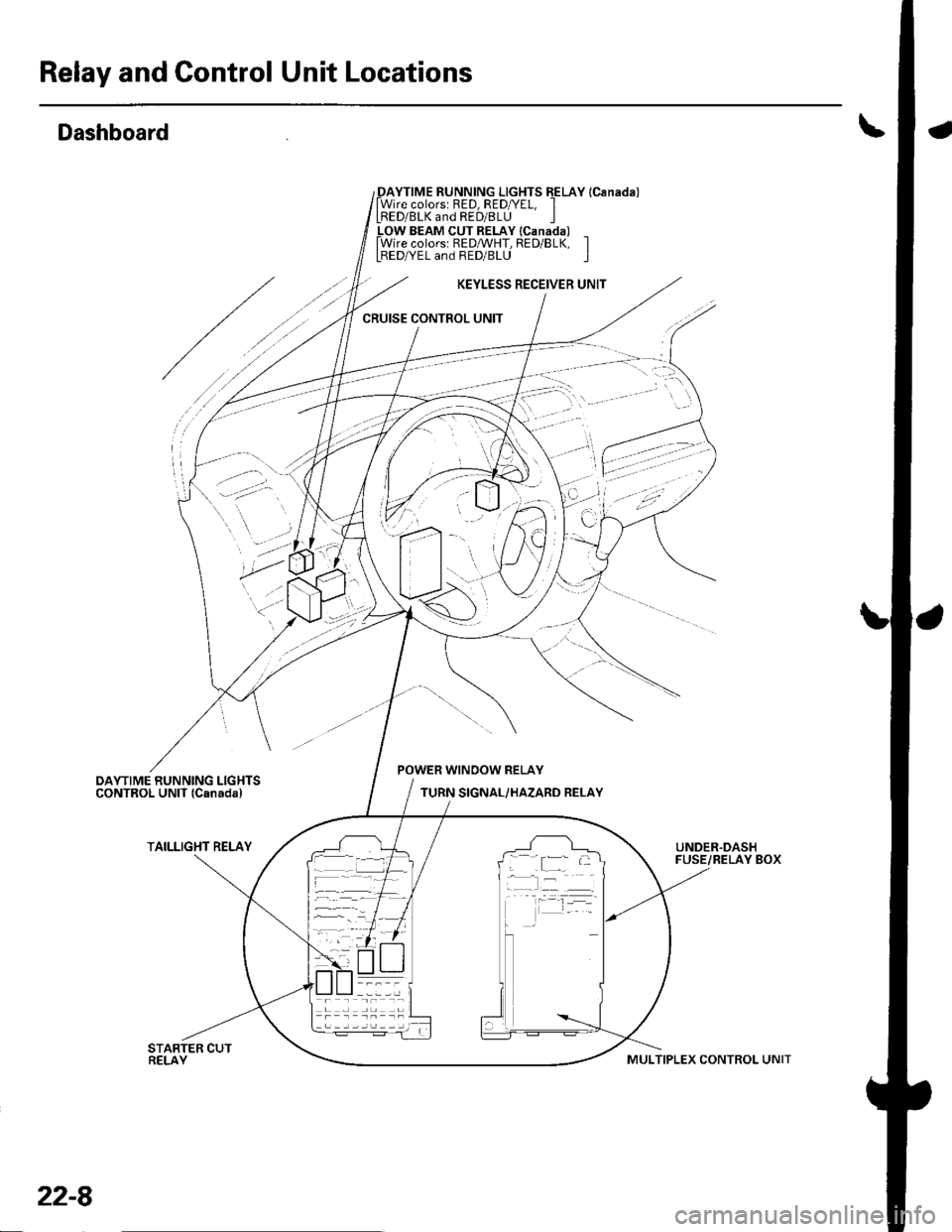
Relay and Gontrol Unit Locations
Dashboard
_DAYTIME RUNNING LIGHTS EELAY lCanada)lWire colorsr RED, RED/YEL, ILRED/BLK and RED/8LU I_LOW BEAM CUT RELAY lcanada) _lWire colors: REDMHT, RED/BLK, ILBEDA/EL and RED/BLU I
KEYLESS RECEIVER UNIT
CRUISE CONTROL UNIT
'
'-.:- ':
..? ;,
POWER WINOOW RELAY
TURN SIGNAL/HAZARD RELAY
TAILLIGHT RELAYUNDER.DASHFUSE/RELAY BOX; .[:_- -
-l:r --
22-8
MULTIPLEX CONTROL UNIT
Page 844 of 1139
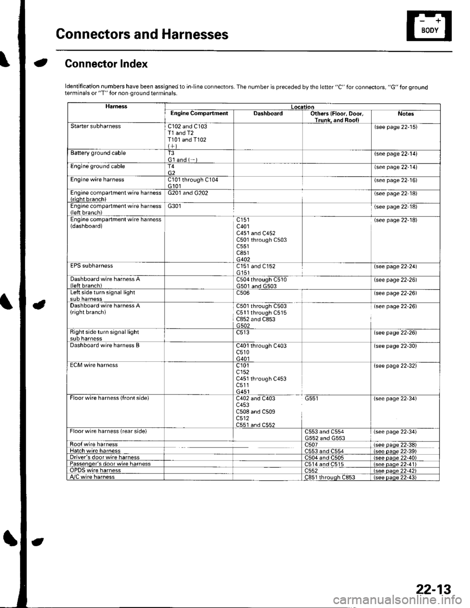
Gonnectors and Harnesses
aGonnector Index
ldentification numbers have been assigned to in-line connectors. The number is preceded by the letter "C" for connectors, "G" for groundterminals or "T" for non ground terminals.
HamessLocationEngine CompartmentDashboardOthers {Floor, Door,Trunk. and Roo{lNot€s
Starter subharnessC102 and C103T1 and T2T101 and T102
(see page 22-15)
Battery ground cableT3G'l and ( -{see page 22-l!)
Engine ground cableT4{see page 22-14)
Engine wire harnessCl0l through C104G 101(see page 22 16)
Engine compartment wire harness{rioht branchiG201 and G202(see page 22 18)
Engine compartment wire harness(left brench)G301(see page 22 18)
Engine compartment wire harness(dashboard)c401C451 and C452C501 through C503c551c851G402
(see page 22-18)
EPS subharnessC151 and C152G'151\see page 22 241
Dashboard wire harness Alleft branch)C504 through C510G501 and G503(see page 22-26)
Left side turn signal lightc506(see page 22-26)
Dashboard wire harness A(right branch)C50l through C503C5ll through C515C852 and C853G502
(see page 22-26)
Right side turn si9nal lightsub harnesslsee page 22-26)
Dashboard wire harness BC40l through C403c510G40l
(see page 22-30)
ECM wire harnessc101cl52C451 through C453c511G451
{see page 22-32}
Floorwire harness (front side)C402 and C403 G551c453C508 and C509c512C551 an.l C55?
(see page 22'34)
Floor wire harness (rear side)C553 and C554(see page 22-34)
Roo{ wire harnessc507(see paqe 22-38)Hatch wire harnessC553 and C554(s6e paqe 22'39)Driver's door wire harnessC504 and C505(see paqe 22-40)Passenqer's door wi.e harness514 and C515(see oaoe 22-41Te harness)552(see oaqe 22-42i/C wire harnessc851 rhrouoh c853(see paqe 22.43i
22-13